Heat Control System
Randy Fatula
rlf94@cornell.edu
Introduction
This project was the first stage of developing a controller for a radiant floor heat system. The microcontroller will use inputs from thermostats, thermocouples, a flow meter, and pressure switches to control the operation of the pumps and valves to achieve improved efficiency of the system as a whole.
This project idea came from a friend who recently built a house which utilizes an outdoor wood boiler for heating. He expressed that he was disappointed in the efficiency of the current system and wished he had more control over the system operation. This seemed like a good application of what I’ve learned in this course. The main goal is to improve the efficiency of the system by shortening the amount of time that the Pumps need to run while still properly heating the home. By doing this, consumption of both electricity and wood will be reduced.
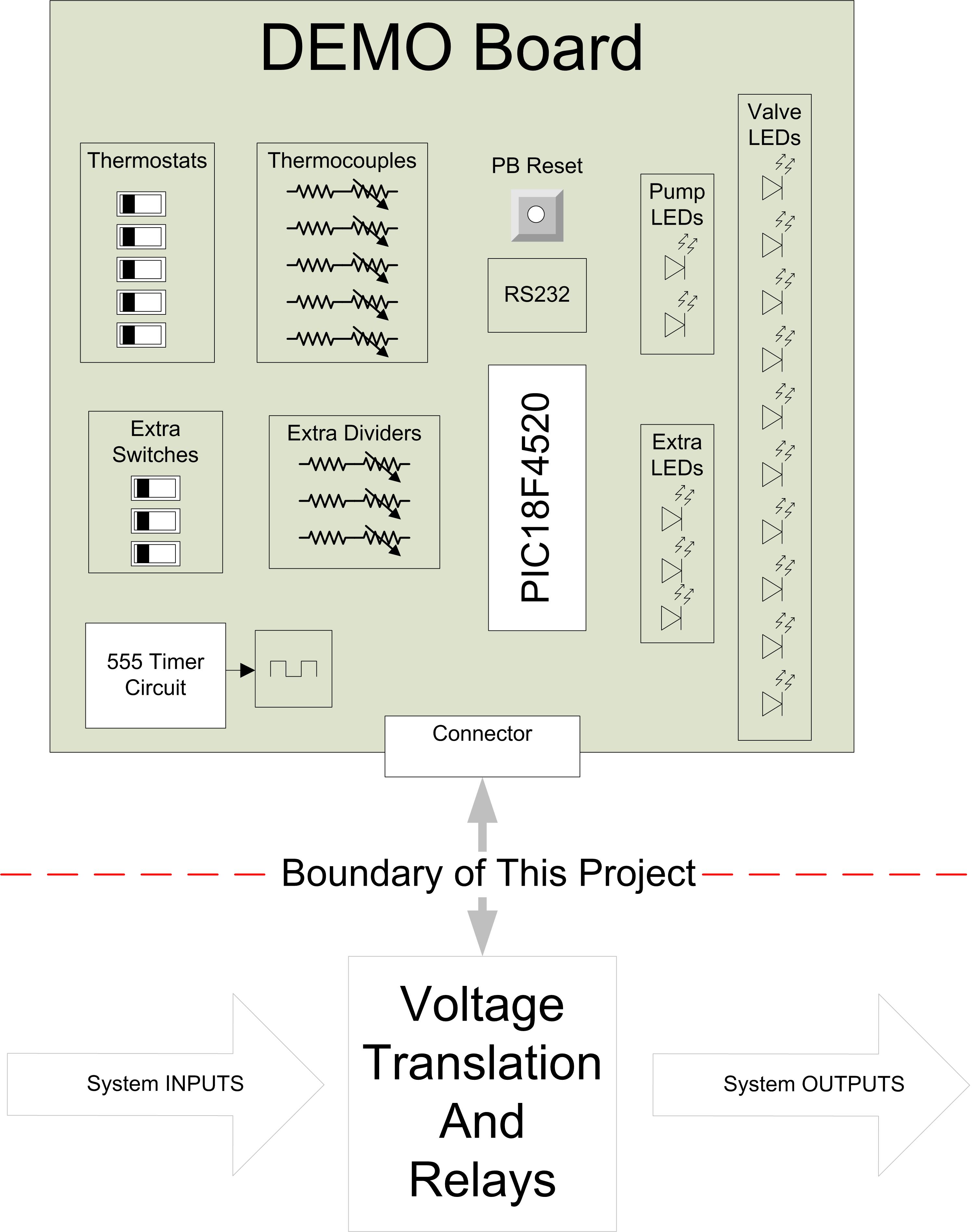
Implementation of this project involves a large amount of work outside of the microprocessor. Because of this, I bound the scope of this academic project to the control logic only. In order to implement this in the house, I will have to build the circuitry to translate the control logic over to the voltages necessary for operation of the valves, pumps and sensors. In order to verify and validate the controller logic worked as desired I built a demonstration board that models the inputs and outputs of the system. This board was used to debug the controls during development and it was also a convenient way of demonstrating this project at the end of the semester. Toggle switches were used to model the 5 thermostats, adjustable voltage dividers were used for thermocouples, a 555 Timer circuit was used for the flow meter and LEDs were used for all outputs.
Figure 1 - Project Boundary
High Level Design
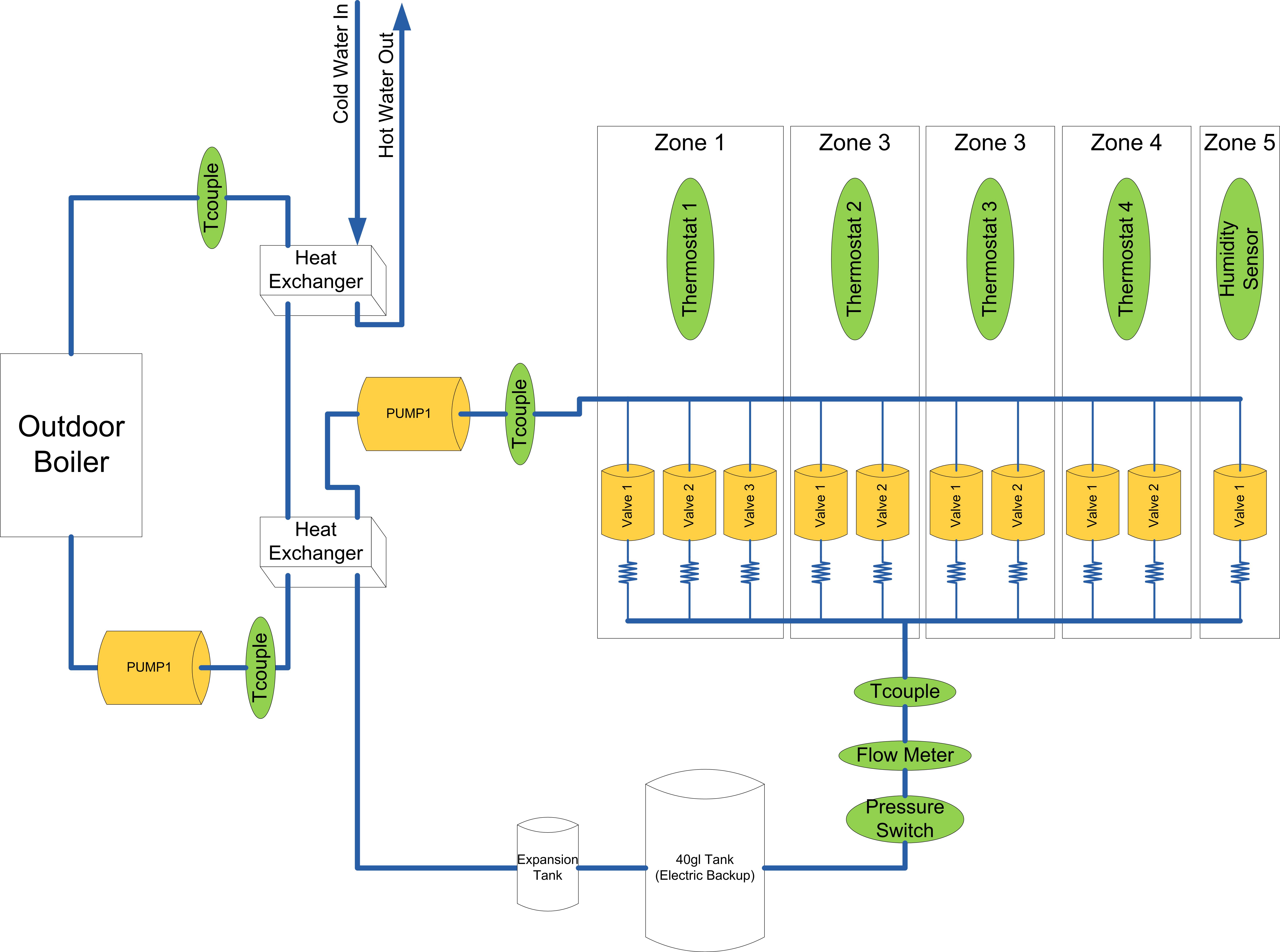
The primary goal of this project is to improve the efficiency of heating a home that utilizes radiant floor heating. Several improvements over the current system will achieve this goal. The five major upgrades are compared here with Figures 2 and 3 showing the system before and after:
1. Outside Pump will be controlled based on demand for Heat and Domestic Hot water
a. Old system – this pump was always on
2. Each Valve will be opened one at a time to maximize the flow rate to a single loop. This will decrease the time it will take to insert heat into the zone and hopefully reduce the amount of time the pumps need to run.
a. Old System – many valves could be opened at the same time. The more valves that were opened, the longer it would take to warm up any of the loops. Not all loops may warm up at the same rate.
3. The heat exchanger in the attic will be warmed up based on current temperature and if the air handler is running (to reduce/prevent condensation).
a. Old System –Heat was sent to attic constantly @ 20minutes ON, then 40 minutes OFF. This ran regardless of the temperature up there or if the air handler was operating.
4. A Pressure sensor and Flow meter will be added to detect if a leak or blockage has occurred. The system will be shut down if either of these conditions is detected.
a. Old System – there were NO such safety features.
5. The system will provide real time data to the homeowner including: Pump/Valve Events, Thermocouple measurements. This data can be analyzed to make adjustments to the system operation for further improvements on it’s operation.
a. Old System – There was no feedback of the system operation.
Figure 2 - Old System
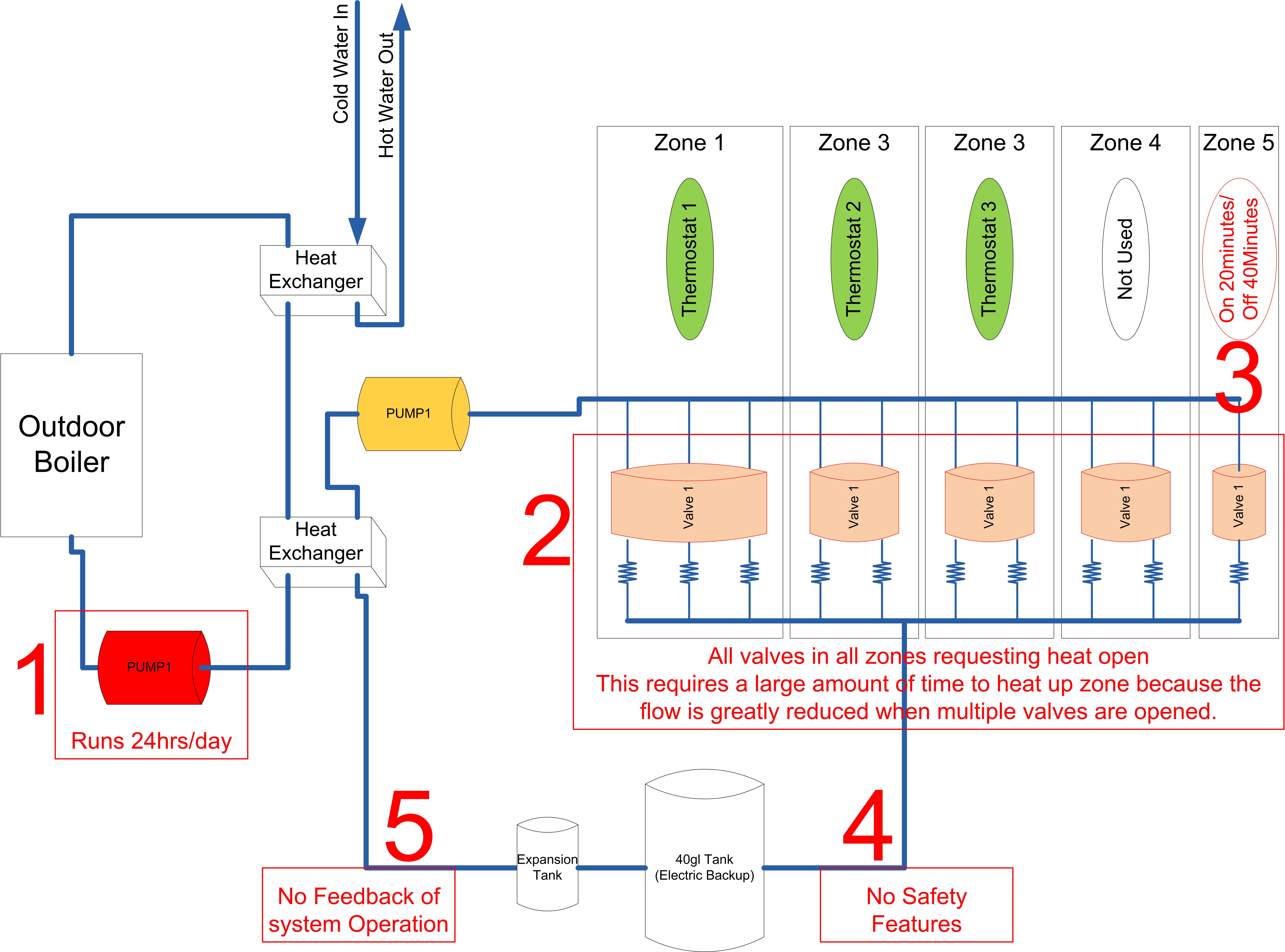
Figure 3 - Upgraded System
Equations
Thermocouples – The range of our ADC is 0-5v but our expected temp ranges are: 60-180degF for Hot sensors and 0-100 for the Attic sensor. Because of this we simply scaled/shifted the expected range into the ADC range. The following equations are the baseline we are starting with for development. Each of the thermocouples will be calibrated once in the real system.
![]()
![]()
BTU Calculation – At each pulse of the flow meter we will read the supply tcouple and return tcouple of the heat system, get a BTU calculation and then sum all the values of BTU. At the end of the cycle for that valve send out the summation of BTU to be logged by the computer, this also allows us the resolution of which loop inside each zone draws more heat. Then in the computer side of things we can then apply a little statistics to find the highest heat demand times/loops and send a one cycle heat system demand an hour or two before the demand (forecasting).
At each pulse of the flow meter we will
calculate:
![]()
Where:
W = 8.3lbs/75.3 = 0.11lbs/pulse
Since our flow meter generates 75.3 pulses per gallon
Cp = 1
∆t = (tcouplein - tcoupleout)
Logical structure
The heart of this design revolved around being able to deliver heat to specific areas of the home while running the pumps as little as possible and also not short cycling the pumps. To do this we warm up only one loop of the system at a given time. After a single valve is opened to allow hot fluid to flow through the loop, the thermocouple on the return side is monitored. Once the temperature coming out of the loop approaches the input temperature, there is little value to running more hot fluid through it. Once the loop is already warmed up it will continue to conduct heat into the floor. In other words, there is little return on investment of running the pump to move hot fluid through an already warm loop. So, we use this to decide when to transition to the next loop.
Figure 4 - Basic Valve Control Logic
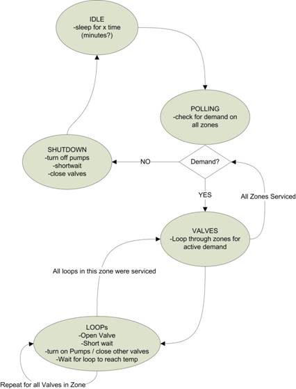
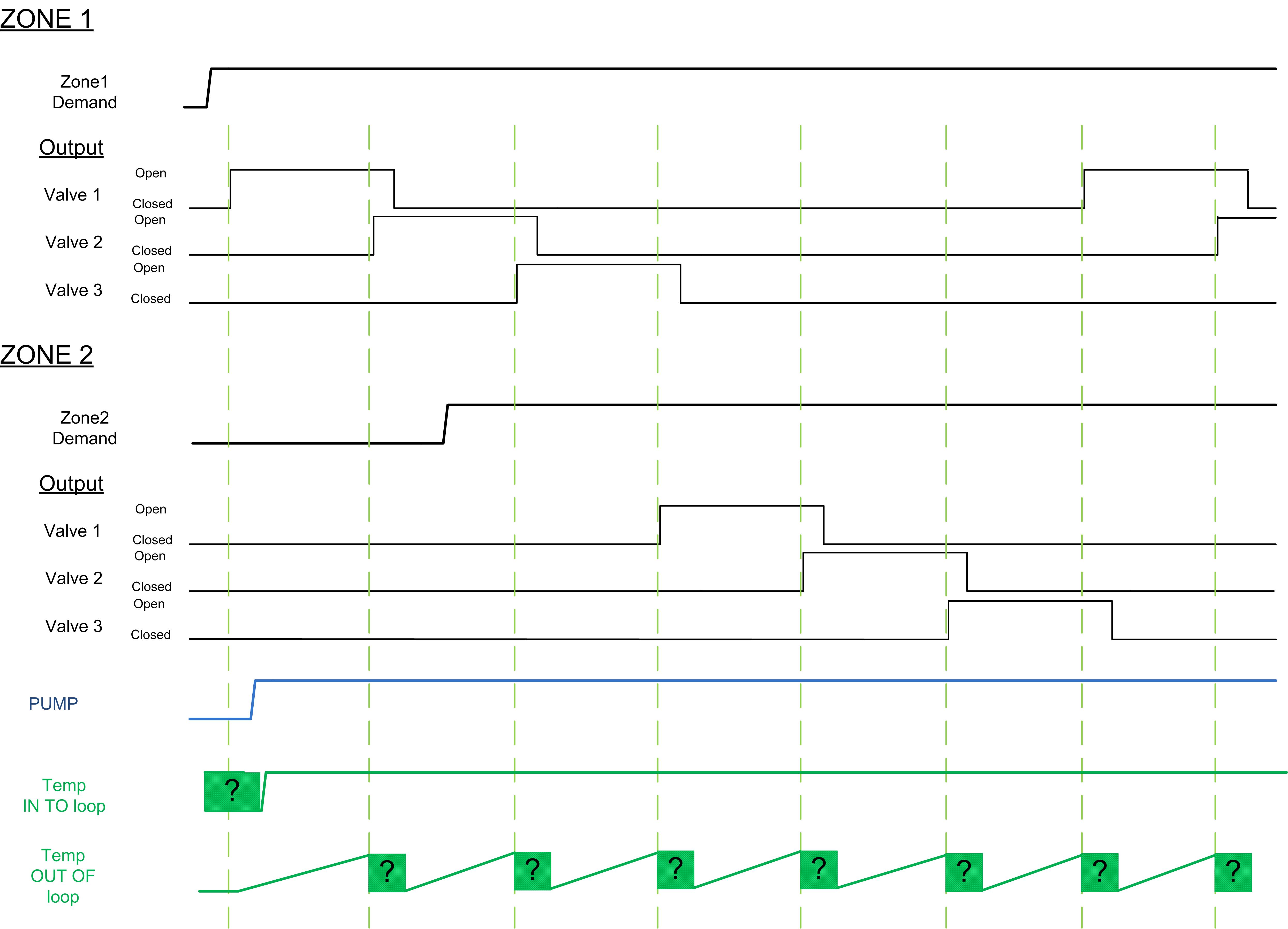
When there is active demand for heat in the home, the inside pump is kept on to prevent short cycling. Because it is kept on it was important that we ensure there are always at least one valve open while it is on. The timing diagram in Figure 5 shows how valves are activated one at time while ensuring at least one is opened while the pump is running. Also shown in this diagram (in green) once the loop is warm, a transition to the next valve begins. The temperature is unknown at the transition points when more than one valve is opened.
Figure 5 - Valve Timing
In addition to the inside heat control system, there is a heat exchanger which is used to supplement the Domestic Hot Water demands. It does this by preheating the cold water coming out of the well prior to it going into the Hot Water Heater. The new functionality of this controller simply monitors a thermocouple that is located near the domestic hot water heat exchanger. When that temperature drops below a threshold (indicating water is flowing from in from the well) we turn on the outside pump to heat up that exchanger.
Finally, there were two safety features added to the new system. First, a Pressure sensor was placed into the main line inside the house. This will allow detection of a leak inside the system. If a leak is detected, we immediately shut down the valves and inside pump to reduce the amount of fluid that may be lost into the walls/ceiling of the house. Second, the flow meter will be monitored to ensure water is moving and detect any blockage that may occur. One example of this occurring would be if a valve failed to open. Once we open a valve and turn on the pumps fluid should be flowing and so we should have pulses being sent in to us. If we do not see these pulses after opening a valve, then we can declare a blockage has occurred.
Hardware/software
tradeoffs
The only tradeoff that was done for this project was to use the 8MHz Oscillator that is internal to the device. I have pads on the board for an external oscillator but chose not to use it. The only timing constraint we have is to process the BTU calculation each time a pulse is detected from the flow meter. The flow meter (FTB4607) puts out 75 pulses/gallon and we expect up to 8gallons/min. This means that we could have up to 600 pulses/min OR 1 pulse every 10msec. The 8MHz is plenty fast for the relatively slow operation we are performing and exact timing is not critical.
Relationship to
available standards
The only standard that is applicable to this design is the RS232 serial protocol. In order to comply with this I used the built microchip USART functions and a MAX232 serial transceiver to translate the protocol out to logic levels that a PC could interpret.
Discuss existing
patents, copyrights, trademarks relevant to project
There are multiple different devices for controlling heat systems. These devices are very expensive and I was not able to locate any one unit that could control the pumps, valves, and also have real time data sent to a PC interface. It would take two or three different devices to perform the controls that this microprocessor is doing. Some designs obtain control over the system by placing a pump dedicated to each zone or even each loop! Since these pumps are in the $300 range, that could get expensive very fast. The parts necessary for this controller cost less than adding one additional pump.
Industrial applications have controls similar to this design but there is nothing at a small scale for residential use. The industrial controllers typically take a room full of equipment and many thousands of dollars to implement.
Word of mouth has sparked multiple people to express interest in this low cost solution to decreasing their wood and electric consumption. So far I do not have data to show how much the actual savings will be but have many people curious of the results this will yield. Hopefully one year from now I will have that data once the system is operational in a home. At this point in time I do feel that there is a market for this type of low cost, residential controller but I don’t really know how to pursue it further.
Things that were
tricky
The first tricky thing that I encountered during this project was building the demo board. Because the design was very simple – (3) IC’s, some switches, LEDs and a hand full of discrete components I decided to etch my own board. The board layout was pretty straight forward and the chemical etching wasn’t very difficult. But, after the board was etched and populated I had to debug the non functional board that resulted. Several issues were easily found using a digital multi-meter, like direct shorts and grounds. Then, to make it even more interesting, I was using all new development tools. So when I was not able to program the first test code, it was hard to tell if it was a board problem or my error using the tools. After a few frustrating days it turned out to be a bit of both.
Things that didn’t
worked
The first thing that didn’t work was the internal pull-ups on the device. When I was drafting the board layout, I scanned the data sheet of the device to see if it supported internal pull-ups. But once I was developing the code I found that the switches that were simulating the thermostat demand were intermittent. As I pursued this further I found that the device only supported weak pull-ups on Port B and I was using switches on multiple Ports. I should have been more careful about the upfront review of the datasheet. So, it required a few extra resistors to be tacked onto the board in order to stabilize the switch values.
The other thing that didn’t work very well was my insertion of “vias”. In an attempt to utilize a ground plane on my board I left plenty of locations for a small piece of wire to be soldered on both side to create an electrical connection between the two layers of copper. I got into trouble in a couple areas because I populated several larger footprint components (i.e. sockets) prior to soldering all of my vias into place. Because of this, I was unable to get all of the “vias” populated and had to resort to several soft wires routed around the board. Next time I will remember to populate all those little via wires before anything else.
Usability by you
and other people
This prototype has a crude data output to a serial connection. The idea is for that data to be pulled into a PC to be analyzed. It is not very elegant but I think it gets the job done. As for modifying logic or reprogramming, this system is not usable by the general public. Currently, the only way to modify any logic is to dig into the source code and recompile then reprogram the device. This is acceptable because I intend to be the only person modifying any code so there isn’t a need for an elaborate interface.
Program/Hardware
Design
This phase of the project was focused on building a prototype that could control a residential heat system. The prototype had a couple of purposes: low cost/ low risk way of obtaining proof of concept and of developing the software. All of the interfaces were simulated with simple switches, potentiometers, and LEDs. The prototype board was also a convenient way to demonstrate to the professor what I’ve been working on for the last month.
The software environment used for this phase of the project was MPLAB IDE v8.63 with a MCC18 compiler and a PICkit 2 programmer/debugger. All of the code written was in the c language and targeted the PIC 18F4520 microcontroller which resided on a custom PCB. The code was organized into the following main program and subroutines.
· Void main(); - At power on, the system is initialized and goes into an infinite loop. The bulk of the this logic is a large arbiter to decide which valves pumps to turn on. Intertwined in this arbiter are the desired timing delays and usart commands as well as the safety checks for pressure and flow.
· Initialize(); - This routine only runs one time to bring the system to a known state at power on.
· Short_delay(); - This routine is a simple delay that is called many times throughout the main code. The primary reason for this delay is to allow a short period of time for physical devices to respond to software commands. For example: Valves to open or close, or fluid to start moving through a loop where it can be measured with the flow meter.
· Long_delay(); - This routine is a simple delay that is called many times throughout the main code. The primary reason for this longer delay is to allow time for things to warm up before sampling them again or before moving on to another state.
· Shutdown(); - This routine is a graceful way to shutdown the flow of fluid in the house. It turns off the inside pump, then after a short delay, closes all the valves. This is desirable because it could be detrimental to have all the valves closed while the pump is still running.
· sampleADC(); - This routine samples all the thermocouples in the system. It is called throughout the main to understand what is going on in the system. This information is them transmitted to the serial terminal for further analysis.
· InterruptHandlerHigh(); - This is the routine to handle the loss of pressure in the system. If pressure loss is detected it shuts the system down and goes into an endless loop to prevent additional damage. I recommend placing an alarm/buzzer on the next board which will be activated while in this endless loop.
The next phase of the project involves designing the final board and ultimately integrating it into the house. This will be almost exclusively a hardware task of converting the real world interfaces into a 5v logic level that the microcontroller needs to communicate. There is pretty good confidence in the software at this phase, so I anticipate only minor adjustments going forward. There are several types of interfaces that need to be converted into the 5v logic: thermostats, thermocouples, flow meter, pressure switch, valves, and pumps.
INPUTS
Thermostats operate at 24VAC. These will be directly converted into logic with a MID400.
Thermocouples (Type E) operate at very low voltages and will need to be amplified and or voltage shifted in order for the microcontroller to properly read them. Each of these will need to be calibrated once it’s in the system to ensure we have accurate measurements for calculating BTUs.
Flow Meter (FTB4607) operates between 6-16VDC. A 4N35 optocoupler will be used to bridge this onto the control board where it will be pulled up when inactive.
Pressure switch (Mercoid A6-3532221) will be pulled up/down on the board.
OUTPUTS
Valves will be controlled by using a LM358 op amp to drive a power FET (IRF1310). Similarly, motors will be controlled by using an opamp to drive a FET which switches a solid state relay.
Results
Because I only have the prototype demonstration unit so far, I do not have any tangible data for the efficiency improvements that we are going after. I am confident that there will be some cost savings due to the implementation of this controller. The magnitude of those savings is not very clear at this point. To estimate the savings I will describe the changes and their expected impact.
1. In the old system the outside pump ran constantly during the wood burning months. The new system is smart enough to only turn on that pump when there is demand for domestic hot water or heat into the home. The amount of that demand is very difficult thing to gauge because of the multiple factors that contribute to it: outside air temp, number of occupants, thermostat settings etc… My first estimation would say that the pump would run 50% of the time over the course of the winter. So, although it may be pennies per day, over the course of the winter this could add up to a measureable amount of savings.
![]()
2. The old system would open any valves into zones requesting heat and leave them all open until the zone demand went away. The first problem with this is that the flow rate for each loop decreases as the number of valves opens. This means that it will take a longer time for each of them to warm up and start inserting energy into the living space above. Also, once the loops do warm up, the pump is still constantly running but just to cycle hot fluid. In other words, there is more energy being wasted to run the pump than there is energy going into the living space. The second improvement of this heat controller is the advanced control of the interior pump and heating valves. Specifically, we now only turn on one valve at a time and cycle to the next valve once the first one warms up. This means that the single loop of fluid will rapidly warm up and then the valves will switch to the next loop where that one will warm up. After all the loops have been serviced, the valves can then return to the first zone that has started to cool and it will be warmed back up. I don’t have much data to back this but my estimation is that this will have about a 10-15% decrease in the run time of the pump.
![]()
3. The old system would provide heat to the attic 20 minutes out of every hour regardless of the need for it. The purpose of this heat is to prevent condensation from forming when the air handler mixes air from inside and outside the house. The heat only needs to be sent to that location when there is a potential for condensation – air handler is on and the temperature/humidity difference between the outside and inside air. So, the new system monitors the air handler activity as well as a thermostat to decide when to send heat to that location. It is estimated that the air handler only runs 5% of the day. Couple this will the fact that condensation is only a major problem when the temperature in the well insulated attic drops below 50degrees. So, in the fall and spring when outside air temperature is mild, there would be no demand for heat in that zone. This would result in an absolute savings of 30%. However, in the heart of the winter, when heat is needed up there it will only be sent when the air handler turns on. So as a ballpark idea, I would split the difference and say this could result in another 10-15% savings.
![]()
4. The final savings that I have not discussed is the potential to reduce the amount of fuel needed to heat the house. This will be a result of all the previously mentioned improvements. The less time there is energy being removed from the boiler, the less fuel will need to be burned. I don’t have a dollar figure for this because all the wood is harvested off the property but you can imagine the benefit of having less wood to harvest, move and store. As well as the potential for less time needed to feed fuel into the boiler.
5. There are also several minor improvements to power savings that come from removing the current PLC controller and its three power supplies from the system. This microcontroller board will draw a fraction of the electricity as compared to that large unit.
In summary, the rough estimates provided sum up to almost $100/year. This means that the controller will not make you rich; however, I do believe that it will pay for itself in short period of time.
Conclusion
How did it meet
expectations? What would be done different?
Because this was meant to be a first prototype for demonstration, I am very happy with the functionality I was able to develop and test. There were also several lessons learned from this design that will be taken into account for final board. These changes include: leaving a little more room for the program header, master clear button, and any other things that need to be accessed by a person after the board is operational.
Did design conform
to applicable standards
Yes, this design conformed to the applicable standard of RS232 protocol. This was verified by it displaying useful information onto a Putty console.
Intellectual
Property
This design was all new and did not contain any reuse or borrowing of other design efforts. As stated in the introduction of this document, my friend Ron Shoemaker was the originator of this project idea. He had a vision of things he wanted to do to improve his current system and needed someone to implement it. This academic project has brought his ideas closer to reality.
As for potential patent and/or publications, yes, I think this topic may be worthy of some consideration. Mostly I think there is a large market for a low cost solution to improve the efficiency of residential boiler systems.
Ethical
considerations (>200 words on IEEE code of ethics)
The development of this project was compliant to the IEEE code of ethics. There were two aspects of the code which did not become relevant to this design effort (2, 4) because there was no element of conflict of interest or potential for bribery.
A couple of the declarations in this code (1 & 9) relate to the safety and well being. Aligned with these declarations two safety features were added to the design which will help protect the people and property where this heat control system would be implemented.
Another important aspect of this code (6 & 10) relates to the improving technical competence and assisting colleagues. This project was done for a fellow engineer who did not have the programming experience that I have received. However he has far more experience with the other aspects of this system. The diversity of our experiences combined to produce a functional prototype which we intend to pursue to the next level of integrating into his house. During the evolution of this project, we were up front and honest about our knowledge base. There were several occasions where we did not immediately have the answer but were able to locate the information necessary for success.
The honesty and desire to expand our technological knowledge is in direct alignment of the ieee code of ethics.
Legal
considerations
The demonstration board that was built for this project does not have any legal restrictions/considerations.
Source Code
#include <p18f4520.h>//points to the device library so the compiler can interpret registers
#include <portb.h>
#include <usart.h>
#include <ADC.h>
#include <stdlib.h>
#include <stdio.h>
#include <delays.h>
//device configuration
#pragma config WDT = OFF //disable watchdog timer
#pragma config OSC = INTIO67 //setup internal Osc @ 31kHz
#pragma config MCLRE = ON //MCLR pin enabled (normal)
#pragma config PBADEN = OFF //makes PortB digital i/o
#pragma config LVP = OFF //disables low voltage programming (mode doesn't need PGM)
//assign pins to variables (for our sanity)
//digital outputs:
#define pump1 PORTDbits.RD0 //inside
#define pump2 PORTDbits.RD1 //outside
#define valve1 PORTBbits.RB5 //Zone 1 V1
#define valve2 PORTBbits.RB4 //Zone 1 V2
#define valve3 PORTBbits.RB3 //Zone 1 V3
#define valve4 PORTBbits.RB2 //Zone 2 V1
#define valve5 PORTBbits.RB1 //Zone 2 V2
#define valve6 PORTDbits.RD7 //Zone 3 V1
#define valve7 PORTDbits.RD6 //Zone 3 V2
#define valve8 PORTDbits.RD5 //Zone 4 V1
#define valve9 PORTCbits.RC5 //Zone 5 V1
#define valve10 PORTCbits.RC4 //Zone 5 V2
//inputs:
#define tcouple1 PORTAbits.RA0 //AN0 //analog -Outside input sensor
#define tcouple2 PORTAbits.RA1 //AN1 //analog -Outside output sensor
#define tcouple3 PORTAbits.RA2 //AN2 //analog -Inside input sensor
#define tcouple4 PORTAbits.RA3 //AN3 //analog -Inside output sensor
#define tcouple5 PORTAbits.RA5 //AN4 //analog -Attic Sensor
#define flow_meter PORTAbits.RA4 //T0CKI //counter -Safety to prevent pump from burning up
#define tstat1 PORTCbits.RC3 //digital -Zone1 demand
#define tstat2 PORTCbits.RC2 //digital -Zone2 demand
#define tstat3 PORTCbits.RC1 //digital -Zone3 demand
#define tstat4 PORTCbits.RC0 //digital -Zone4 demand
#define air_sw PORTDbits.RD3 //spare switches -Zone5 demand
#define press_sw PORTBbits.RB0 //int0 -Safety for pipe blowout/leak
#define sw6 PORTDbits.RD2 //spare switches -spare
//words easier to see than curly braces
#define begin {
#define end }
//instantiation of all our functions
void initialize(void); //initial power up settings
void short_delay (void); //for Valve/Pump switching
void long_delay (void); //for loops to warm up
void sys_idle(void); //when no demand we can rest
void shutdown(void); //gracefully shut down system
void sampleADC(void); //record current tcouple values
void InterruptHandlerHigh (void); //process Pressure Switch interrupt
//our variables:
unsigned char attic_demand ;//calculation for preventing condensation
char Zdemand ;//1=A zone requests heat; 0=No zones request heat
unsigned char SystemOn ;//1=Currently heating, 0=new heating
unsigned char tstat_sel ;//used to define which tstat to sample
unsigned int tstat_num[6] ;//most recent sample temp of each tcouple ([0] not used)
int oldflowcount ;//last flow count to compare against
//----------------------------------------------------------------------------
//----------------------------------------------------------------------------
// High priority interrupt vector
#pragma code InterruptVectorHigh = 0x08
void
InterruptVectorHigh (void)
begin
_asm
goto InterruptHandlerHigh //jump to interrupt routine
_endasm
end
// High priority interrupt routine
#pragma code
#pragma interrupt InterruptHandlerHigh
void
InterruptHandlerHigh ()
begin
shutdown();
putrsUSART( "ERROR: Pressure lost! System shut down.\n\r" );
INTCONbits.INT0IF = 0; //clear interrupt flag
while(1)//stick in this loop until system is reset
begin
putrsUSART( "ERROR: Pressure lost! Shutting Down system.\n\r" );
//recommend putting in a buzzer here to notify houshold of failure
end//while(1)
// end//if(INT0IF)
end//interrupthandlerHigh
//----------------------------------------------------------------------------
//----------------------------------------------------------------------------
void main (void)
begin
//initialize the system to a known state
initialize();
putrsUSART("System Initialized.\n\r\n\r");
while (1)
begin
//****test area*******************
//****test area*******************
sampleADC();
attic_demand = ( air_sw && ( tstat_num[5] < 50 ) );
Zdemand = (tstat1 | tstat2 | tstat3 | tstat4 | attic_demand);
short_delay();
if(Zdemand==0)//no zones demand heat
begin
//check domestic hot water******************************//*
//*
if( tstat_num[2] < 100 ) //domestic water is cold //*
begin //*
//*
pump2 = 0;//turn on pump2 //*
//*
end //*
if( tstat_num[2] > 115 ) //domestic water is hot //*
begin //*
//*
pump2 = 1;//turn off pump2 //*
//*
end //*
//end domestic hot water section************************//*
putrsUSART( "No Demand found.\n\r" );
shutdown();//ensure everything is off
sys_idle();
end
else//service the zones
begin
//******************************************************************************
//******************************************************************************
if(tstat1)
begin
putrsUSART( "\n\rZone 1 requested heat.\n\r" );
oldflowcount = TMR0L;//samples counter for later comparison
valve1 = 0;//open Valve 1
putrsUSART( "Zone 1 Valve 1 opened.\n\r" );
short_delay();//wait for valve to open
valve2 = 1;//turn off all the other valves
valve3 = 1;
valve4 = 1;
valve5 = 1;
valve6 = 1;
valve7 = 1;
valve8 = 1;
valve9 = 1;
valve10 = 1;
if(pump1)//inside pump is off
begin
pump1 = 0;
putrsUSART( "Pump 1 turned on.\n\r" );
end
if(pump2)//outside pump is off
begin
pump2 = 0;
putrsUSART( "Pump 2 turned on.\n\r" );
end
if (oldflowcount == TMR0L)//blockage detected
begin
shutdown();
putrsUSART( "ERROR: Blockage detected! Shutting Down system.\n\r" );
while(1){};
end;
long_delay();//let loop warm up
sampleADC();
while( (tstat_num[4] < 110 ) )//wait for loop to warm up
begin
long_delay();
sampleADC();
end
if(!valve1)//valve 1 is on
begin
oldflowcount = TMR0L;//samples counter for later comparison
valve2 = 0;//open Valve 2
putrsUSART( "Zone 1 Valve 2 opened.\n\r" );
short_delay();//wait for valve to open
valve1 = 1;//turn off all the other valves
valve3 = 1;
valve4 = 1;
valve5 = 1;
valve6 = 1;
valve7 = 1;
valve8 = 1;
valve9 = 1;
valve10 = 1;
end
if (oldflowcount == TMR0L)//blockage detected
begin
shutdown();
putrsUSART( "ERROR: Blockage detected! Shutting Down system.\n\r" );
while(1){};
end;
long_delay();//let loop warm up
sampleADC();
while( (tstat_num[4] < 110 ) )//wait for loop to warm up
begin
long_delay();
sampleADC();
end
if(!valve2)//valve 2 is currently on
begin
oldflowcount = TMR0L;//samples counter for later comparison
valve3 = 0;//open Valve 3
putrsUSART( "Zone 1 Valve 3 opened.\n\r" );
short_delay();//wait for valve to open
valve1 = 1;//turn off all the other valves
valve2 = 1;
valve4 = 1;
valve5 = 1;
valve6 = 1;
valve7 = 1;
valve8 = 1;
valve9 = 1;
valve10 = 1;
end
if (oldflowcount == TMR0L)//blockage detected
begin
shutdown();
putrsUSART( "ERROR: Blockage detected! Shutting Down system.\n\r" );
while(1){};
end;
long_delay();//let loop warm up
sampleADC();
while( (tstat_num[4] < 110 ) )//wait for loop to warm up
begin
long_delay();
sampleADC();
end
putrsUSART( "Zone 1 has been serviced\n\r" );
end//Zone 1 has been serviced
//******************************************************************************
//******************************************************************************
if(tstat2)
begin
putrsUSART( "\n\rZone 2 requested heat.\n\r" );
oldflowcount = TMR0L;//samples counter for later comparison
valve4 = 0;//open Valve 4
putrsUSART( "Zone 2 Valve 1 opened.\n\r" );
short_delay();//wait for valve to open
valve1 = 1;//turn off all the other valves
valve2 = 1;
valve3 = 1;
valve5 = 1;
valve6 = 1;
valve7 = 1;
valve8 = 1;
valve9 = 1;
valve10 = 1;
if(pump1)//inside pump is off
begin
pump1 = 0;
putrsUSART( "Pump 1 turned on.\n\r" );
end
if(pump2)//outside pump is off
begin
pump2 = 0;
putrsUSART( "Pump 2 turned on.\n\r" );
end
if (oldflowcount == TMR0L)//blockage detected
begin
shutdown();
putrsUSART( "ERROR: Blockage detected! Shutting Down system.\n\r" );
while(1){};
end;
long_delay();//let loop warm up
sampleADC();
while( (tstat_num[4] < 110 ) )//wait for loop to warm up
begin
long_delay();
sampleADC();
end
if(!valve4)//valve 4 is currently on
begin
oldflowcount = TMR0L;//samples counter for later comparison
valve5 = 0;//open Valve 2
putrsUSART( "Zone 2 Valve 2 opened.\n\r" );
short_delay();//wait for valve to open
valve1 = 1;//turn off all the other valves
valve2 = 1;
valve3 = 1;
valve4 = 1;
valve6 = 1;
valve7 = 1;
valve8 = 1;
valve9 = 1;
valve10 = 1;
end
if (oldflowcount == TMR0L)//blockage detected
begin
shutdown();
putrsUSART( "ERROR: Blockage detected! Shutting Down system.\n\r" );
while(1){};
end;
long_delay();//let loop warm up
sampleADC();
while( (tstat_num[4] < 110 ) )//wait for loop to warm up
begin
long_delay();
sampleADC();
end
putrsUSART( "Zone 2 has been serviced\n\r" );
end//Zone 2 has been serviced
//******************************************************************************
//******************************************************************************
if(tstat3)
begin
putrsUSART( "\n\rZone 3 requested heat.\n\r" );
oldflowcount = TMR0L;//samples counter for later comparison
valve6 = 0;//open Valve 1
putrsUSART( "Zone 3 Valve 1 opened.\n\r" );
short_delay();//wait for valve to open
valve1 = 1;//turn off all the other valves
valve2 = 1;
valve3 = 1;
valve4 = 1;
valve5 = 1;
valve7 = 1;
valve8 = 1;
valve9 = 1;
valve10 = 1;
if(pump1)//inside pump is off
begin
pump1 = 0;
putrsUSART( "Pump 1 turned on.\n\r" );
end
if(pump2)//outside pump is off
begin
pump2 = 0;
putrsUSART( "Pump 2 turned on.\n\r" );
end
if (oldflowcount == TMR0L)//blockage detected
begin
shutdown();
putrsUSART( "ERROR: Blockage detected! Shutting Down system.\n\r" );
while(1){};
end;
long_delay();//let loop warm up
sampleADC();
while( (tstat_num[4] < 110 ) )//wait for loop to warm up
begin
long_delay();
sampleADC();
end
if(!valve6)//valve 6 is currently on
begin
oldflowcount = TMR0L;//samples counter for later comparison
valve7 = 0;//open Valve 2
putrsUSART( "Zone 3 Valve 2 opened.\n\r" );
short_delay();//wait for valve to open
valve1 = 1;//turn off all the other valves
valve2 = 1;
valve3 = 1;
valve4 = 1;
valve5 = 1;
valve6 = 1;
valve8 = 1;
valve9 = 1;
valve10 = 1;
end
if (oldflowcount == TMR0L)//blockage detected
begin
shutdown();
putrsUSART( "ERROR: Blockage detected! Shutting Down system.\n\r" );
while(1){};
end;
long_delay();//let loop warm up
sampleADC();
while( (tstat_num[4] < 110 ) )//wait for loop to warm up
begin
long_delay();
sampleADC();
end
putrsUSART( "Zone 3 has been serviced\n\r" );
end//Zone 3 has been serviced
//******************************************************************************
//******************************************************************************
if(tstat4)
begin
putrsUSART( "\n\rZone 4 requested heat.\n\r" );
oldflowcount = TMR0L;//samples counter for later comparison
valve9 = 0;//open Valve 1
putrsUSART( "Zone 4 Valve 1 opened.\n\r" );
short_delay();//wait for valve to open
valve1 = 1;//turn off all the other valves
valve2 = 1;
valve3 = 1;
valve4 = 1;
valve5 = 1;
valve6 = 1;
valve7 = 1;
valve8 = 1;
valve10 = 1;
if(pump1)//inside pump is off
begin
pump1 = 0;
putrsUSART( "Pump 1 turned on.\n\r" );
end
if(pump2)//outside pump is off
begin
pump2 = 0;
putrsUSART( "Pump 2 turned on.\n\r" );
end
// end
if (oldflowcount == TMR0L)//blockage detected
begin
shutdown();
putrsUSART( "ERROR: Blockage detected! Shutting Down system.\n\r" );
while(1){};
end;
long_delay();//let loop warm up
sampleADC();
while( (tstat_num[4] < 110 ) )//wait for loop to warm up
begin
long_delay();
sampleADC();
end
if(!valve9)//valve 8 is currently on
begin
oldflowcount = TMR0L;//samples counter for later comparison
valve10 = 0;//open Valve 2
putrsUSART( "Zone 3 Valve 2 opened.\n\r" );
short_delay();//wait for valve to open
valve1 = 1;//turn off all the other valves
valve2 = 1;
valve3 = 1;
valve4 = 1;
valve5 = 1;
valve6 = 1;
valve7 = 1;
valve8 = 1;
valve9 = 1;
end
if (oldflowcount == TMR0L)//blockage detected
begin
shutdown();
putrsUSART( "ERROR: Blockage detected! Shutting Down system.\n\r" );
while(1){};
end;
long_delay();//let loop warm up
sampleADC();
while( (tstat_num[4] < 110 ) )//wait for loop to warm up
begin
long_delay();
sampleADC();
end
putrsUSART( "Zone 4 has been serviced\n\r" );
end//Zone 4 has been serviced
//******************************************************************************
//******************************************************************************
if( attic_demand )//this loop prevents condensation in attic
begin
putrsUSART( "\n\rZone 5 requested heat.\n\r" );
oldflowcount = TMR0L;//samples counter for later comparison
valve8 = 0;//open Valve 1
putrsUSART( "Zone 5 Valve 1 opened.\n\r" );
short_delay();//wait for valve to open
valve1 = 1;//turn off all the other valves
valve2 = 1;
valve3 = 1;
valve4 = 1;
valve5 = 1;
valve6 = 1;
valve7 = 1;
valve9 = 1;
valve10 = 1;
if(pump1)//inside pump is off
begin
pump1 = 0;
putrsUSART( "Pump 1 turned on.\n\r" );
end
if(pump2)//outside pump is off
begin
pump2 = 0;
putrsUSART( "Pump 2 turned on.\n\r" );
end
if (oldflowcount == TMR0L)//blockage detected
begin
shutdown();
putrsUSART( "ERROR: Blockage detected! Shutting Down system.\n\r" );
while(1){};
end;
long_delay();
sampleADC();
putrsUSART( "Zone 5 has been serviced\n\r" );
end//Zone 5 has been serviced
end//if (Zdemand)
end//while(1)
end//main
//initialize all the stuff for power up
void initialize(void)
begin
printf(stdout,"%dSystem Initializing\n\r\n\r");
OSCCONbits.IRCF0 = 1;
OSCCONbits.IRCF1 = 1;
OSCCONbits.IRCF2 = 1; //8Mhz internal oscillator
while(!OSCCONbits.IOFS); //wait for oscillator to stabilize
// RCSTAbits.SPEN = 1;
//setup for INT0 (Pressure Switch)
INTCONbits.GIE = 1; //enables all global interrupts
INTCONbits.INT0IE = 1; //enables INT0 from external source
INTCON2bits.INTEDG0 = 0; //interrupt on rising edge of INT0 pressure switch
//setup Flow Meter (Timer0)
T0CON = 0xB8;
INTCONbits.TMR0IE = 0; //disable interrupt when ovflow
//setup port directions
TRISA = 0xFF;//port direction
TRISB = 0xC1;//port direction
TRISC = 0xCF;//port direction
TRISD = 0x1C;//port direction
//USART setup
OpenUSART(USART_TX_INT_OFF & //USART config
USART_RX_INT_OFF &
USART_ADDEN_OFF &
USART_ASYNCH_MODE &
USART_EIGHT_BIT &
USART_CONT_RX &
USART_BRGH_LOW, 12); //9600 baud rate
//initial value of internal params
SystemOn = 0;
shutdown();
end
//simple delay tasks for testing (uses ticks not seconds)
void short_delay (void)//short time for valve transitions
begin
Delay1KTCYx(1000);
end//shortdelay
void long_delay (void)//long time to heat up loop
begin
Delay10KTCYx(100000);
end//longdelay
//gracefully turn the system off
void shutdown(void)
begin
pump1 = 1;
// pump2 = 1;//domestic water will continue to run
short_delay();//short delay to wait for pumps to stop
valve1 = 1;//close all valves
valve2 = 1;
valve3 = 1;
valve4 = 1;
valve5 = 1;
valve6 = 1;
valve7 = 1;
valve8 = 1;
valve9 = 1;
valve10 = 1;
end
void sys_idle(void)
begin
long_delay();
long_delay();
long_delay();
long_delay();
long_delay();
long_delay();
end//sys_idle
//sample tstats
void sampleADC(void)
begin
unsigned int adc_result ;//temporary assignment from adc
char i;
OpenADC(ADC_FOSC_RC & ADC_RIGHT_JUST & ADC_12_TAD,ADC_CH0 & ADC_INT_OFF, 0); //open adc port for reading
ADCON1 =0x09; //set VREF+ to VDD and VREF- to GND (VSS)
for (i = 1; i < 6; i++)
begin
switch(i)
begin
case 1:
SetChanADC(ADC_CH0); //tstat1
Delay10TCYx(5);
ConvertADC(); //perform ADC conversion
while(BusyADC()); //wait for result
adc_result = ReadADC(); //get ADC result
Delay10TCYx(5);;
break;
case 2:
SetChanADC(ADC_CH1); //tstat2
Delay10TCYx(5);
ConvertADC(); //perform ADC conversion
while(BusyADC()); //wait for result
adc_result = ReadADC(); //get ADC result
Delay10TCYx(5);
break;
case 3:
SetChanADC(ADC_CH2); //tstat3
Delay10TCYx(5);
ConvertADC(); //perform ADC conversion
while(BusyADC()); //wait for result
adc_result = ReadADC(); //get ADC result
Delay10TCYx(5);
break;
case 4:
SetChanADC(ADC_CH3); //tstat4
Delay10TCYx(5);
ConvertADC(); //perform ADC conversion
while(BusyADC()); //wait for result
adc_result = ReadADC(); //get ADC result
Delay10TCYx(5);
break;
case 5:
SetChanADC(ADC_CH4); //tstat5
Delay10TCYx(5);
ConvertADC(); //perform ADC conversion
while(BusyADC()); //wait for result
adc_result = ReadADC(); //get ADC result
Delay10TCYx(5);
break;
default:
// SetChanADC(ADC_CH0); //tstat1
break;
end//case
if(i<5)//water system tcouples
begin
//adc_result = 0-1000; Temp range is 60-180degF
tstat_num[i] = ( (adc_result/8) + 60);//scale value
end
else//attic tcouple
begin
//adc_result = 0-1000; Temp range is 0-100degF
tstat_num[i] = ( (adc_result/10));//scale value
end
fprintf(stdout, "Tcouple #%#i", i);
fprintf(stdout, ": %#i", tstat_num[i]);
fprintf(stdout, " DegF\n\r");
end//for loop
CloseADC();//done using it
end
Schematics
Figure 6 - Demo Board Layout
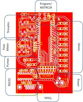
Figure 7 - Demo Board Schematic
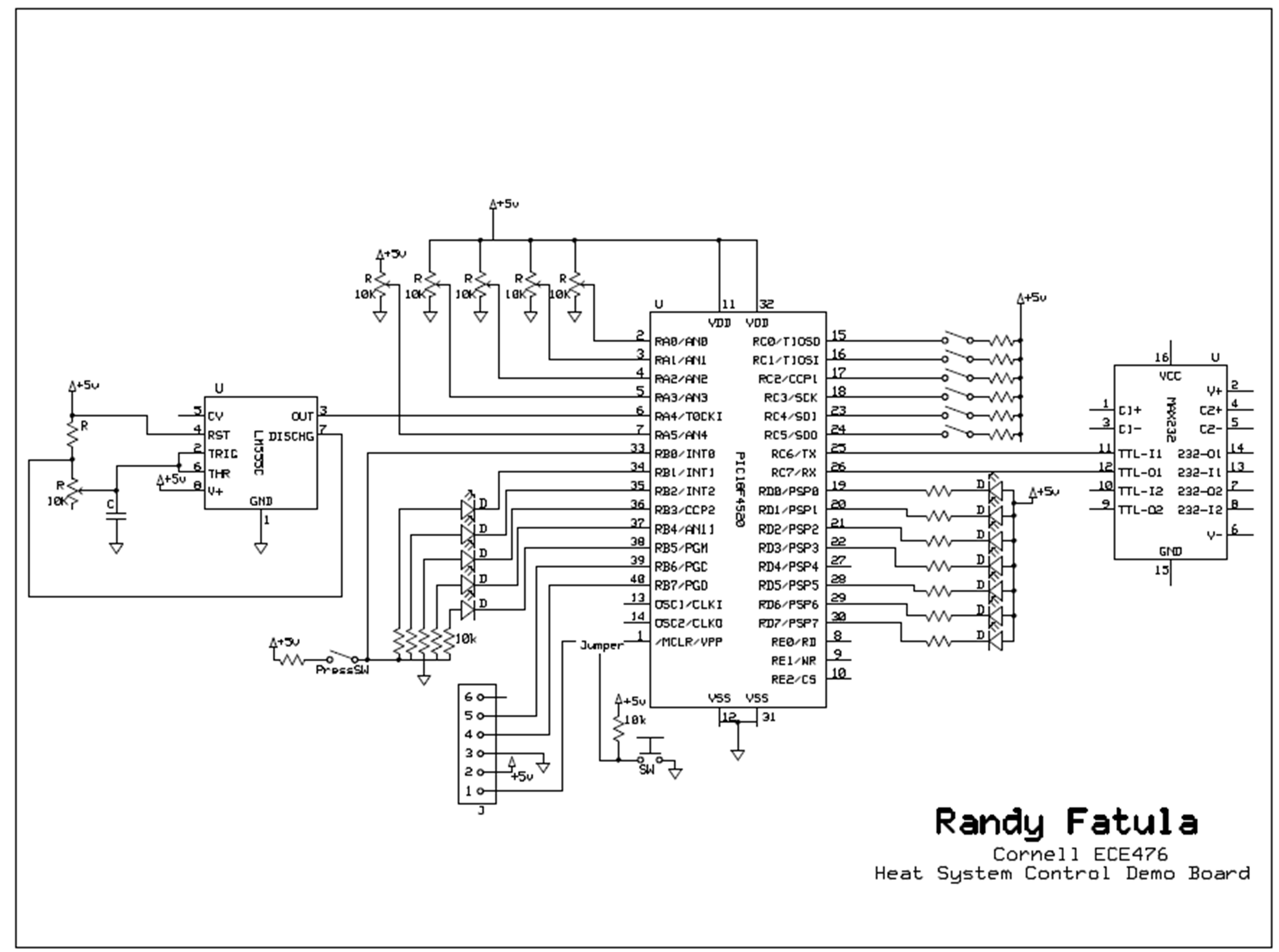
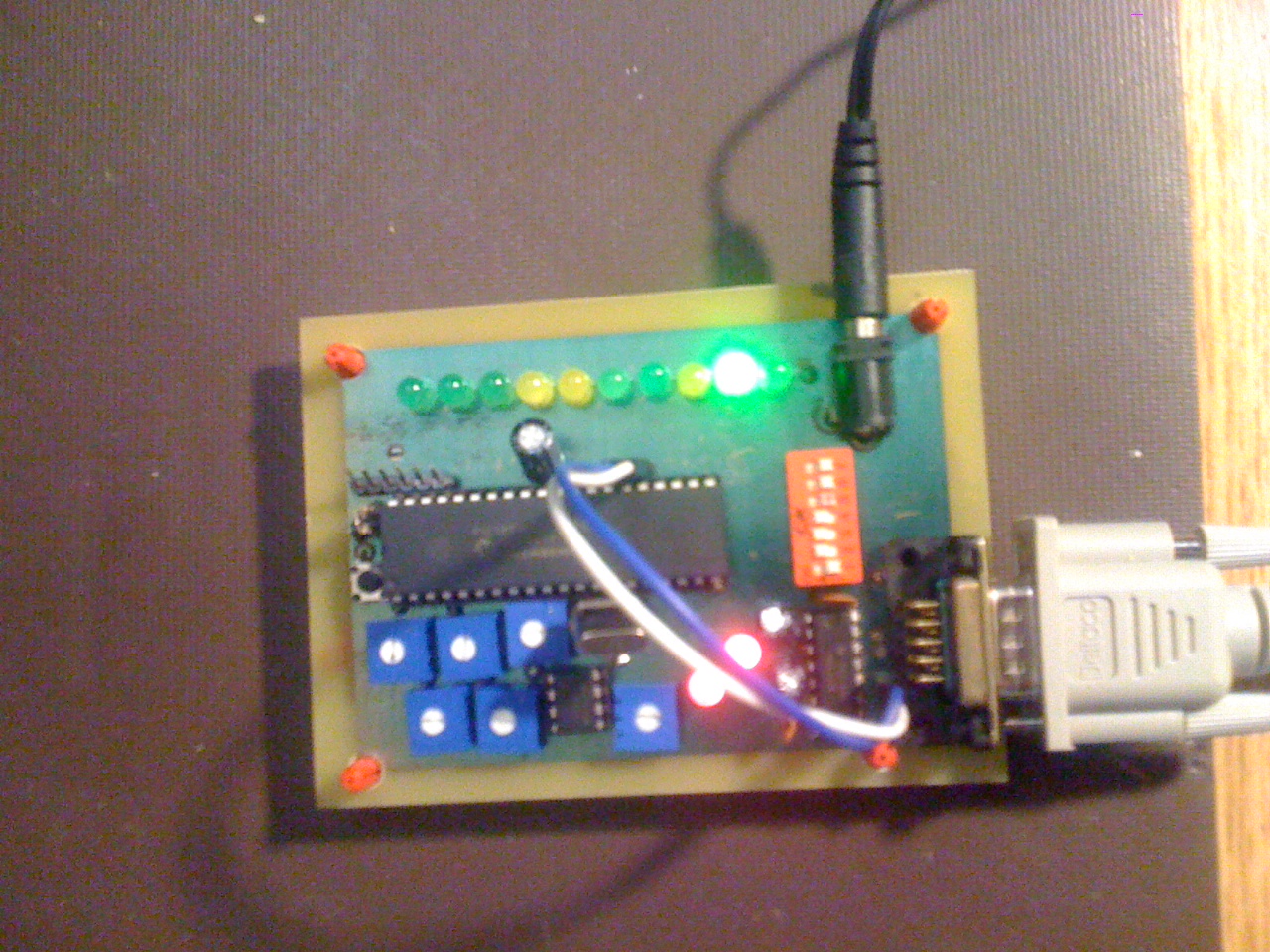
Figure 8 - Demo Prototype
Cost / BOM
· (1) 4”x6” Doublesided Presensitized 1oz copper $11.14 (Digikey PC61P-ND )
· (1) MAX232 Serial Driver $1.16 (Digikey 296-1402-5-ND)
· Etching Chemicals $FREE – reused from previous project
· (6) 10k TrimPots $FREE – lab asset
· (12) LEDs $FREE – lab asset
· (1) PIC 18F4520 $FREE – leftover parts bin**
· (1) 555 Timer $FREE – leftover parts bin**
· (1) DB9 Connector $FREE – leftover parts bin **
· (1) Pushbutton Switch $FREE – leftover parts bin**
· (1) 7 port Switch Bank $FREE – leftover parts bin**
· (1) +5V Power Supply and Connector $FREE – leftover parts bin**
· Multiple Resistors $FREE – leftover parts bin**
· Multiple Capacitors $FREE – leftover parts bin**
· Male Headers $FREE – leftover parts bin**
· Two wire Jumper $FREE – leftover parts bin**
Total cost
= $12.30
**These items were scavenged from a free parts bin at work. They are leftovers from projects and available if someone has a use for them.
References
http://www.digikey.com/ - used for ordering parts and
locating datasheets
http://www.microchip.com/ - used to located documentation on MPLAB,
the PIC18F4520, and C18 compiler libraries