ECE 4760 - Motion Sensing PowerPoint Controller
with MP3 playback capabilities
Yi Heng Lee _|_ Chris Torng
Note: This Page Is Best Viewed With Mozilla Firefox
Introduction
[Top]![[Some Pic]](yl478_clt67_files/image002.jpg)
For our Final Project in ECE 4760, we built a controller that interfaces with a computer running a PowerPoint display through USB. The device can control slide transitions based on hand motions or button presses as well as play MP3 files when it detects people near the display.
We chose to do this project as we often encounter screens showing PowerPoint displays in Cornell. We thought that it would be interesting to create a device that makes the displays more interactive and interesting for viewers.
The controller is also a very good way to save electricity as it allows displays to idle and turn off when no one is nearby. Upon detecting the approach of a person, the controller sends a keystroke to the computer which wakes up the display. By playing audio files from an SD card, the controller can entertain or convey information to viewers through recorded voiceovers or music. We managed to fit all the components into a compact enclosure that can be mounted next to or below a display. The controller can also be used as a standalone motion sensing MP3 player if not hooked to the computer.
Rationale and Sources of Project Idea
There are many times when displays running PowerPoint are placed in public locations to advertise upcoming events, offerings, and other opportunities to passers-by. These displays are typically set up as slideshows by the administrator, and slides are cycled through at a fixed rate. Viewers have no control over which slide to read and are thus inconvenienced whenever slide transitions occur too quickly or too slowly. Visitors may be further frustrated because the slideshow loops in only one direction. However, the visitor cannot be given control of the PowerPoint host computer for many reasons. In one lecture in ECE 4760, Professor Bruce Land was tossing out ideas for final projects, and he suggested PowerPoint control for the displays down the hall on the second floor of Phillips Hall. These displays are large TVs that are fed video input by Mac Minis underneath each one. We decided to make good on the idea and implement it. And so, while the implementation and design is ours, the idea belongs to Professor Bruce Land.
High Level Design
[Top]![[Some Pic]](yl478_clt67_files/rightbutton.jpg)
The Green LED lights up, signaling that the Right-hand IR sensor detects a signal. Music also plays from the SD card, but this is not visible.
With a simple USB connection and no installation at all, a system admin can allow visitors interfacing with our project to use hand motions or button presses to direct a PowerPoint to advance or rewind at will with no threat to system security. A normal hand wave is enough to trigger PowerPoint slide transitions. Our project also allows custom MP3s to be loaded into an SD card to be played when visitors are sensed in front of the display. This feature can be used to draw visitor attention to the display with a recorded greeting. After the greeting, additional music or recorded speeches can be played.
The project provides the minimal interaction with the PC necessary to control the avoids compromising the security of the host computer as the user can only send left and right keystrokes. The motion sensing interface is also intuitive and can be used by visitors of any age!
Power saving is a further benefit, as monitors can be set to turn off when idle (this project will then wake the monitor up if a person is detected walking past). A creative user could even ignore the PowerPoint aspect of this project and still get good utility out of this device; for example, one could load the SD card with Mozart and other classical music and place the device near a babys crib. Upon detection of the babys movement, the device would play Mozart and the baby would get much smarter.
Use
Our project can be mounted at chest-height underneath any PowerPoint display. Interfacing with the device via two motion-sensors or push buttons controls the PowerPoint. A detected hand wave at either sensor sends a USB keyboard scan code to the host computer corresponding to either the left-arrow key or the right-arrow key. Besides these two keys and an a keystroke, public users have no access to the rest of the host computer, ensuring system security. An extra button also allows the user to cycle through the other MP3s on the SD card or stop playback.
Logical Structure
![[Some Pic]](yl478_clt67_files/overview.jpg)
This project uses an AVR Mega644 to implement IR sensing for motion detecting, SD card reading with SPI interfacing for file reading, MP3 decoding with either the VS1011E-L using SPI or the STA013 using I2C, and PC communication through a USB by emulating an keyboard human interface device (HID). By emulating a USB keyboard with plug and play functionality, we remove the need to install drivers or software.
The ATMega644 takes input from three sensors. Two IR sensors (on top of the box) are used for PowerPoint control. When a hand wave is detected at either sensor, the signal is processed and a USB keyboard scan code for either the left or right arrow key is sent by USB to the host computer.
A PIR sensor, situated front and center, has much higher range than the IR sensors and is used to detect the presence of a human in the display area. If the PIR senses someones presence, it signals the MCU to read from the attached SD card.
The SD card contains MP3 files, which must be in the base directory. Music data is read and sent to the MP3 decoder using SPI. Speakers are attached to the decoders output, and the music or sound bite is played for the visitor to hear. A good portion of this project was spent on this extra feature of reading the SD card and implementing audio playback.
Hardware / Software Tradeoffs
We used a dedicated IC to decode the MP3 files. Accessing of the SD card and FAT filesystem is done in software using the FatFS library by www.elm-chan.org. The USB HID emulation is done in software using the V-USB library from www.obdev.at/products/vusb/. We considered using the Texas Instruments TUSB1106 USB transceiver IC but decided that the circuit suggested by the V-USB developers was sufficient.
Existing Patents, Copyrights, and Trademarks
These are addressed in the Legal Considerations section.
Relationship of Design to standards
Our project adheres to the standards set by the SD Association for using the SD card through an SPI interface. The V-USB library complies to the USB 1.1 specification. The SPI and I2C standards are also used to communicate with the MP3 decoder ICs.
Previous Related Work
There does not seem to be any previous work that is aimed at publicly displayed PowerPoint control. It seems that everyone relies solely on the fixed rate timers built into PowerPoint for public displays. With regard to non-public display PowerPoints, normal PowerPoint presentations are usually conducted in person and can thus be controlled easily with remotes. There is thus no motivation for a motion sensing controller in this context. As far as we know, there is no previous work that has the same goal as ours does.
However, our project does draw aspects from many other previous works that relate to MP3 playback, SD card usage, and USB communication. A short description of similarities follow:
The Music Playing Alarm Clock was the most valuable example reference we used. Much of their SD card reading and MP3 decoding was similar to our needs, and their code was well documented. However, they used a different MP3 decoder (VS1033) as compared to our VS1011.
Our reference for information on the STA013 MP3 decoder was here. We referred to here and here for figuring out how write our code for using the I2C (TWI) bus on the Mega644.
Our IR sensor design is taken directly from the work we did in Lab 4. We constructed two of these sensors from our previous experience and used the same schematics. Our source for information on the PIR sensor was a tutorial at here, which was where we bought our sensor from.
Program/Hardware Design
[Top]![[Some Pic]](yl478_clt67_files/interior.jpg)
This project is comprised of several parts: Motion Sensors and User Inputs, SD card interfacing, USB interfacing, Audio playback, Power Circuitry and Voltage Shifting.
Motion Sensing and User Inputs
ATMega644
We used a custom target board designed by Bruce Land, with a ATMega644 mounted on it.
IR Sensors
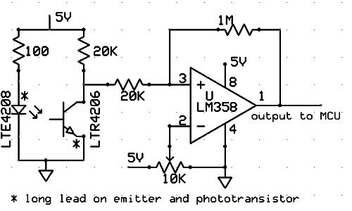
Motion sensing is implemented using IR sensors. The idea to use these was taken from the tachometer in Lab 4 of ECE 4760. Back in Lab 4, we used them to detect when a fan, which had a dab of white paint on it, had completed a rotation. We realized that the same circuit could be adapted to send signals when a human hand is waved in front of it. The same LTE4208 IR emitter and LTR4206 phototransistor can be used in conjunction with an LM358 op amp and a 10kohm trimpot to create a simple short-range motion detector with hysteresis. For our project, we wired two of these according to the same diagram we used in Lab 4 (schematic from ECE 4760 website):
![[IR SENSOR DIAGRAM]](yl478_clt67_files/image008.jpg)
![[Some Pic]](yl478_clt67_files/image010.jpg)
The result was two IR sensors capable of sending motion detection signals to the MCU. The 1M? feedback resistor sets the hysteresis well enough that only one pulse is sent to the MCU on a hand wave, although we also implement a software debouncer as described later. This is good. If the hysteresis were too weak, then the gaps between a visitors fingers would send multiple pulses and we would be sending Next Slide commands far too often. This could result in endangering our project components when the visitor bangs angrily on the box.
IR Sensors operate by detecting bounced infrared light. The LTE4208 IR emitter is the source of the infrared light and bounced light intensity is detected by the LTR4206 phototransistor. The variation in current is put into a comparator (composed of the LM358 and the 10k trimpot), which will raise the signal to the MCU.
The problem with this design is the short range of the sensor. The infrared light is subject to scattering when objects are very far away. Luckily, the lack of range is perfectly okay for our project, as we expect users to wave their hands relatively close to the sensors during usage. The variation in bounced infrared light detected results in a comparator low (active low), which is sent to PINA0 and PINA1 of the MCU.
The two IR sensors are located on top of the box on the visitors left and right hand sides. When the user waves his hand over the sensors, keyboard scan-codes are sent to the host computer as left-arrow and right-arrow key strikes. There are also two pushbuttons that have exactly the same function for people who prefer the tactile feedback of buttons. The USB communication is described in the USB interfacing section later in the report.
Passive Infra-Red (PIR) Sensor
We use a PIR sensor to simply detect the presence of a visitor in the general vicinity of the project.
![[Some Pic]](yl478_clt67_files/image012.jpg)
![[Some Pic]](yl478_clt67_files/image014.jpg)
The PIR sensor is a pyroelectric sensor that detects changes in infrared radiation levels through two slits. When a warm body passes through, one slit detects a higher IR level than the other, and a signal is sent to the MCU. The PIR is set in retriggering mode. The effect of this mode is very similar to hysteresis. When "continuous motion" is detected (a hand waving in front of it), multiple signals could be sent (non-retriggering mode). In retriggering mode, the signal remains high. Despite this mode, we still implement a debounce state machine for more reliable performance.
Upon detection of a signal from the PIR sensor (through PINA4), the MCU initializes a read of an MP3 from a Micro-SD card and passes the data to an MP3 decoder for playback as a greeting to the visitor.
IR Sensor vs PIR Sensor, Range vs Cost
One thing we noticed very quickly was that the PIR sensor had a very large range. With this in mind, we use the PIR sensor for the front, because people may be walking very far away from the display. The IR sensor, on the other hand, does not have the range necessary for this and is thus unsuitable for "person-detecting".
Control sensing is a different story. Unless the visitor has abnormally long arms, the person interacting with our project will likely be standing right in front of the display, and range is no longer as critical. Thus, we need high precision, short range detection for as cheap a cost as possible. We chose the IR circuit because it was much cheaper than the PIR sensors (which are $10 each) and also had the range we required. People following this project can also save some money if they wish to implement it themselves.
MP3 control button
We added a button that lets the user control the MP3 playback. Pressing the button and releasing after less than 2 seconds will pause playback, pressing it again will resume playback. If the button is held down for more than 2 seconds, the device skips to the next audio file, allowing the user to cycle through all the files stored on the SD card.
Software Debouncer and State Machine
Task1 in main.c runs a state machine that checks the sensors and buttons and calls the corresponding functions to control the playback of audio and send the key presses to the computer by USB.
SD Card
We mounted a SD card adapter from Digikey on a solder board.
![[Some Pic]](yl478_clt67_files/image016.jpg)
The relevant pins for the SD card are as follows:
|
Pins |
Description |
|
CS (active low) (PINB4) |
This pin is set low by the MCU whenever data is sent. If it is high, then the data is ignored. |
|
DI (PINB5) |
This is also known as MOSI. This pin is used to send data from the MCU (master) to the SD card (slave). |
|
DO (PINB6) |
This is also known as MISO. This pin is used for the SD card (slave) to send data back to the MCU (master). |
|
SCLK (PINB7) |
This is provided by the MCU. During initialization, this cannot exceed 400kHz, but in normal operation it can be turned up to ½ the MCU crystal frequency when the MCU is master (the MCU is always master in our project). This is done through the SPCR reg. |
|
GND |
This is the MCUs ground connection. |
|
Vin |
The SD card can function in a voltage range of 2.7-3.6V, we supply a voltage of 3.3 V from a voltage regulator. |
The SPI pin choices here are by design for the Mega644. These are the only pins that our MCU uses for SPI protocol.
SPI Protocol
Initialization and communication with the SD card and VS1011E-L are done through the SPI protocol, which is controlled primarily by the SPCR register of the ATMega644. We set the 8-bit SPI control register (SPCR) as the following:
|
SPCR bit |
Description |
|
Bit 7 (set to 0) |
Setting this to 0 disables the ISR. |
|
Bit 6 (set to 1) |
Enables SPI for the MCU. |
|
Bit 5 (set to 0) |
Setting this to 0 indicates that we send data MSB first. |
|
Bit 4 (set to 1) |
This sets the MCU as master. |
|
Bit 3 (set to 0) |
Clock polarity - 0 means that the base value of the clock is zero. |
|
Bit 2 (set to 0) |
Clock phase - Data is captured on the clocks rising edge and data is sent on the falling edge. |
We chose to set the Clock polarity and phase as 00; this combination of (CPOL, CPHA) is called SPI Mode 0.
The final two bits (Bits 1 and 0) set the clock speed.
Setting the clock speed is very important, since the slave devices (SD card and VS1011E-L) can only handle certain operations below a certain speed.
SPI Clock Speed
The speed of the SPI clk must be slow (below 400kHz) for certain operations like writing data or initializing the SD card. The clk speed is given by bits 1 and 0 of the SPCR register and by a bit in SPSR called the SPI2X bit. This bit doubles the clock rate. The following are the settings we use (with a 16MHz MCU crystal):
|
Speed |
SPCR bit 1 |
SPCR bit 0 |
SPSR SPI2X bit |
|
125kHz |
1 |
1 |
0 |
|
2MHz |
0 |
1 |
1 |
|
4MHz |
0 |
0 |
0 |
The 125kHz speed is used to satisfy the 400kHz upper limit during initialization of the SD card and other purposes. The 2MHz is used to communicate with the VS1011E-L later on (the max speed it can write with is 4MHz). The 4MHz is the normal fast mode.
SD Card initialization
The SPI bus consists of four main wires: SCLK, DI (MOSI), DO (MISO), CS (chip select). In our project, the MCU is the master at all times. The SD card is always the slave.
The SD card must first be initialized before it can be used. This must be done at a frequency below 400kHz. Afterwards, the clock speed may be turned up to our normal 4MHz. CS must be held low (active low) during data sending. If CS is not low, the sent data is ignored.
Experiences with implementing the SD card access
While we were developing the project, the controller suddenly stopped being able to read the SD card. After a few days of being unable to get it to work, we discovered that the card had become corrupted (perhaps from bad commands sent over the SPI bus when we have errors in our code) and FatFs could not read it as it did not implement CRC error correction (the card could still be read in windows). Formatting the card solved the problem. We are reporting this experience because it might save future groups some frustration if they encounter such problems.
Having two devices share the same SPI bus was also a challenging part of our project. We spent many days getting the right order in which to start up the MP3 decoder and SD card as well as flipping their CS bits in order to coordinate their communication with the microcontroller such that only one device is transmitting at a time.
FatFs System
We formatted our SD card with FAT16 format. We chose to use Elm-chans module to help us read and write with it. FatFs is a FAT file system library that allows microcontrollers to open and close files, read and write to them, open and read and make directories, and many other file system operations. The FatFs functions we used can be identified readily by the f_ prefix to the function name (e.g. f_open to open a file). For the physical layer interface code, we use the diskio.c file provided by here.
USB Interface
USB cables have four connections: Vcc, Gnd, D+, and D-. The Vcc is 5V with respect to the given Gnd, and the data on the D+ and D- connections are sent and received in the range of 2.7V to 3.6V.
Communication with the PC using V-USB is done by sending the scan-codes for the Left-arrow and Right-arrow keys on a USB keyboard through D+ and D-. The code for Left-arrow is 0x50, and the code for Right-arrow is 0x4F. Before being able to send these codes, however, the MCU must be recognized as a USB HID Keyboard device by the computer. This is accomplished by sending the appropriate USB descriptor after plugging into the computers USB port.
The following USB report descriptor has descriptions next to it:
PROGMEM char usbHidReportDescriptor[USB_CFG_HID_REPORT_DESCRIPTOR_LENGTH] = {
    /* USB report descriptor */
    0x05, 0x01,    // USAGE_PAGE (Generic Desktop)
    0x09, 0x06,    // USAGE (Keyboard)
    0xa1, 0x01,    // COLLECTION (Application)
    0x05, 0x07,    //   USAGE_PAGE (Keyboard)
    0x19, 0xe0,    //   USAGE_MINIMUM (Keyboard LeftControl)
    0x29, 0xe7,    //   USAGE_MAXIMUM (Keyboard Right GUI)
    0x15, 0x00,    //   LOGICAL_MINIMUM (0)
    0x25, 0x01,	   //LOGICAL_MAXIMUM (1)
    0x75, 0x01,    //   REPORT_SIZE (1)
    0x95, 0x08,    //   REPORT_COUNT (8)
    0x81, 0x02,    //   INPUT (Data,Var,Abs)
    0x95, 0x01,    //   REPORT_COUNT (1)
    0x75, 0x08,    //   REPORT_SIZE (8)
    0x25, 0x65,    //   LOGICAL_MAXIMUM (101)
    0x19, 0x00,    //   USAGE_MINIMUM (Reserved (no event indicated))
    0x29, 0x65,    //   USAGE_MAXIMUM (Keyboard Application)
    0x81, 0x00,    //   INPUT (Data,Ary,Abs)
    0xc0           // END_COLLECTION
};
Because the drivers for USB Keyboard recognition are on nearly all computers by default, our project requires no drivers of its own, allowing for easy "installation" and use.
At boot-up, we software-disconnect the USB interface for 500ms after building the first USB report and init. We then reconnect it and simulate "plugging the USB in".
We built a circuit for connecting the microcontroller to the USB socket and performing level conversion as specified at V-USB. Since our Mega644 has an output high level of 5 V while the D+ and D- USB inputs need to be 3.3 V, we use zener diodes to drop the voltage from the Mega644 down to 3.3 V. Later on we discovered that this voltage shifting can also be done using the Texas Instruments TXB0104, which might be a better solution due to its higher precision in shifting the voltages.
![[Some Pic]](yl478_clt67_files/image018.jpg)
Audio Playback
Audio playback is done by first reading MP3 data from the SD Card and then sending it to the MP3 decoder. We explored using two different MP3 decoders.
VS1011E-L MP3 Decoder
![[Some Pic]](yl478_clt67_files/image020.jpg)
The VS1011E-L (http://www.vlsi.fi/uploads/media/vs1011_01.pdf) which was mounted on a breakout board from Sparkfun (http://www.sparkfun.com/products/8126) uses an SPI interfaces, to receive commands and data. Besides the MOSI, MISO pins, we also connect the following pins to Port B on our microcontroller as shown in the following table.
|
Pins |
Description |
|
Vcc and Gnd |
3.3V connection and MCU ground |
|
SCLK (PINB7) |
Same as for the SD card. |
|
CS (active low) (PINB3) |
This is Chip Select for the command bus. |
|
DCS / BSYNC (active low) (PINB2) |
This is the Chip Select for the data bus. BSYNC is the other purpose (and main name) of this pin used in VS1001 compatibility mode. We operate in VS1002 native mode, in which the pin functions as a chip select (DCS). |
|
RST (PINB1) |
This is effectively a Power-down signal. The VS1011E-L goes into a super low power state and the internal frequency and mode registers are wiped and need to be re-set. |
|
DREQ (PINB0) |
This pin is the VS1011E-L's output when it wants to request more data. It is effectively a ready signal. When it is low, the MCU stops sending data. When it is high, the MCU sends data if it can. |
Use of these pins will be described shortly. Our code for interfacing with the VS1011E-L is based on the VS1033 code at http://www.instructables.com/id/Music-Playing-Alarm-Clock/, with modifications to allow for playback while simultaneously running our motion detection and USB tasks, as well as to differences in the instructions written to the decoders registers due to differences between models and our desired functions.
The VS1011E-L also has three important registers that must be set after boot-up. We set the following during the VS1011E-L's initialization function:
|
Register |
Description |
|
SCI_MODE |
Setting this Mode Register to 0x0802 enables VS1002 Native mode (allows us to use BSYNC as a chip select DCS) and allows MPEG Layers I & II. |
|
SCI_CLOCKF |
Setting this to 0x9800 gives us a 12.288MHz internal clock. |
|
SCI_VOL |
Setting this to 0 gives us maximum volume. The value of this register really means attenuation (0 attenuation). |
There are several timing restrictions we must respect when interfacing with this device. We cover these restrictions while also covering some details on common operations with the VS1011E-L below:
Initialization
Initialization consists of waking the device from reset mode (outputting 1 to RST) and then writing the Mode, Clock, and Volume Registers as described above. This requires register writes, which are conducted according to the process described just below here.
During Register Writes
Register writes must be done below ¼ the external clock speed. This means we cannot use our 4MHz main MCU clock, since it brushes the allowed maximum. We use the 2MHz clock instead (we set the SPCR and SPSR regs as specified earlier).
After asserting the device's chip select, a byte (0x02) is sent to identify the command as a write. The address byte is sent next. Then the data is sent with the most significant byte first. The total data sent is 2 bytes. Afterwards, we deassert the chip select and wait for a ready signal (DREQ high).
Playing an MP3 file
We play our MP3 files interleaved with polls to the sensors, allowing us to respond to user interaction while playing an MP3 even though we are single threaded.
We play 32 bytes of MP3 data at a time. DCS is asserted and deasserted in the normal manner for this process. Note that the SPI clock must be limited to send data as in all the above cases. The 2MHz clock is used during data sending.
STA013 MP3 Decoder
![[Some Pic]](yl478_clt67_files/image022.jpg)
![[Some Pic]](yl478_clt67_files/image024.jpg)
We also tried using an STA013 decoder. We wrote code for it as well, but because its success rate was rather unreliable, we switched fully to using the VS1011E-L instead. We based our construction of the STA013s circuits and code on the guide at here.
The STA013 requires I2C communication with the microcontroller in order to send a configuration file and the board parameters to the STA013. Although a few ECE 4760 projects in previous years have made use of the STA013, they used bitbanging (toggling ports high and low with delays in between) to simulate I2C communication instead of using the Two Wire Interface (TWI) that is integrated into the Mega644.
We decided to part with the tradition and switch to using the TWI bus of the the Mega644. At first we tried to use a sample library provided by Atmel (Src) but could not get it to work. We ended up writing our own routines to use the TWI based on what we read from the Mega644 datasheet and the guides at here and here.
Using our TWI code, we were able to send communicate with the STA013 successfully. We could try to read from address 0x01 on the STA013 and it would correctly reply with a response of 0xAC. We were also able to send the configuration file to the STA013 (converted from here and stored in STA013_config_file.c) and instruct the STA013 to start and play. However, the I2C transmissions randomly fail and often the STA013 would not assert a request for data (which is the signal that it playing). We are providing our code as it may be useful for future groups that want to use the TWI bus on the Mega644.
Power Circuitry and Voltage Shifting
![[Some Pic]](yl478_clt67_files/image026.jpg)
As the VS1011E-L, STA013 and SD card all run on 3.3 V voltages, we used the Texas Instruments LP2950-33 voltage regulator (here) to create a 3.3 V power supply. A tricky part of this project was that due to the V-USB code being unable to function at 8 MHz, we could not simply run the Mega644 at 3.3 V with a 8 Mhz crystal. As a result, we ran the Mega644 and sensors at 5 V using a 16 MHz crystal. The circuit for the 3.3 V supply was built on the same board as the SD card adapter to save space, as shown above.
The connections between the Mega644 and the components running at 3.3 V then had to be voltage shifted. We managed to find an IC that could perform bidirectional voltage shifting from 3.3 V to 5 V in the form of the Texas Instruments TXB0108 (here). The TXB0108 can shift 8 bits of input, which was exactly the total number of connections that the Mega644 had to the VS1011E-L and the SD card. The TXB0108 we used is shown in the photo below.
![[Some Pic]](yl478_clt67_files/image028.jpg)
The TXB0108 performed well and we think that it is worth considering by future ECE 4760 groups that need to do voltage shifting in their projects. A 4 bit version is also available in the form of the TXB0104.
Enclosure and assembly
![[Some Pic]](yl478_clt67_files/image030.jpg)
![[Some Pic]](yl478_clt67_files/image032.jpg)
![[Some Pic]](yl478_clt67_files/image034.jpg)
![[Some Pic]](yl478_clt67_files/image036.jpg)
Changes from Original Design
In the original design from our proposal, we used PIR sensors for all of our motion sensing. Range and cost considerations led us to switch to IR sensors for control, and we kept one PIR sensor to detect people in the area. We also decided on using VS1011E-L MP3 decoder instead of the STA013 as it performed more reliably.
Results
[Top]Motion Detection
The device was able to correctly detect an approaching person using the PIR sensor and a persons hand motions using the top mounted IR sensors. The range of the PIR sensor was sufficiently long, it could detect a person up to a meter or two away, which is a good approximation for the maximum range that people would view the display from. The top mounted IR sensors could detect a hand up to 5 cm away, which is sufficient. The sensitivity of the IR sensors can be adjusted using the trimpot.
Control
The device was able to connect to the several computers that we tested it on and be recognized as a generic Human Interface Device. Sometimes, however, the computer did not recognize the device, but re-plugging it in usually fixed this. Pressing the buttons or activating the IR sensors resulted in the appropriate keystrokes being transmitted to the computer.
MP3 Playback
We loaded various MP3 files of different bit rates on the SD card and played them. The device successfully played most of the files. However, for MP3 files encoded with a high bit rate (such as greater than 192 kbps), some stuttering occurred occasionally as the data could not be supplied to the MP3 decoder fast enough due to processing time being used for other tasks such as sending the USB reports and checking the sensors.
Useability
The device is easy to use. The debouncing for the buttons and sensors worked correctly. To control the PowerPoint display and audio playback, the user simply needs to press buttons or wave his hand over the sensors.
Conclusions
We were able to meet all the goals that we set in the proposal. The controller is able to perform the functions of controlling the display and playing MP3 files from an SD card that we proposed.
Things that we would do differently next time include using a TXB0104 voltage shifter to shift the voltages for the D+ and D- of the USB connection instead of zener diodes, since the TXB0104 is more precise in the voltages it produces, while using the diodes required some trial and error to find the model that dropped that right voltage.
We could also try powering the entire device off the USB bus, thus eliminating the need for a power adapter. If we upgrade from the VS1011E-L to the VS1053, which supports audio encoding, we could add a microphone that users can speak into to leave feedback and suggestions. The recordings will be encoded by the VS1053 and stored on the SD card.
Intellectual Property
The idea for this project is attributed entirely to Professor Bruce Land, teaching ECE 4760. However, the design and implementation of this project is our work. We used code that is distributed under the GNU General Public License for communication with the SD card and from V-USB to interface with the host computer, and we take no credit for these parts (labeled in the code). There are probably no patent or publishing opportunities for this project. This is a fun project that can be used for convenience by public PowerPoint display administrators. With respect to PowerPoint, we do not own or take any credit for the software. All of that belongs to Microsoft. Our project is only meant to streamline the interface between users and the PowerPoint slides.
Ethical Considerations
In this project, we have tried our best to conform to the IEEE Code of Ethics. We made design choices with safety in mind, and we have enclosed all potentially dangerous parts of the design in a non-conducting container. The apertures for the IR/PIR sensors are not large and pose minimal risk to users. The IR emitter poses a potential risk to the human eye if it is stared at directly, but this is only the case for large numbers of IR diodes at once. Because the human eye pupil does not respond to IR rays, the retina can get damaged if a large number of IR rays are stared into (Src). However, a single one or two do not pose a significant risk, although users should still try not to stare into them.
We have been helpful to other groups and people where possible, giving advice if asked and input if requested. One group requested our help with their SD card, and because we had ours working, we helped them interface with theirs, explaining what sites were helpful to us when we were setting ours up. Also, Texas Instruments was kind enough to donate some good voltage regulators and voltage shifters for our project.
During help, if we were uncertain of our technical competence, we gave appropriate warning. Our advice to others and our data in this project have all been honest and realistic, and we sought criticism from other groups in times of uncertainty. The atmosphere in this class has always been friendly, and there has been no cut-throat mood at all. Everyone can offer and receive criticism, and errors are corrected for the good of all. For us, this has remained true regardless of the circumstances around the requesting individual (race, gender, etc.). We avoided injuring others in our lab hours, keeping all dangerous wires well out of the way of potential bystanders. We shunned the possibility of bribery.
Our project is a small contribution to the worlds understanding of technology, but hopefully the documentation of its implementation here will be helpful to others attempting similar designs. We encourage others to adhere to the IEEE code of ethics to foster the helpful community of engineers that every nation needs.
Standards
The standards and formats involved in the project are Secure Digital, MP3 format, SPI protocol, I2C protocol, USB 1.1.
Societal Impact and Possible Improvements
Our device will not likely have any societal impact. It is a fun device though. We could possibly improve this aesthetically. The USB recognition is not entirely stable and could be fixed to be more stable. We could also implement wireless communication to allow it to interface with the host computer from farther away.
Appendix A: Photos
[Top]
FILES
Appendix B: Code
[Top]main.c
mp3_STA013.c
mp3_VS1011E.c
SDcard_audio.c
Rest of Code Directory
Appendix C: Schematics
[Top]![[Some Pic]](yl478_clt67_files/schematics.bmp)
Appendix D: Cost Details
[Top]|
Part |
Source |
Unit Price |
Quantity |
Total Price |
|
ATmega644 |
Lab |
$8.00 |
1 |
$8.00 |
|
PCB for ATmega644 |
Lab |
$4.00 |
1 |
$4.00 |
|
12V Power Supply |
Owned |
$0.00 |
1 |
$0.00 |
|
Passive Infra-Red Sensor |
Adafruit |
$10.00 |
1 |
$10.00 |
|
SD card adapter |
Digikey |
$2.67 |
1 |
$2.67 |
|
VS1011E-L breakout board |
Sparkfun |
$19.95 |
1 |
$19.95 |
|
3.5mm audio jack |
Digikey |
$1.41 |
1 |
$1.41 |
|
LP2950-33 3.3V voltage regulator |
Texas Instruments |
Sample |
1 |
$0.00 |
|
TXB0108 |
Texas Instruments |
Sample |
1 |
$0.00 |
|
DIP socket |
Lab |
$0.50 |
1 |
$0.50 |
|
USB socket type B |
Lab |
$0.00 |
1 |
$0.00 |
|
USB cable |
Owned |
$0.00 |
1 |
$0.00 |
|
Push Buttons |
Lab |
$0.00 |
3 |
$0.00 |
|
Solder Board |
Lab |
$2.50 |
1 |
$2.50 |
|
Small Solder Board |
Lab |
$1.00 |
1 |
$1.00 |
|
SIP/Header pins and sockets |
Lab |
$0.05 |
95 |
$4.75 |
|
SOIC carriers |
Lab |
$1.00 |
2 |
$2.00 |
|
Enclosure |
Salvage |
$0.00 |
1 |
$0.00 |
|
1 Pin Jumper cables |
Lab |
$1.00 |
6 |
$1.00 |
|
IR sensor circuits recycled from Lab 4 |
Lab |
$0.00 |
1 |
$0.00 |
|
Zener Diodes 3.6 V |
Digikey |
$0.54 |
2 |
$1.08 |
|
Total |
$57.78 |
|||
Appendix E: Task Breakdown
[Top]|
Task |
Contributor |
|
High level design |
Both |
|
Drawing schematics |
Chris |
|
Sourcing components |
Yi Heng |
|
Sensors and buttons |
Both |
|
SD card |
Yi Heng |
|
VS1011E-L MP3 decoder |
Chris |
|
STA013 |
Yi Heng |
|
USB communication |
Both |
|
Power circuitry and voltage shifting |
Yi Heng |
|
Soldering |
Both |
|
Dremeling |
Both |
|
Status Reports to TA |
Chris |
|
Webpage and documentation |
Both |
References Used
[Top]LTE4208 IR emitter
LTR4206 phototransistor
LM358 op amp
SPI SPCR Register Information
V-USB
USB Keyboard Scan Codes (Page 55)
STA013 MP3 decoder
STA013
I2C
I2C
TUSB1106 USB transceiver
Music Playing Alarm Clock
SPI Protocol
FatFs
LED safety
VS1011E-L datasheet
Acknowledgements
[Top]We would like to thank the following people and organizations for their help with our project
- Bruce Land for providing the idea for this project and his technical advice over the semester.
- Our TA Jeff Yates for the assistance he has provided over the semester.
- Texas Instruments for providing us with sample ICs
- Spring 2011 Yi Heng Lee, Chris Torng -