
SensCap is a device that guides the visually impaired around obstacles.
Introduction
We designed and built a device to be worn on the head and around the hip to aid the visually impaired maneuver around obstacles. It provides information about obstacles near and around the head. When used with a cane, the user will have a complete sense of the topology of surrounding environment. Our device decreases the dependence of the visually impaired on others and increases their safety.
Our device uses two ultrasonic sensors and a microcontroller to determine the proximity of the user to obstacles. The user has the option to choose between two modes of user feedback-headphones or vibrating motors. Both provide information about the location of and distance to an obstacle. The harder the motors vibrate or the louder the sound is, the closer the user is to an obstacle.
High Level
Rationale
The purpose of this project is to aid the visually impaired with everyday tasks by providing more information to them about their surroundings. Typically, a person with no or poor vision will use a cane while walking to determine the general topography of the area. A cane is useful for stairs, chairs, and obstacles on or near the ground. The cane has its limitations, however, to objects outside of its radius and off the ground.
A guide dog is also another option for guide while walking. They are unlike canes in that they can interact with humans by find a clear path for walking, an empty park bench, or bus station. However, they cannot be brought everywhere and are not always able to protect the user from obstacles near the head.
We designed and developed a device that will give more freedom in navigation to the visually impaired. Our device is composed of two sonar ranging sensors subtly placed on a baseball cap. The two sensors in conjunction with a microcontroller can provide a plethora of information regarding the surroundings near the head and up to a distance of 5 meters ahead. If used with a cane or guide dog, then one can be fully informed about all potential obstacles at any angle.
The two sensors placed at different angles provide stereo information on obstacles in front of the user. This means when approaching an object, the user would know which way to turn to avoid the object. An ATMEGA644 microcontroller serves as an intermediary between the sensors and outputs. Outputs are in the form of either headphones or two vibrators, both of which can provide stereo information to the user. Switches allow the user to choose the two output forms, turn the device on and off, and to wake the sensor up from sleep mode.
Background Math
The two sensors use sonar. We can calculate the distance from the person to the closest obstacle through calculating the distance sound would travel in the time it took for the sensor to send and receive its sonar signal. The speed of sound is 340 m/s. The sound wave has to travel from the sensor to the object and back. This means distance = 340 * time_elapsed/2. For example, the maximum time of propagation allowed in our circuit is 32 ms, which allows for a sensing distance of 5.44 m ahead.
Logical Structure
Our project can be divided into four main parts: the user control, sensor control, sensor interpretation, and the output to the user. The user control includes the switches that allow the user to choose SensCap's mode of operation. The sensor control determines when to tell the sensor to take a measurement. The sensor interpretation receives the output from the sensor and normalizes it to control value for the sensors. The output to the user composes of sending signals to the earphones and vibrators correctly and have them correctly interpret the signals.
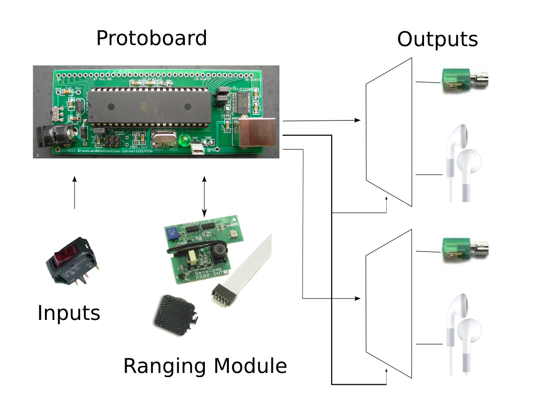
(Click to Enlarge) Figure 1. A high level diagram of our device.
Program/Hardware Tradeoffs
Whether a part of our project is controlled by program or hardware depended mostly on the capabilities of the ATMEGA644 microcontroller and on the accuracy of the design. Many parts of our hardware could have been implemented by the software as well. For example, the microcontroller outputs two built-in PWM functions out of two port pins. We could have made a software version of the PWM function, which would make it unnecessary to have a multiplexer IC chip. However, this may make the circuit inaccurate because the PWM function, especially for the headphones, require very accurate timing, that can only be achieved with hardware. This required us to output PWM for both the headphone and vibrator from the same pin and send them to their respective parts through additional hardware.
However, some parts of our project had to be hardware. For example, because of the large inductive spikes caused by motors like the vibrator, we had to optoisolate our microcontroller from the vibrator to prevent the spikes to blow out pins. Since this serves as the express purpose of protecting our program, this had to be hardware.
Standards
In Multisensor Strategies to Assist Blind People: A Clear-Path Indicator (See References), the author defined criteria for the design of devices used in the assistance of blind people. For clear-path indicators, which our device falls under, the important sensory functions must agree with the degree and redundancy suggested by medical scientists and engineers, and must be versatile to accomodate individual differences, skill, and abilities. In addition, there must be measurement of the device's performance in simplicy of use, users' ability in avoiding obstacles, and specific satisfaction resulting from cost, efficiency, and reliability. How well we met these standards are detailed below.
Hardware Design
Microcontroller
We used a custom targetboard designed for the ATMEGA 644 microcontroller by Bruce and Chun. We used several of the microcontroller's functionalities. We used all three timers--0 and 2 for the pulse width modulation of the output to the user, and 1 for the input capture for interpreting the sensor results. The PWM mode outputs a digital signal that when passed through a low pass filter averages to an analog signal. This was useful to output voltages other than VDD and GND to our outputs, such as that in a sinusoid for the headphones. The MCU had a clock of 16M Hz.
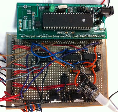
(Click to Enlarge) Our final, soldered circuit with ATMEGA644 on the targetboard.
SENSOR CONTROL
Sensor
Our circuit uses two SensComp 6500 each with its own SensComp 7000 Transducer for transmitting and receiving. The SensComp 6500 is controlled by an initialization (INIT) signal which is sent from the microcontroller. When a SensComp 6500 receives an INIT, it transmits 16 pulses using the transducer and receives the pulses that have bounced off of objects. This sets off our ECHO signal. The time between the INIT signal going high and the ECHO signal going high is the time it took to travel from the sensor to the nearest object within 17 degrees from straight ahead.
According to their datasheet, the sensors have a beam angle of 17 degrees. The angle between the sensors depend on the size of the wearer's head. We aimed to have about 10 degrees of overlapping, so that if an object is directly ahead of the user, both left and right would vibrate and play sounds. Stereo is achieved in the additional 7 degrees on the left and the 7 degrees on the right.
We interspersed the INIT signals from the two SensComp 6500 to avoid cross-talk. One device is on while the other is off. Each sensor outputs a signal at 638 ms, so the left and right outputs at every 319 ms.
SENSOR INTERPRETATION
Trigger
To measure the time that it took for the sensors' signals to travel from transducer to object and back, we used Timer1's capture mode. We have two Senscomp 6500 devices, so they had to share the same D.6 capture pin. Since one is on while the other is off, and thus mutually exclusive, we can simply use an OR gate between the two ECHO signals. For the OR gate, we used the MM74C32N, a Quad 2-Input OR Gate IC chip. In our program, we decode this OR gate by remembering whether the left or right sensor last outputted, so the newly captured value would be associated the sensor that was used. One of these values would be associated with the left earpiece and left vibrator, while the other would be associated with the right earpiece and right vibrator.
OUTPUT TO USER
Headphones
We used a set of headphones. The headphones are set up using simple low pass RC filters. The varying voltages of the sine waves are output using pulse width modulation (PWM). We had to average over these PWM's with low pass filters. We used a PWM time period of 15us, for a frequency of 67 kHz. We used an RC filter of 50kOhms and 10nF, for a time constant of 500us, averaging over enough of the PWM to smooth it over.
Vibration
We used vibrating mini-motors for the vibration feedback mechanism. The more voltage applied, the stronger the device vibrates. Because the vibrators are mini motors, they must be optoisolated from our microcontroller so that their large inductance spikes will not destroy our port pins. We used the 4N35 phototransistor for this purpose.
When we originally hooked up a voltage from the optoisolator to the vibrator, we found it did not run. We believe this is because the voltage was not driven strong enough by the optoisolator so the vibrator brings it down to zero. We fixed this by modeling our circuit after Lab 4, where we added in a BUZ73 to drive the motor.
Because the motor vibrates by itself, without needing the varying voltages that headphones do, we did not need to use a sineTable lookup table. We output a constant to the motors using PWM. Because the vibrator needs to use an optoisolator, we had to decrease our PWM time period to 7.5 ms, for a frequency of 133.3 Hz. The vibrator motor is a lowpass filter itself, so we did not need to add the RC filter as we did for the headphone.
We originally placed the mini motors on the inside of the hat for subtlety, but the motors were too sensitive to touch. They stopped moving with even the slightest adjustment in hat position. We then placed them on the hat, and it worked better, but with some problems documented below.
Switch Between
The headphone and vibration modes both use the same PWM ports, but are driven by different PWM modes and frequencies. We let the user switch between the two. We used MC14066BCPG, Quad Analog Switch/Quad Multiplexer IC chips so that the headphones would not be driven in vibration mode and vice versa. We output outputMode and its complement to choose whether the two PWM signals would go to the headphones or the vibrators.
We had a lot of difficulty with this simple chip. Both vibrator and headphones were on even though only one was supposed to be on. One would turn off when we start probing the IC chip to see what was wrong. We realized the problem was that the outputMode was not being driven effectively to ground by itself. We assisted it by adding in a pull-down resistor of 1M Ohm to help it settle down to zero. This let our multiplexer effectively turn off one of the outputs.
Another problem we ran into was that in vibrator mode, small spikes of voltage still seeps through to the headphones, resulting in audible clicks every time the sensor sends out pulses. Since the sensors take measurements every 319 ms, the frequency of these clicks are roughly 3 Hz. We realized we can just high pass filter it out in vibration mode without affecting the higher frequencies in headphone mode. We used a simple RC high pass filter of 0.1uF and 5.1kOhms, which removed the clicking noise effectively.
USER CONTROL
Switches
The user controls SensCap operation with three rocker switches. One of the switches turns the microcontroller on. Another switch turns the sensors on. In order to have the SensCap fully functioning, both of these switches must be turned on. Our third switch allowes the user to switch between the headphone and vibrating modes. The switches that we found in the ECE 4760 lab and bought are on-off switches which allow for switching between open and short circuits. This was a problem since we needed the switches to switch from Vdd to ground. We solved this problem by attaching a 50K Ohm pull up resistor. When the switch is in its open circuit state, the output voltage will go to Vdd. When the switch is in its short circuit state, its resistance is much smaller than 50k Ohms. By voltage division, the output voltage drops to Gnd.
Portability
In order for this device to be easy to use and practical for the visually impaired, we had to carefully design the wearable components of this device. We chose to use a baseball cap as opposed to any other kind of hat because it is easy to instruct how the hat should be worn. The brim of the cap should be worn facing forward. This is important because the sensors are fixed to the cap and must face the correct direction in order to operate in a helpful manner. In addition, many people wear baseball caps, so the SensCap would not stand out.
Next, we chose to use a hip pack in order to allow this device to be "hands free." The user will probably be using one hand to use a cane and it is important not to impede the user's motion. The hip pack has switches on the side that should be facing forward. Each switch has a raised dot on it to indicate the "on" position and vibration mode. In the hip-pack, the circuitry is completely separated in its own zippered compartment from any area that the user touches. Also, there is a separate component for storing all of the batteries. This is to keep anyone using this device from touching the actual circuit.
To be completely portable, we powered our device with batteries. The microcontroller was powered by a 9V battery, while the rest of the circuit was powered by 4 AA 1.5V batteries. While the microcontroller worked immediately, the rest of our circuit did not operate with the 6V provided by the 4 AA batteries. We believe this was because we were close to the maximum voltage allowed for the sensors, and thus weren't operating correctly. We fixed this problem by adding in a diode between the VDD of the battery pack and VDD of the circuit. This effectively dropped the VDD voltage down to 5V, which let our circuit work correctly.
There is a headphone jack which allows flexibility with the type of headphones used. Using a headphone jack is also good for our debugging since we can plug in speakers. Both of us can listen to the sounds at the same time. Because this device is designed for the visually impaired, there is a raised dot on the right-ear-earpiece to indicate to the user which earpiece should go in which ear. This is important because the right-hand-side earpiece corresponds to the right side of the body and the sensor on the right-hand-side. The left-hand-side earpiece corresponds to the left side of the body and to the sensor on the left-hnad-side.
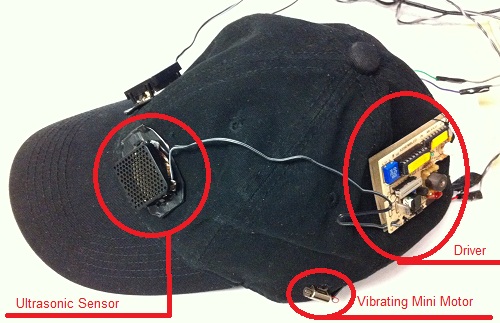
(Click to Enlarge) Profile of our baseball cap with an ultrasonic sensor, vibrating mini motor, and driver circuit. There is an identical circuit on the other side of the hat.
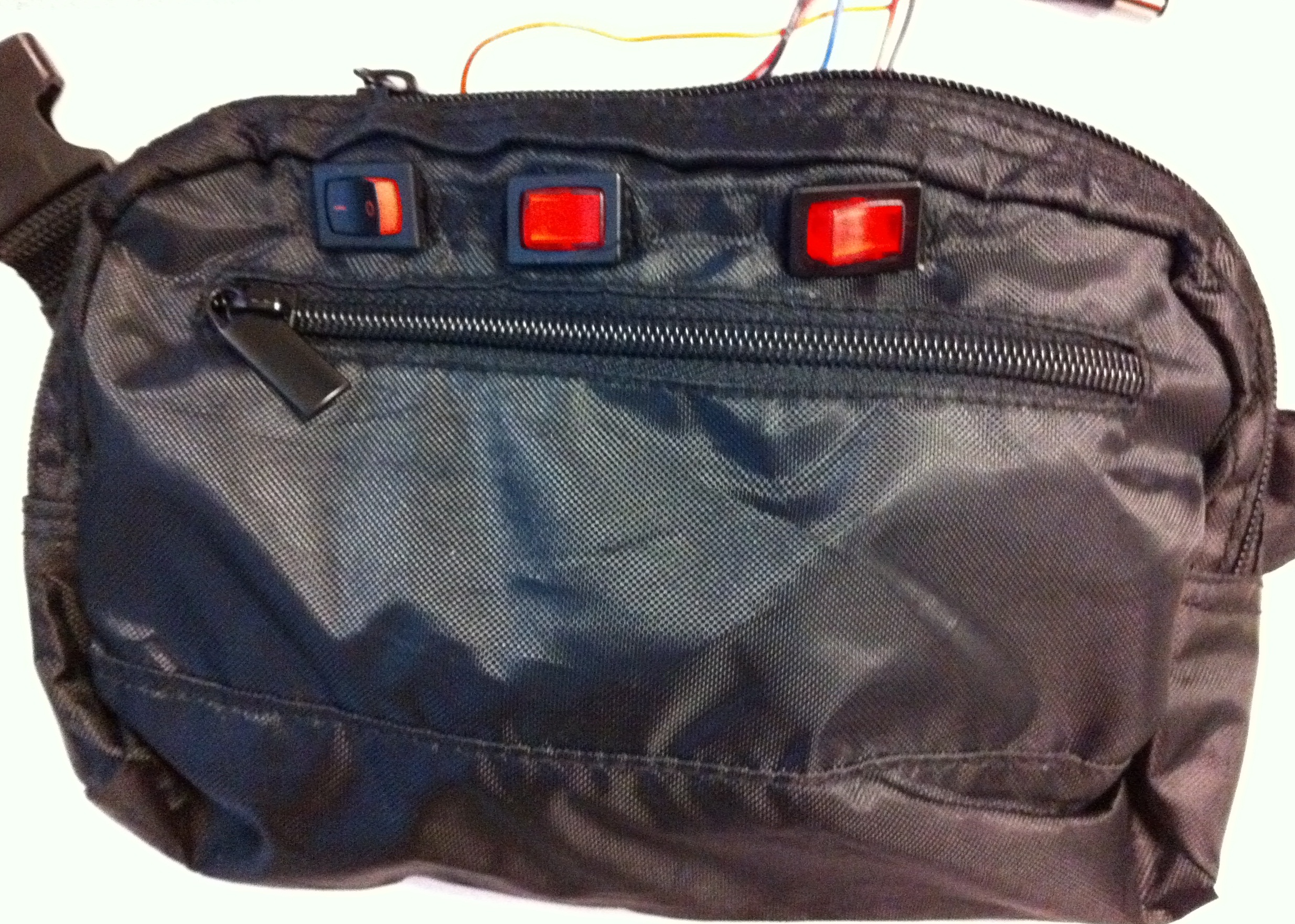
(Click to Enlarge) Our hip-pack with three switches.
Software Design
USER CONTROL
All of user control was done through hardware.
SENSOR CONTROL
The sensors only require the microcontroller to send an INIT signal, receive the ECHO signal, and calculate the difference in time. To avoid crosstalk between the sensors, we interspersed the INIT's using a state machine. The state machine in task1 consists of states of the four combinations of middleNullTime and sensorsTakeTurns. The two sensors alternately output every other time task1 is run. For example, the left sensor would output, then null time, then right sensor, then null time, and so on, where each step is 319 ms.
SENSOR INTERPRETATION
It is important to realize that the equation presented in the Background Math section is incomplete. This is because it takes time for the INIT signal to reach the sensor, to charge the transducer, and for the ECHO signal to reach the microcontroller. We find that if we are right in front of the transducer, the time measured is 2.6 ms. This is an offset to our echo signal that has to be subtracted from the measured time, before calculating the distance.
We used a timer 1 with a prescalar of 1024. This allowed us a resolution of 64 us, which corresponds to a 0.011m in distance. To throw away the larger distances and to facillitate the translation to voltage outputted to the headphone and vibrators, we set a ceiling of 32 ms, which corresponds to 4.98 meters away. Anything over the ceiling would be considered to be 4.98 meters away.
OUTPUT TO USER
Headphones
For the headphones, we used timer 0 and 2's PWM function. Because the sinusoids change quickly, we had to choose the small prescaler of 1. The programming aspect of creating the sinusoid uses the overflow property of the int variable, 'accumulator', to cycle through a sineTable. A specific frequency is represented by its corresponding increment. A larger 'increment' represents a higher frequency because it cycles through the sineTable faster. We achieved better frequency resolution by using a 16 bit accumulator and shifting it to an 8-bit highbyte, before reading from the sineTable.
We varied the frequency and loudness of the sound according to the distance measured, where loud and high means closer, and soft and low means further. This was easy to differentiate, and thus became our final design. We implemented this by increasing the increment and shifting the voltage to the right, because shifts are divisions by multiples of 2.
We normalized the frequencies, so that at a maximum of 5.44m, the frequency is at very low bass frequencies and the loudness shift is at 5, which is very close to inaudible. At the minimum distance of 0, the frequency is normalized to 1500V and loudness shift at 0, which is loud and high like a scream to catch the user's attention. This is never reached, however, because of the floor of 2.6 ms. This means the highest frequency and loudness shift are at 1377 Hz and 0. Because there are only integer values of shift, we divided up the softShift into bins, where a distance of 0 m to 0.646 m is categorized as no shift of 0 dB drop, a distance of 0.646 m to 1.734 m is categorized as a 1 shift of 3 dB drop, a distance of 1.734 to 2.822 m is categorized as a 2 shift of 6 dB, and so on. The frequency was simply controlled with the increment added to the accumulator, where a higher increment means closer distance and a lower increment means farther distance. The resolution of frequency is much finer than that of the loudness shift, where the finest sensor resolution of 0.011 m corresponds with a resolution of 3 Hz. This means the drop in frequency per meter out is 272 Hz.
Vibrating Mini Motors
For the headphones, we had a prescaler of 1, but for the vibrator, we set the prescaler to 64. This is because while the fast changes of audible sinusoids in 'steady state' require a fast clock and low prescaler, the vibrator voltage does not change in 'steady state', so the PWM function describing it does not have to change quickly. Another reason is that the optoisolators have a low passing frequency threshold so it requires a slow PWM frequency, so we used a larger prescaler of 64. The vibration code was simple, as neither a sineTable nor an accumulator was necessary.
However, one of the problems we had was that the vibrator's leads are small and weak, so when we apply too much voltage across it, it would vibrate too much and break the leads. In addition, if it vibrates too much, it may be uncomfortable for the user. We limited the vibrator's output by outputting only if the output voltage would be less than 50/255*5V = 0.98V.
Other Things We Tried
The most difficulty we had was representing the distance using the headphones. We tried multiple methods of representing distance with sound. First, we tried to represent distance using the frequency of the output sinusoid where higher frequency meant closer. This was simply done by changing the increment variable. When we tested this, it was very difficult to differentiate which ear was hearing which frequency and whether a frequency was high or not.
Since pitch was difficult to differentiate, we tried varying the times between beeps, where longer intermediate times meant longer distances. This did not require differentiating between frequencies, so should be easier to understand and use. We implemented this by varying the wait times between ramp up and the next ramp up. However, we found this was difficult to use as well because when both earpieces were beeping, it was difficult to keep track of which beeped faster. We ended up varying the frequency and the loudness. This is much easier to use than the above two methods. It is easier to understand which sound each earpiece is receiving.
We had some trouble with the vibrators as well. They were difficult to feel when vibrating on the cap. When we tie it more tightly onto the cap, then the vibrator would choke and no longer vibrate. We ended up tying it loosely so that it would reliably rotate. The problem, though, was that it became difficult to tell the difference in vibrations, especially for people with thick hair. However, differences between very close and very far are easy to feel, so it works for the extremes, but not for finer resolutions.
Design Results
Our device works as expected as can be seen by the screenshots below. Below, we have images taken from an oscilloscope of the sine waves that are sent to the headphones. We have three different images of data taken at three different distances. The frequency and amplitude of the sound increase as the distance to an obstacle decreases.

(Click to Enlarge) Oscilloscope reading of a sinusoid input when the sensor measures an obstacle at a distance of 6 in. This outputs a frequency of 1.19kHz, and the peak to peak is around the max of 5 V.
This is as expected. At 6 inches, or 0.1524 meters, the frequency is close to the 1377 Hz. Because it is within 0.646 meters, the loudness shift is expected to be 0, which was as measured in the peak to peak of 5 V.
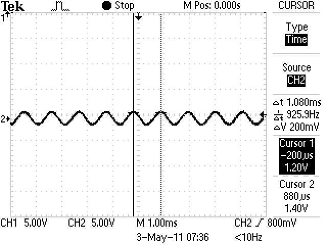
(Click to Enlarge) Oscilloscope reading of a sinusoid input into ear when the sensor measures an obstacle at a distance of 2.5 ft. This outputs a frequency of 925 Hz, and the peak to peak is around 2.5 V.
At 2.5 feet, or 0.76 meters, the frequency is lower at 925 Hz, as expected. It is now in the second bin of volume shift, so the amplitude has dropped by 1/2. We measured a peak to peak around 2.5V, which is indeed a drop of 1/2.

(Click to Enlarge)Oscilloscope reading of a sinusoid input into ear when the sensor measures an obstacle at a distance of 6 ft. This outputs a frequency of 833 Hz, and the peak to peak is now around 1.25 V.
At 6 feet, or 1.83 meters, the frequency is even lower at 833 Hz, as expected. It is now in the third bin of volume shift, so the amplitude dropped by 1/4. We measured a peak to peak around 1.25V, so this worked as expected.
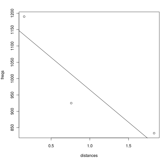
(Click to Enlarge) A plot of frequency (Hz) versus distance(Meters).
We can verify the shift in frequency from the above plot. The slope is -198.3 Hz/meter and the intercept is at 1163.9 Hz at 0m. The intercept calculated from our program was at 1377 Hz, and the slope calculated was -272 Hz/meter. Possible reasons for the discrepancy is that our program did not use the correct speed of sound, or that there may be nonlinearities that were not accounted for. In addition, it is difficult to conclude much from the 3 data points we collected. The important thing, however, is that the slopes match in signs and are close in magnitude. The user can simply adapt to any variations to the slope and intercept frequency, as long as not too significant.
Speed
We tested the device in the hallway of Duffield. The update rate of the sensors were quick enough to notice walls when walking at a normal pace. The vibrators vibrate just gently enough to notice. We did this because we do not want to cause any discomfort to the user. We were also able to feel and hear people walk in front of the device.
Accuracy
The 340 m/s speed of sound is an estimate. We measured the distance at the point when we can no longer hear the headphones. We found it occurs at 17 feet, which is 5.2 meters. This is very close to our calculated 4.98 meters. The reasons for the possible difference is that close to our maximum of 4.98 meters, the sound was shifted to the left by a factor of 32, which corresponds with a drop in 15 dB. The sound also gets very low, so is difficult to hear as well. It became difficult to tell if we heard something or not. Another possible reason is that the speed of sound may not be 340 m/s that day, but faster due to weather variations.
Safety
Our device is designed to improve user safety and is safe itself. The device uses low voltage (0-9V). The only part of this device that is not always 0-9V is the back of the transducer which could reach plus or minus 200V. Since the transducer is on the hat and the hat will be worn, we protect both the hat and the user by using insulating spacers. The back of the transducer should not be touched and cannot be reached without significant tampering. If it is touched, though, the user will not be hurt, but might be able to feel it (we accidentally experienced this).
Other safety features that we have are switches. There is a power switch that can turn the entire device off and a switch to stop sending INIT signals to the sensors, that can be used to stop the device in case of malfunction.
Interference
Our project did not interfere with other projects inside or outside of the room. The frequency of our SONAR is very high (50kHz) and is not in the audible range. The ultrasound did not interfere with wireless or television broadcasting as it is much lower in frequency.
Usability
Anyone can use this device. It is meant for the visually impaired, but the construction of it allows for anyone to use. People who are both visually and hearing impaired can also effectively use this device in the vibration mode. The size of the hat and hip-pack are adjustable so they can fit on anyone. All that the person needs to do is turn the device on, select a mode for user feedback, and learn how to interpret the vibrations or sounds from the device.
Conclusions
Analysis
We met our expectations in that we used two sensors and gave useful feedback to the user. For the headphone mode, the frequency of the sound increases as the distance to an obstacle decreases. For the vibration mode, the intensity of the vibration increases as the distance to an obstacle decreases. We also account for obstacles that are slightly to the left or right of the user. If the right motor vibrates more intensely than the left, it means that there is an obstacle closer to the right. Thus, the user should intuitively move away from the obstacle on the right without having reached it.
We did slightly change our original plan. We wanted to implement two modes of operation based on distance--long distance and short distance. Although the sensors are capable of detecting obstacles of up to about 10.6 meters (35 feet) away, we decided to limit the detection to about 5 meters (16 feet). We decided that this was a good distance to work with since obstacles within 5 meters are most important to users.
Things that we would like to do in the future include adding more sensors and making the circuit even smaller to make it more portable. We would make the vibrators stronger, so the user can feel them, or come up with other hardware interfaces for communicating with the user.
We could also make a secondary device that transmits the SONAR pulse signal to be received by our sensor independent of what the sensor sends out. For example, at cliff edges or sudden drops, our user will not know about the absence of obstacle, but with a transmitter attached to the cliff's edge, the user will receive loud pulses near the edge and know to stay away. A different mode could be used to find braille letters, where a transmitter attached to the braille words would lead the user to them.
In the future, we may want to design a smaller custom PCB than the one we used because we ended up using only 10 port pins, including ground. We did not use any of PORT A, nor much of the PORT B and C. Not only this, we used up only 11.7% of our program memory and only 18.8% of our data memory. Our program was very compact because communication with sensors, headphones, and vibrators were simple. It did not require much memory other than the sine table. Our capture mode was in the range of ms and did not require such accuracy, so we could have modeled it in program mode without interrupts. The PWM mode for the vibrator could also have been done in the program, since it was slow enough compared to the global clock. In addition, our PWM could also be replaced by a Digital to Analog converter. This means a smaller and cheaper protoboard could be used to equal effect.
Standards
Though the standards described previously just suggestions, our project met those suggestions. We provide redundancy through the use of two sensors, especially for the important 10 degrees directly ahead of the user where the user may collide with objects. When we tested SensCap, both vibrators or both earpieces reacted strongly when approaching a wall, so even if one sensor fails, the other would effectively alert the user. SensCap satisfies individual differences because it gives the user a choice between vibration mode and headphone mode. When in a loud area, vibration mode may be used. It may also be useful to those who are also deaf. SensCap underwent tests to make sure the device operates effectively and reliably, as detailed above. The low cost is included below.
Intellectual Property Considerations
We did not reuse code or use code in the public domain. A similar implementation was done in "What it is like to be a bat: A sonar system for humans" by researchers at Boston University. Their implementation included doppler shifts for speed and a sensor that can detect echolocations from all angles, rather than our 15 degrees. Their implementation is more complex than ours. We may not have patent opportunities for our project. However, our design may be superior because it implements the system with much less expensive sensors. There are also many other devices designed for assisting the blind, as detailed in Multisensor Strategies to Assist Blind People. Their designs are more sophisticated, utilizing multiple sensors, which offers more detail about distance and angle. Our SensCap may be superior due to its cheaper cost while still maintaining comparable information and user interface.
Ethical Considerations
We adhered to the IEEE code of ethics by "accepting responsibilty in making decisions consistent with the safety, health, and welfare of the public, and to disclose promptly factors that might endanger the public or the environment." We were respectful of others while working on this project by cleaning up after ourselves and keeping distractions to a minimum. To prevent accidents, we were careful to not leave a hot soldering irons unattended.
The only factor that might endanger the user of this device is if he or she touches the back of the transducers. We stated above in our safety descriptions that the sensor could reach voltages of plus or minus 200V. This is not enough to hurt anyone, but it is enough to feel. For safety reasons, we placed an insulating spacer between the transducers and the hat. This is so that the user can never acutally touch the high voltage parts without significantly tampering with the device.
We were "honest and realistic in stating claims or estimates based on available data."
We also "sought out, accepted, and offered honest criticism of technical work, to acknowledge and correct errors, and to credit properly the contributions of others." In the "Acknowledgements" portion of this web page, we thank those who have helped us with our project and cite sources.
Legal Considerations
Our project does not violate any regulation that we are aware of. The frequency used for our ultrasonic sensors is 50KHz and does not violate any FCC regulations
Appendix
Software Code
Sensor_Code.c - Our final version for using our two sensors.
Schematics

(Click to Enlarge) A schematic of our circuit.
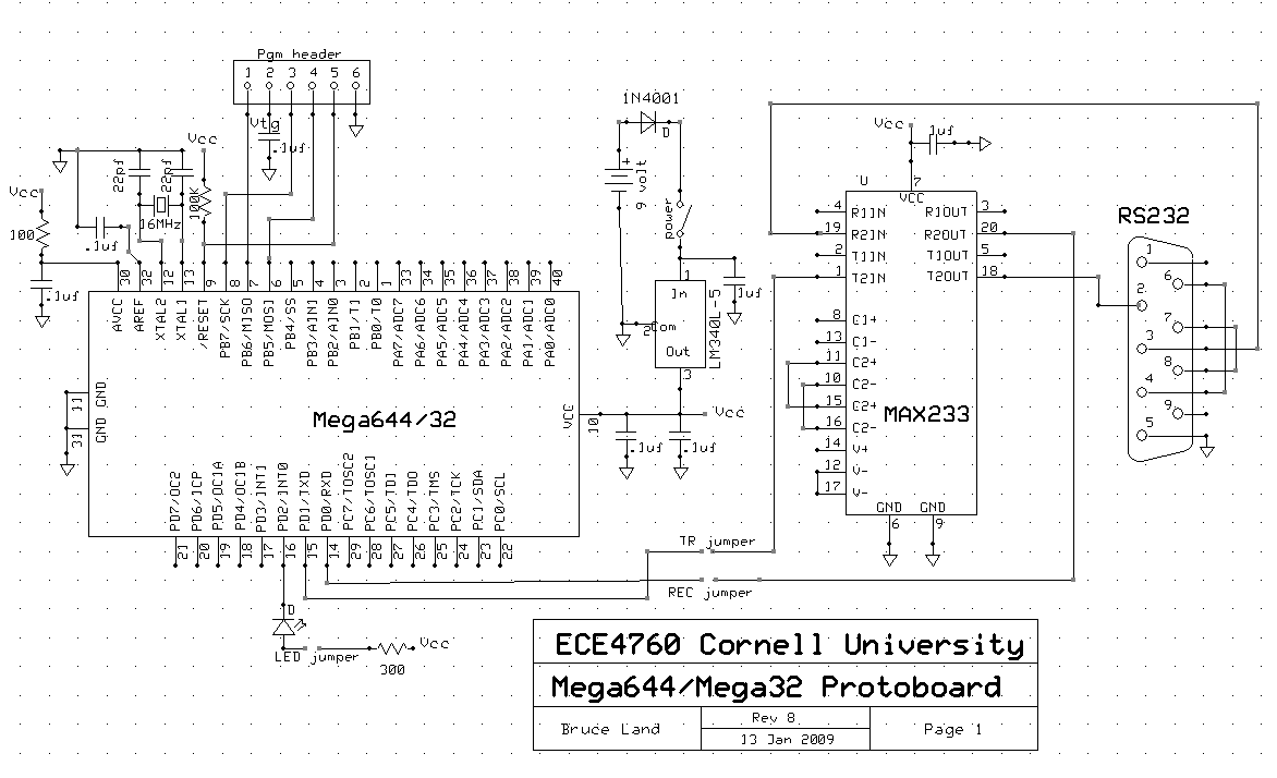
(Click to Enlarge) Schematic of the custom printed circuit board designed by Professor Bruce Land.

(Click to Enlarge) Layout of the custom printed circuit board.
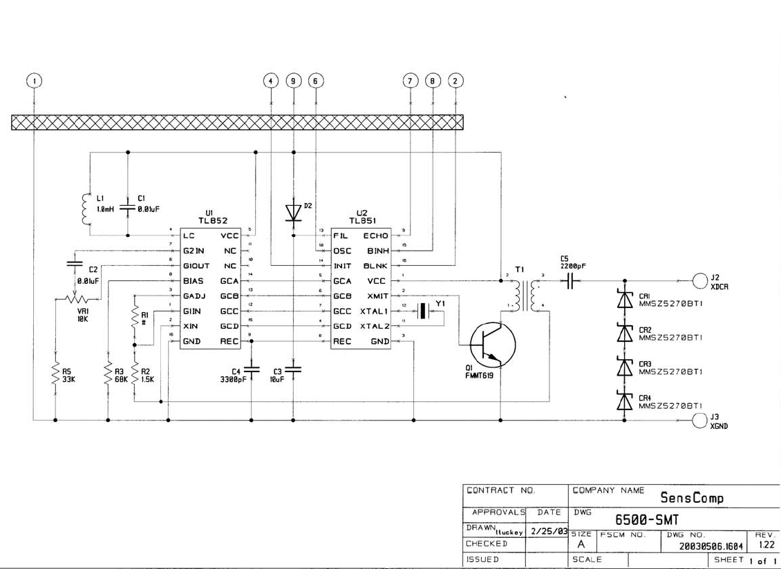
(Click to Enlarge) Schematic of the SenseComp 6500 Sonar Ranging Module.
Parts List
| Part Name | Part # | Vendor | Cost |
|---|---|---|---|
| Ultrasonic Sensor | SenseComp7000 | Previously Owned | $0 |
| Sensor Ranging Module | SenseComp 6500 | Previously Owned | $0 |
| Hip Pack | Previously Owned | $0 | |
| Baseball Cap | Previously Owned | $0 | |
| 9V Battery | ECE 4760 Lab | $2.00 | |
| 9V and AA Battery Holders | ECE 4760 Lab | $0 | |
| Headphones | MB770G/B | Previously Owned | $0 |
| Vibrating mini-motor | DCM-382 | All Electronics - ECE 4760 Lab | $0 |
| Complete Custom Target Board | Custom | ECE 4760 Lab | $7.00 |
| Microcontroller | Atmel MEGA644 | ECE 4760 Lab | $8.00 |
| Rocker Switches | 30-16096 | Ohm Electronics | $5.98 |
| AA Batteries | AA Batteries | Amazon | $5.34 |
| Solder Board and Components | ECE 4760 Lab | $10.00 | |
| Total | $38.32 |
Tasks List
| Task | Group Member(s) | Hardware Design | Both |
|---|---|
| Software Design | Liuyuan |
| Portability | Zeynep |
| Website | Both |
References
Data Sheets
Vendor Sites
Background Papers
B. Ando, Graziani, S..(2009). Multisensor Strategies to Assist Blind People: A Clear-Path Indicator. IEEE Transactions on Instrumentation and Measurement. v.58. n.8.
Acknowledgements
We referred to ECE 4760 Lab 4 to desgin our circuit for our motor Lab 4 Circuit Design
We would like to thank Professor Bruce Long for his guidance. We would like to thank the TAs of this course for helping us with our project and keeping the lab open when we really needed it. We would also like to thank Zeynep's brother, Murat, for giving us his old sensors and chips.