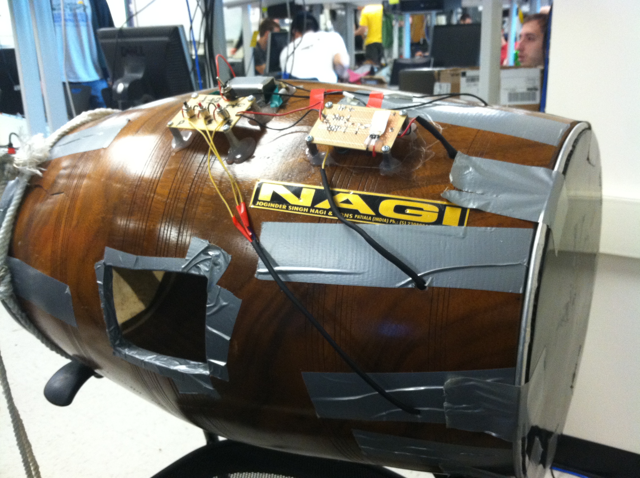
"An electronic version of a North Indian percussion isntrument with Record and playback capabilities."
project soundbyte
Introduction
For our final project, we decided to create an electronic version of the Dhol, a North Indian percussion instrument. The final design takes a traditional dhol and was modified to electronically produce three different sounds, as well as be able to record a drum sequence and have it play back, for learning purposes.
The drum utilizes several peripheral amplifiers and Analog-to-Digital Converters (ADCs) plus an Atmel AtMega644 to produce the different sounds. A drum hit is recorded when one of three independent force transducers are triggered by vibration, depending on which one was triggered, the corresponding sound is played.
For reference, we will be using the following vocabulary (below is an image clarifying this):
Dhagga – this is typically the “bass” side of the Dhol
Tilli – The “Treble” side of the Dhol
Stick – In our case, the “stick sound” will refer to the sound produced when the drummer hits the wooden top of the drum with his stick
High Level Design top
Rationale and Sources
The Dhol is a widely used percussion instrument, and, though originally a folk instrument from Northern India, has gained popularity throughout the world. In fact, some musicians, such as John Powell, used it in soundtracks for different movies, such as the Bourne Supremacy. Competitive Bhangra Dance Teams across the world also use it during their performances (Bhangra is a dance style that utilizes the Dhol for its music).
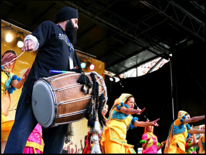
Figure 2: Dhol Player performing. Image courtesy of Google Images.
One of the problems with dhol playing in competitions and in certain other areas as well is the lack of sound. While the Dhol itself is a very loud instrument, as with most percussion instruments, it is not loud enough to be heard in the back of the theaters and auditoriums where such competitions are hosted at, particularly because of the loud music going on in the background. Some of the more professional Dhol players attempt to put clip on microphones on to their Dhols, but it does not completely help to make the audio sound better, plus, because it is clipped on the side, it is susceptible to noise generated by the drum bouncing off of the dhol players body as he moves around or starts playing very aggressively. Hence we decided to create an electronic version of the drum, which is able to output a sound only when the dhol player strikes, and can be clearly heard over the speaker system when played.
In addition to this, since we were both musicians, we wanted to create a project that could be used as a tool for musicians, and also one that would be useful for a large group of people. Many popular songs and dances in India use the dhol as a basic beat, and we thought it would be interesting to create some of our own dance beats. We also had our own experiences to help reach this idea. Eashwar is a South Indian percussion instrument player, as well as a former member of the Cornell Bhangra Dance Team, and so he naturally gravitated to an idea that melded electrical engineering and percussion together. Ajay has had a wide exposure to several different North Indian percussion instruments, and also, being a Mechanical Engineer, wanted a project with some decent hardware setup involved. Combining all these qualities and desires led to the creation of an electronic dhol.
“Let’s do something likerock band, except we're uinge a dhol instead of a drum set…..so Bhangra Band?”
- Ajay Phadke, during our brainstorming session
Standards
We followed the basic standards set by IEEE, ISO, and ANSI while creating this module. We did not use any communication protocols that would require following standards set outside of these three organizations.
User Interface
Our approach to the User Interface is to allow the drum player to have simple access to all of the interactive features of this device. There are two parts to the UI. One is of course the actual drum. The user can hit either side of the drum, or the top platform closest to the treble side, to produce the three different sounds: Tilli, Dhagga, and Stick. The drum membranes can be struck in any matter, stick or hand, and provided with enough force the sound will get triggered. We allowed the user to be able to change the sensitivity of the drum, anywhere from even the slightest hit can trigger it to the hardest hit not being able to trigger it at all. This gives the user a wide range of sensitivities to work with.
We also gave the user the ability to easily record and play back a sequence that he or she performs. At the touch of a button, the user starts the recording mode. Once he or she is done playing the intended sequence, the user stops the recording with another button. The player can then activate the drumming sequence that was just recorded by pressing another button. Users would also have the ability to play along with the recorded bit, as to practice their skills.
The interface will be described more in the Hardware and Software Sections.
Logical Structure
In order to do this project, we took a sample dhol and modified, as we felt it would be easier than to build an entirely new dhol from scratch.
The electronic dhol synthesizes three different sounds: tilli (where we tap the treble drum head with a stick), dhagga (where we tap the bass drum head with a stick), and stick (where we tap the body of the dhol with a stick) Each of the synthesized sounds followed the following sequence:
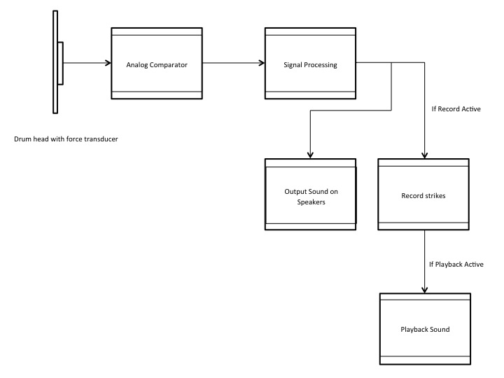
Figure 3: High Level Design
The main signal translation work is done outside of the microntroller. By the time it reaches the Mega644, the signal was entirely digital, and from the point of view of the MCU, is nothing more than a switch being turned on and off. The MCU takes these digital signals and processes it in order to produce the three different tones.
The vibrations that are induced when we strike on the tilli, dhagga, or stick are sensed by the force transducer and the transducer outputs oscillatory signals. These force transducers allow us to convert mechanical energy from the strike to a voltage signal (they are essentially piezoelectric signals), and we can use this to play electronic sounds in real-time. The force transducer signals were then passed to analog comparators, or Schmitt triggers, which converted the signal to a 0-5V scale that could be read by the Mega644 Chip.
After passing through the Schmitt triggers, the signal was inputted into the Mega644 chip and processed using code written in C. When the signal is 5 volts, the program registers it as a strike and outputs the corresponding computerized sound. At the same time, with the push of a button, we can enable recording. When this button is pushed, all the strikes are stored in the microcontroller. When the stop recording button is pushed, this functionality will end. Pressing the playback button will then output the strikes that were just recorded.
Hardware/Software Tradeoffs
We encountered several tradeoffs when designing this system. The first tradeoff we found was the resolution vs. cost of the force transducers. The more expensive the transducer, the higher sensitivity we would see. Higher sensitivity would generate higher signals for a given strike. If we had a transducer with high enough sensitivity, we may not have needed the non-inverting Operational Amplifiers (Op Amps) to bump up the voltage so the Mega644 could read it. For a consumer device, the main driving factor is price, and so we found it beneficial to purchase less sensitive transducers and add amplifier circuitry.
Another tradeoff we encountered was the implementation of analog comparators in Atmega644 vs. building our own. Building our own analog comparator circuit counts against our budget whereas the using the on-board analog comparator requires only two resistors. The tradeoff is that the onboard analog comparator requires an input pin. Although building our own analog comparators increased the cost of our system, we kept the input pins available and we had added control of the comparator by using potentiometers to control the threshold. In addition, users can easily change the comparator value using the potentiometer, instead of having to program it each time.
Patent, Copyright, and Trademark
In terms of any patent infringements, we believe that we are not violating any existing devices while creating this one. Exhaustive searches on Google, Yahoo, and Bing produced results related to electronic drum pads, but no electronic dhols. There were some dhols that had electrical modifications made to them, such as having embedded LEDs that lit up while playing. However, no results have shown up regarding a full electronic dhol as we are doing.
Hardware: A Closer Look top
The hardware component of this system is simple and can be easily reproduced. In addition to the AtMega644 microcontroller board, we used LM358 op-amps, resistors, 10kΩ potentiometers, wire, alligator clips, and force transducers. Figure 3 below shows a photo of the final hardware setup. Schematics of our individual components can be found in Appendix B
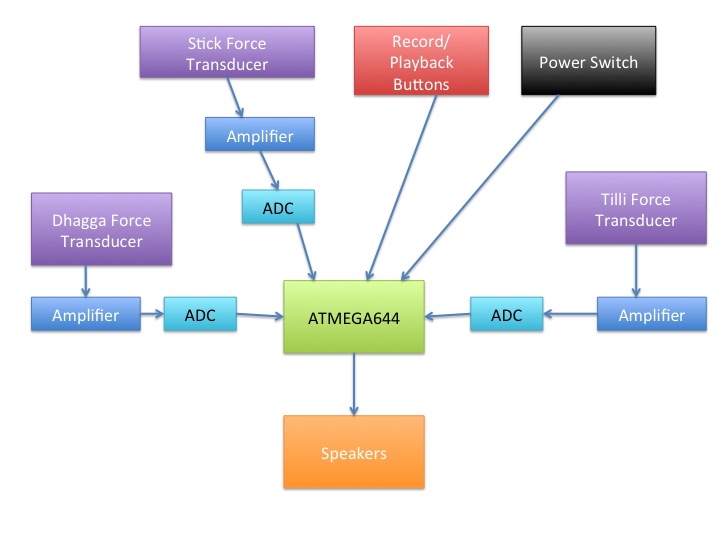
Figure 3: High Level Hardware Design
The Hardware Design is split up into the following stages: Force Transduction, Analog Comparator, Output to Speakers.
Force Transduction stage
The AtMega644 microcontroller takes in electric signals in order to output the computerized sounds of the dhol. In order for us to use the microcontroller, we must first convert the mechanical energy from a drum strike into an electrical signal. This is accomplished by attaching force transducers to the insides of the tilli head, dhagga head, and on top of the dhol itself.
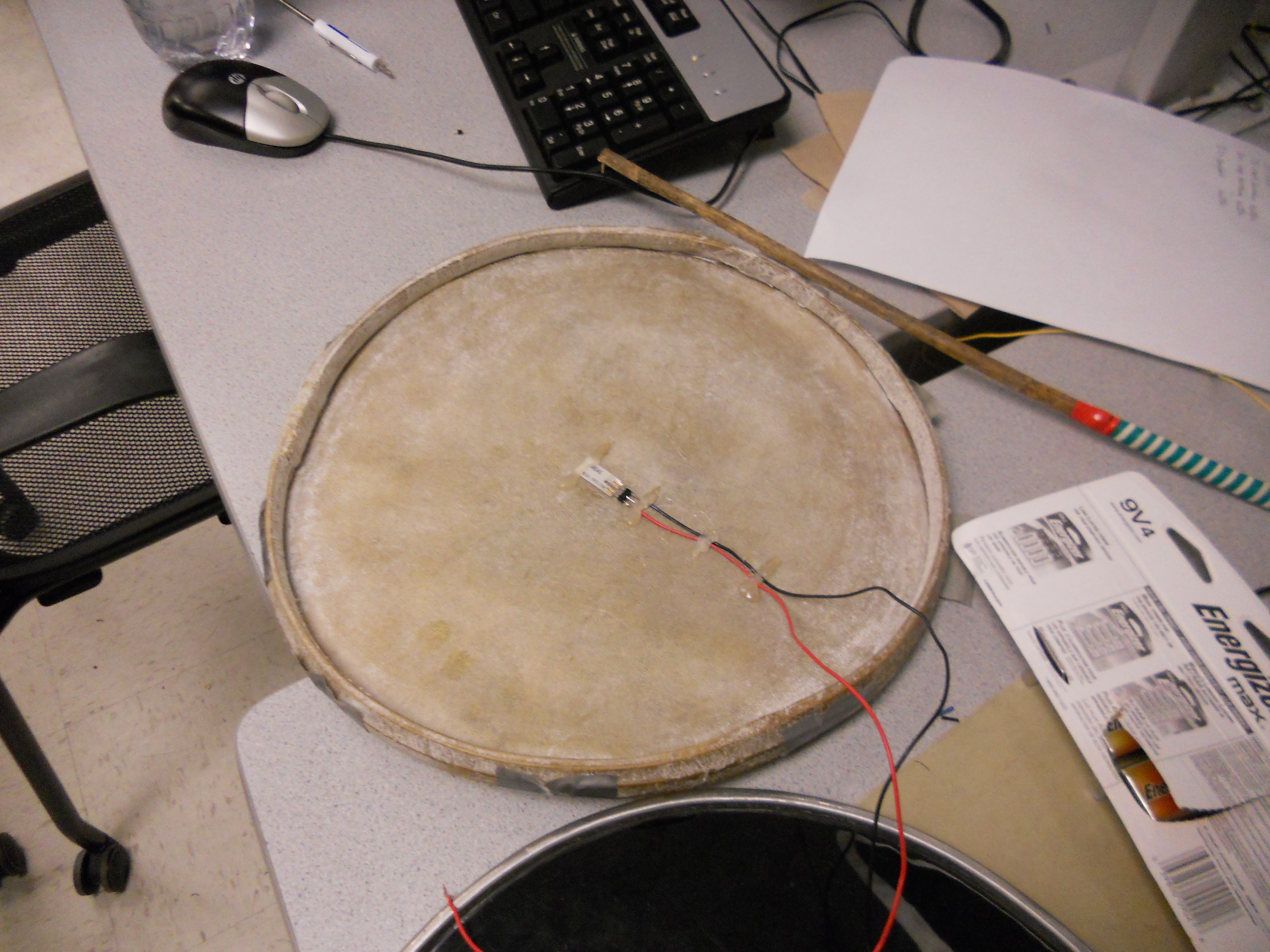
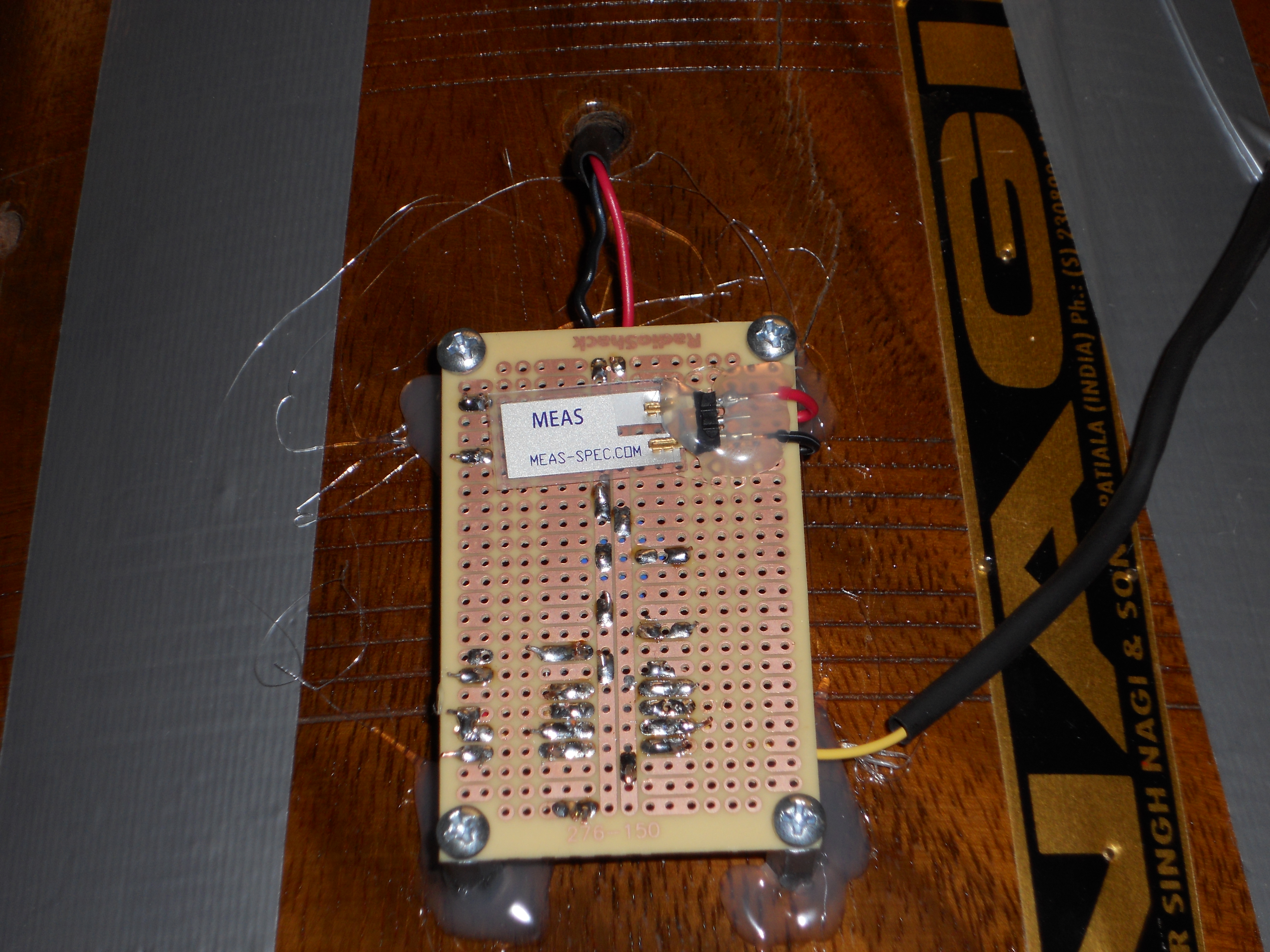
Figure 4: (Top) Force Transducer on Dhagga Head. (Bottom) Force Transducer for the Stick Sound.
The force transducers have a sensitivity of 50 mV/g. When simply flicking one of the force transducers, we can easily generate 10 to 20V. However when attached to the back of the dhol heads and the top of the body, the resulting force on the transducers is greatly reduced, and we can only output on the order of several hundred mV. When attached to the dhol heads and the body, the force transducers output a decaying sinusoidal signal. Because the output amplitude is very small, we passed this through analog comparators to convert the signals into values our microcontroller can accept.
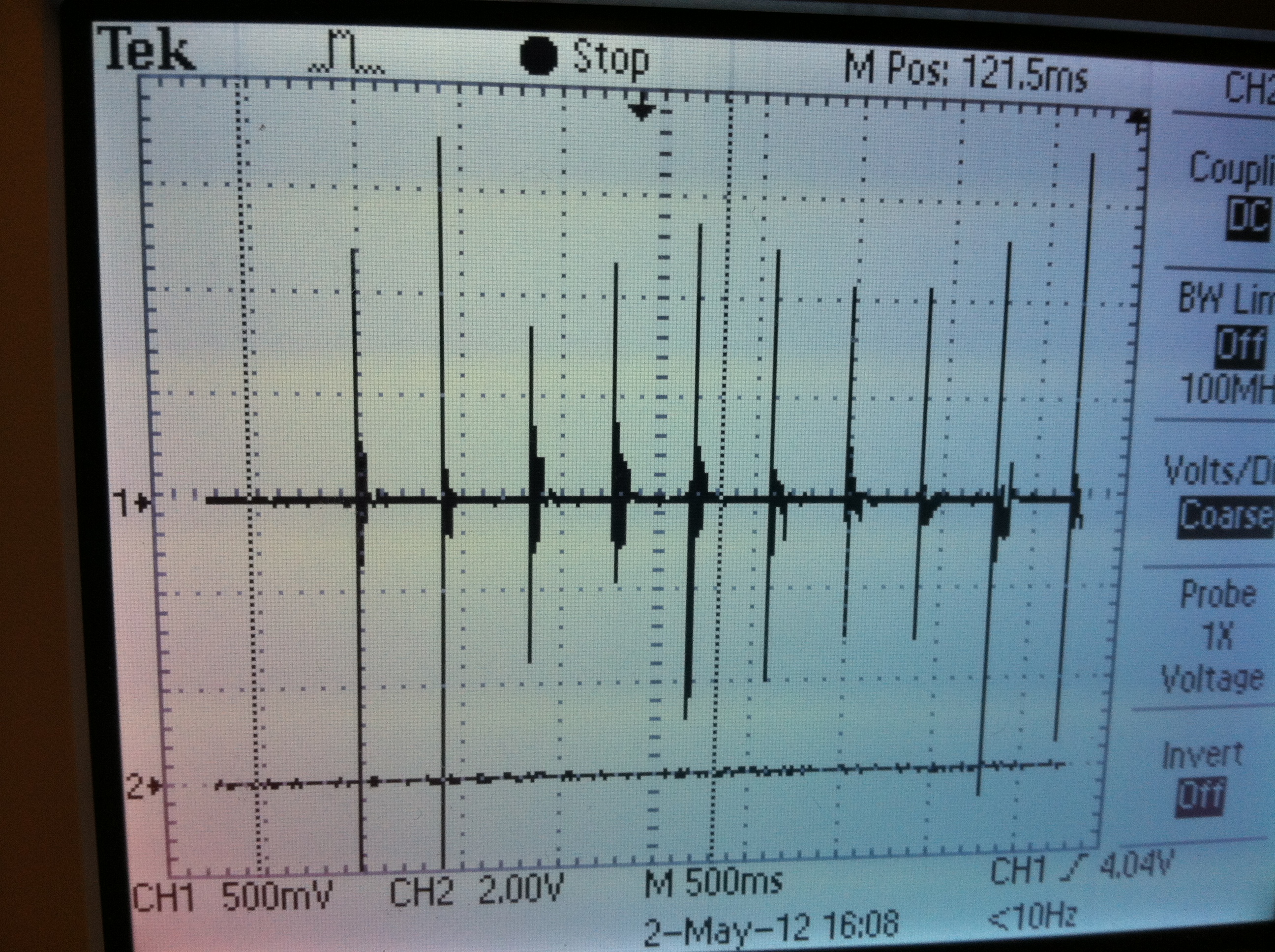
Figure 5: Force Sensor Input
Analog Comparator stage
Each force transducer signal was passed through an analog comparator to convert the variable amplitude signal to a 0 to ~5V square wave output of same frequency. The main components of the analog comparator include an LM358 op-amp and a 10kΩ potentiometer. The LM358 upper voltage rail was set to 5V and the lower voltage rail was set to 0V. The positive terminal of the op-amp was connected to the force transducer. The negative terminal of the op-amp was connected to the 10kΩ potentiometer, and this served as our threshold limit. When the force transducer signal was greater than the threshold, then the comparator would output 5 V and 0V otherwise.
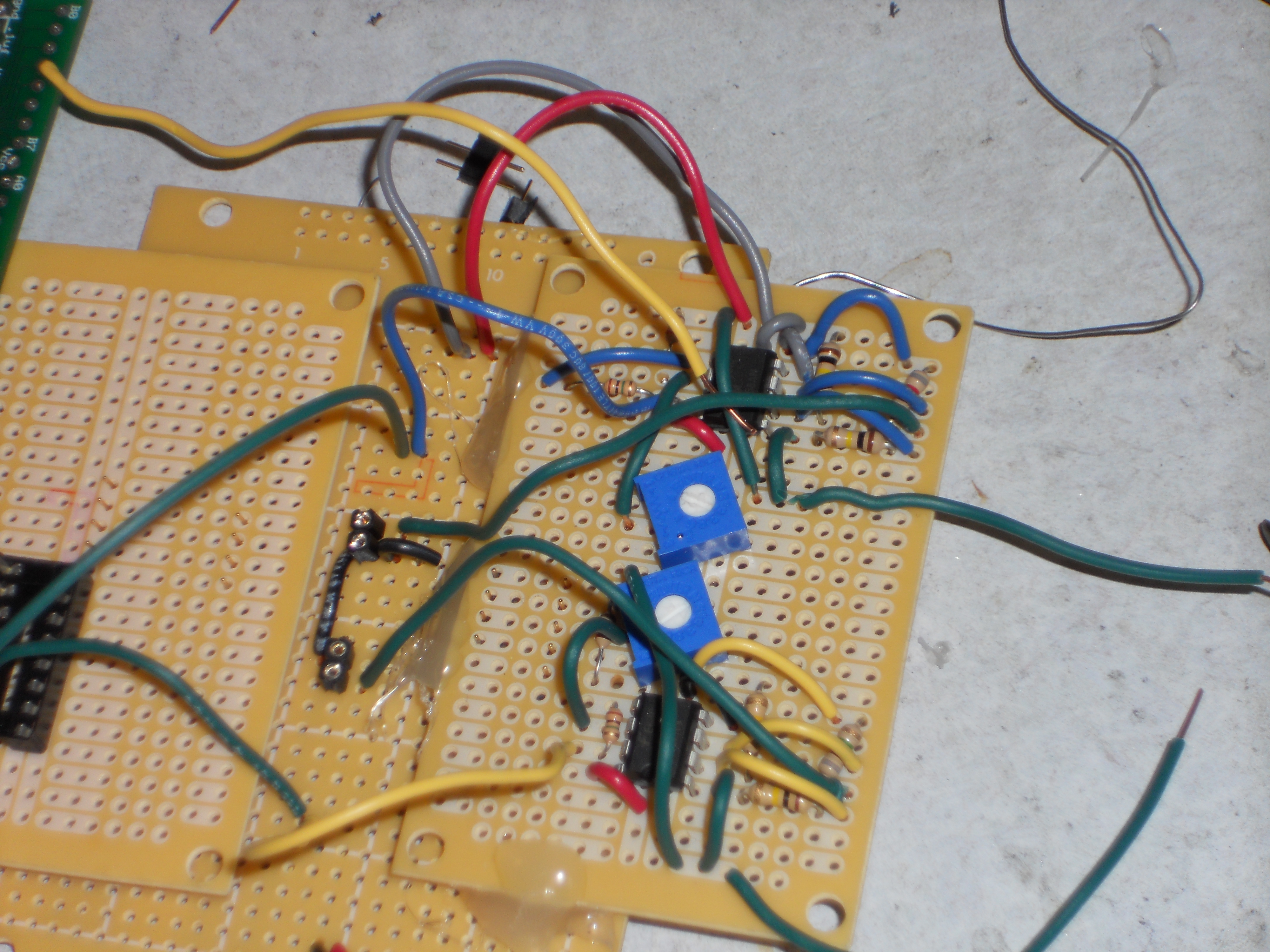
Figure 6: Analog Comparator and Non Inverting AMplifier
The microcontroller accepts inputs that are 5V or 0V so it was necessary to convert the force transducer signal to a similar scale that the microcontroller can accept. The output from the analog comparator is inputted into the microcontroller and the rest of the signal processing is handled by the software which is discussed below.
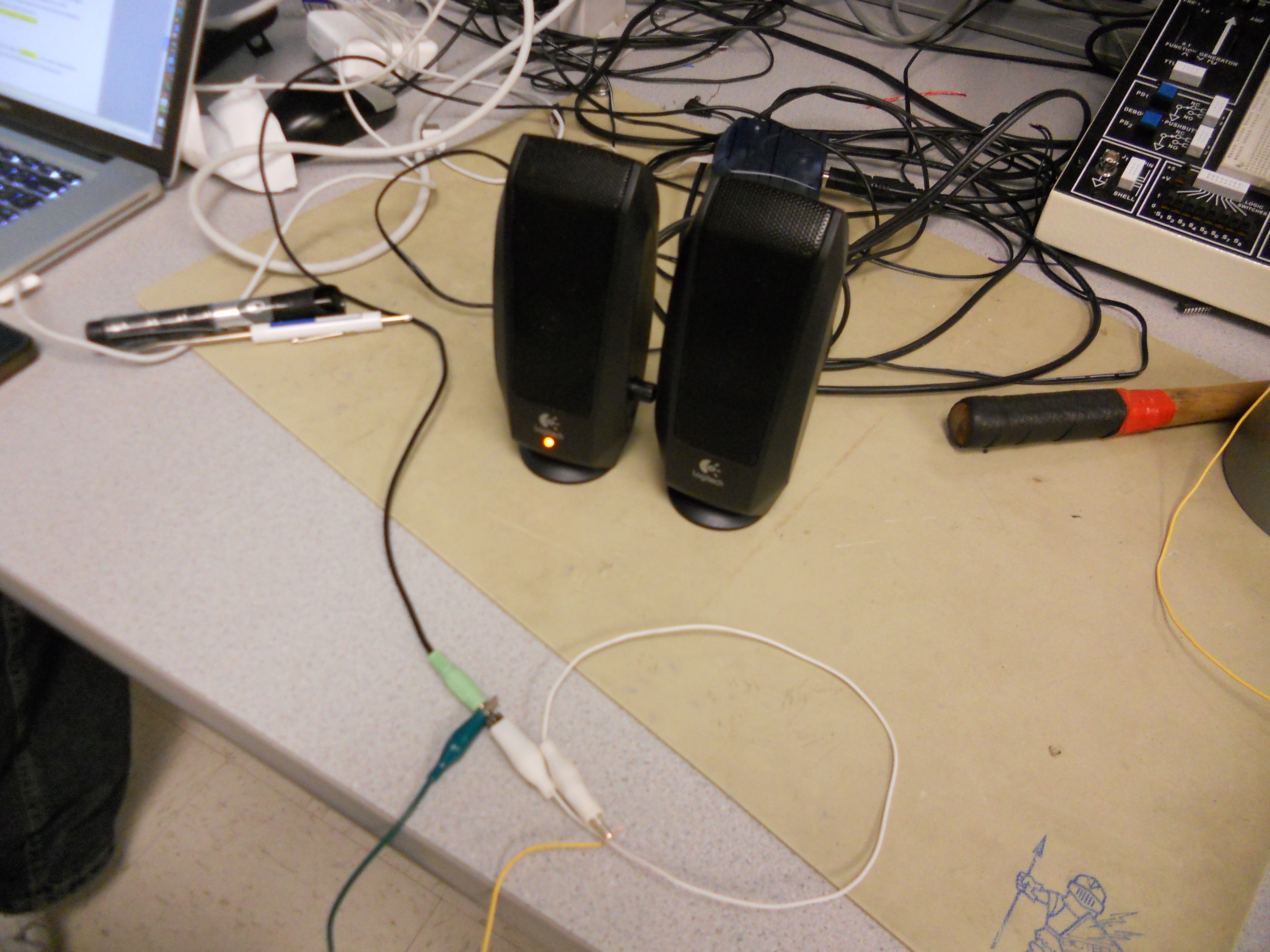
Output to speakers
The output from the microcontroller, which is a pulse-width-modulated signal that represents the tilli, dhagga, and stick noises is passed into a 10kΩ potentiometer (which serves as on-board volume control) and then passed to the speakers, and the speakers output the sound.
Push Button Implementation
The following picture shows how we had implemented a Push button to emulate the push button that is used on the STK 500
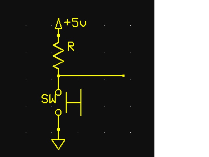
Figure 4: Switch Schematic generated by ExpressSCH
3 of these switches were implemented for the Record Start, Stop, and Playback
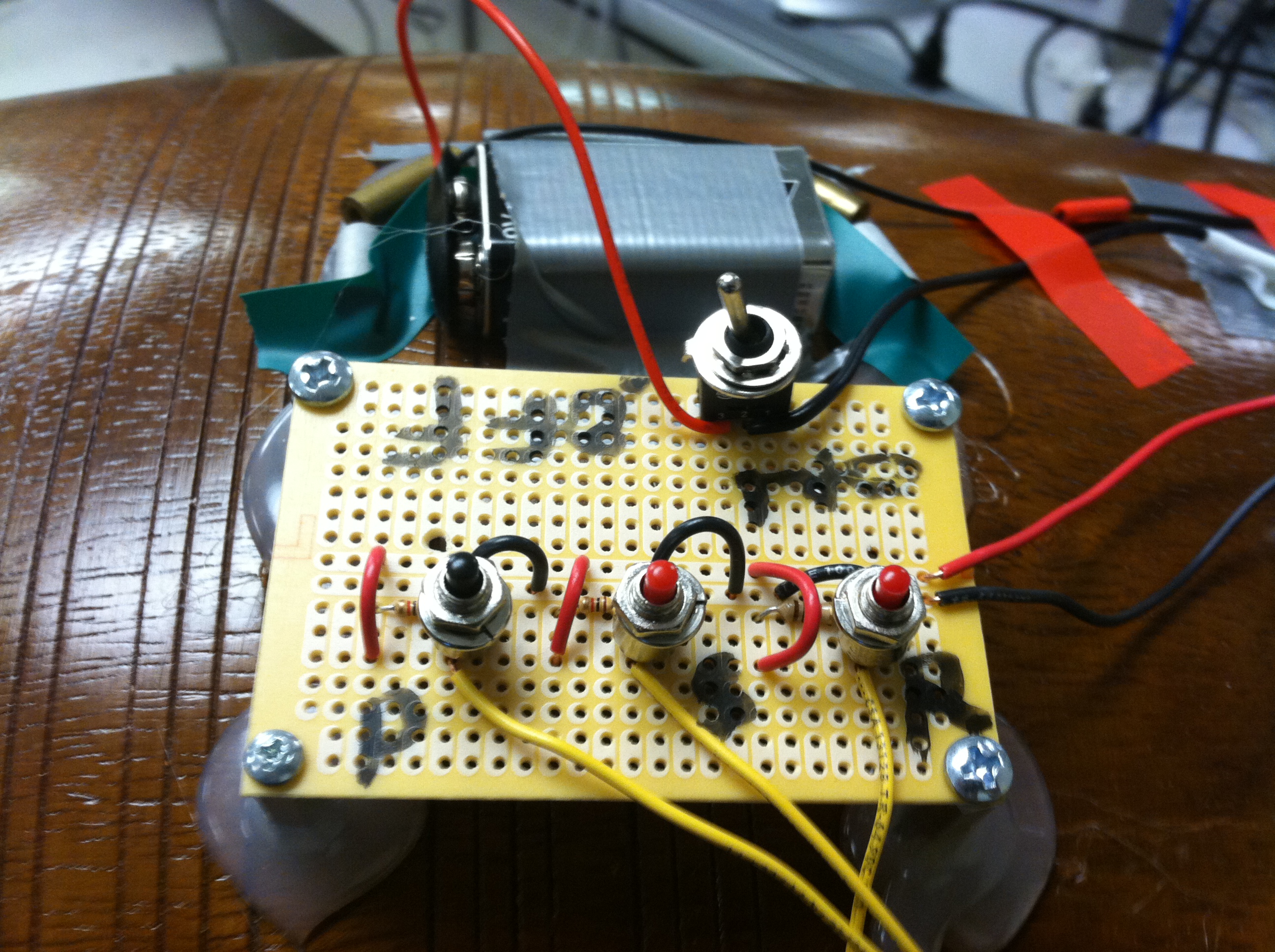
Figure 5: All 3 Switches (from right to left): Start Record, Stop Record, Playback
ATMEGA644
The following is a picture of the ATMEGA644 as well as the ExpressPCB schematic drawing
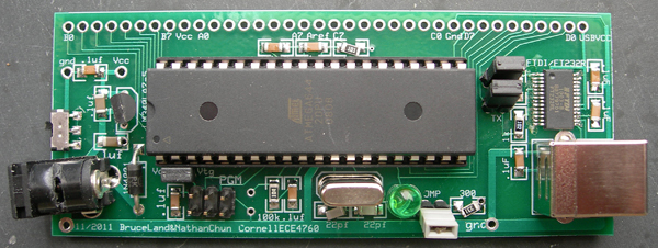
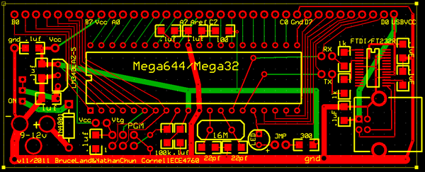
Figure 6: (Top) a Populated ATMEGA644. (Bottom) the ExpressPCB Schematic of ATMEGA644. Images property of ECE 4760, Cornell University
We used Pins D0-D1, D3-D5, and D7 for our drum.
Software Design top
A fully commented version of our code is listed in Appendix A. Our code is based off of an example FM Synthesis (LINK) code from ECE 4760 Spring 2012 Lab Exercise 3.
Sound files
Computerized sounds representing the tilli, dhagga, and stick were recording using Audacity (LINK) sound processing software. The sounds were recorded from the iPhone app Dhol-E (LINK), an application that simulates a dhol by using touch features to activate different sounds. We sampled the sounds at 16 kHz using Audacity and outputted .wav files for the tilli, dhagga, and stick. These sound files were then processed by our MATLAB Code (See Appendix A), which converted the .wav files to 8-bit character arrays. These 8-bit character arrays were then stored in the Flash memory in the AtMega644 microcontroller.
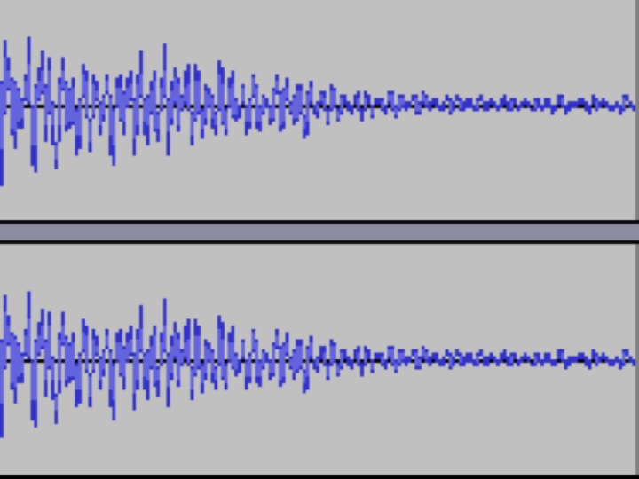
Figure 7: Example Wave Form
Sound envelope
We noticed that the sound files were clipping on and off when the sounds were beginning or ending. To output a crisper and higher quality sound, we used MATLAB to create a 75ms rising envelope for the beginning of the 8-bit character array, and a 75ms descending envelope for the end of the 8-bit character array. This modified array was then programmed into Flash memory in place of the original sound files.
Main Code
The main code begins by initializing the necessary variables and ports. We initialize PINB.3 to be an output because that pin is configured to output the pulse-width-modulated signal that goes to the speakers. We define PORTD to be an input, as this is where the tilli, dhagga, and stick sensors are connected, as well as the pushbuttons that correspond to the record, stop record, and playback features. We initialize the indices corresponding to each of the three sounds. These indices are used by Timer1 to access individual 8-bit values inside the arrays and set the corresponding PWM signal. We activate Timer0 with PWM, and this PWM signal is outputted to PINB.3 and eventually to the speakers as a sound. We activate Timer1 as a compare match vector running at 16 kHz frequency.
The main while loop check values of 6 inputs: the tilli strike sensor, the dhagga strike sensor, the stick strike sensor, the recording button, the stop recording button, and the playback button. When any of these are activated, the corresponding flag is set here, and the Interrupt Service Routine (ISR) uses those flags to execute the appropriate commands.
ISR
The ISR is used to output the sounds to the speaker. The ISR used here is a Timer1 Compare Vector, which triggers at 16kHz frequency, which is the sampling rate of the sound files. The ISR takes the flags set in the main function by the various inputs (tilli, dhagga, stick, record, stop recording, and playback) and executes the necessary commands to output sounds.
Triggering
We noticed that each time we would strike the tilli, dhagga, or body, the force transducers and analog comparators would output a 0-5V signal oscillating at a very high frequency. This led to our program detecting multiple hits rather than just one. To fix this issue, we implemented a counter for each sound, which allows our program to play a sound only when the counter resets to zero. We set the upper limit of the counter to a value such that it was slightly larger than the response time of the force transducer.
Signal the sound to be played
The main function takes inputs from the dhagga, tilli, and stick and sets flags for each one when they are struck. The main part of the ISR, the synthesis of the sounds, checks those flags and executes the necessary commands. If the dhagga is struck, then the dhagga flag is set, and the ISR indicates that the dhagga sound needs to be played. It will also set the index of the of the 8-bit character array that represents the dhagga sound file to 0, so that it may play from the beginning. Similar actions are taken when the tilli flag and stick flag are set as well.
Output sound
When the ISR indicates that a sound is to be played, it will set the PWM signal denoted by OCR0A to the value stored at the index of the 8-bit character array that represents the sound file. Once it sets OCR0A, we increment the index, so that the next time the ISR executes, it will set OCR0A to the next value in the character array. In this manner we produce a sound at 16 kHz. Once the end of the sound is reached, then we set the index to 0 as well as the flag that indicates that the sound has to be played. This allows the next sound to be triggered. If two sound are to played at the same time, then we set the PWM to take the average of the two values stored in the sounds files.
Recording
In the section of the ISR where we signal the sound to be played, we also added recording functionality. If the ‘recording-active’ flag is set, then we store the time at which the sound is to be played, and which note is to be played in an array. This is active until the user presses the ‘stop recording’ button. Later we can use these stored arrays and play back the sounds we just recorded
.
Playback
To provide even more functionality of the system, we implemented playback of the sounds that were recorded. This short sequence of code signals the sounds to be played based on the timing values stored in the time array and which sound is played based on the sound vector, both of which are stored during the recording function. This is then passed to the output sound stage.
Results top
Execution speed is good. The code responds to the external interrupt very well. There is almost no delay between hitting the dhol and sound being outputted. In terms of recording and playing back a sequence, it works very well. We are even able to have the recording play and be able to play on top of that spontaneously, something we had not anticipated. Accuracy in terms of timing is perfect. Everything is seemingly instantaneous. Accuracy in terms of drum sounds is also very good, given that we are working 8-bit samples at 16KHz, and when typical CD quality sound is 32-bit, 44.1KHz.
In terms of safety we had covered all external wires with heat shrink or electrical tape. We had also covered any internal wire joints with electrical tape and and/or heat shrink. There should be no risk of shock to the user or any shorts in the internal circuitry. In addition, because we are not using any wireless communications or infrared, etc., there should be no interference with other peoples’ designs
Any one can use this device. It’s very straightforward, and while it does have a string, does not require the dhol play to be standing and having the dhol strung around his/her neck. Indeed, the drum can be laid on the floor or lab or chair and still be used. Of course if the drum is dropped, then internal circuitry might get dislodged or a circuit board could break, given that there are no shock systems inside the drum itself.
Conclusion top
The Drum definitely met expectations. In fact, at the beginning we had a very simple idea in mind: Create the drum, with 3 sounds, and two modes that can be activated by a switch (traditional, where the traditional sounds are outputted, and a “enhanced” mode, where more bass sounds and higher treble sounds). However, we realized that creating these enhances sounds was not very practical, especially since the speakers could not output such sounds well, and so it was hard to judge whether the bass sounds were working. As such we scrapped that idea and had come up with the current idea to add a record and playback feature, as well as tunable Schmitt triggers to add the sensitivity-tuning feature. If we were to do this project again, we would add a couple user-friendly features, such as adding lights on the inside so the user has an easier time seeing inside, LED lights near the pushbuttons so the user can detect whether the button was actually pushed, and an on-board volume control so the user can stand far away from the speaker and still control the volume of the output. Next time we would also implement a wireless transfer of the output signal, thus eliminating the need to be near the speakers at all times. We did not these features this time because it would have increased our cost significantly.
Because we did not have to take into account any special standards, we are reasonably confident that all safety standards as applied by the IEE and ISO were followed.
Intellectual property considerations
No Patent infringements occurred as far as we known. Our code was based off of an example FM Synthesis (LINK) code provided to us on the ECE 4760 Spring 2012 Lab Exercise 3 webpage (LINK). However, the design of the system and the implementation of the sound synthesis was of our own design. We are not reverse engineering any design. As far as we know, there are no patent/trademark issues involved with our project. An extensive search on search engines yielded no results that were similar to our project. No non-disclosure agreements were signed in order to receive any parts. Because there are no similar designs published yet, it is possible that we can patent our design.
Ethical and Legal Considerations
The Electronic Dhol project is consistent with the IEEE Code of Ethics. This design in no way endangers the safety, health, or welfare of the public. The goal of our project is in keeping with the IEEE standards, because we are creating a technology that promotes the public’s welfare through music and rhythms. Music can bring communities together in an enjoyable environment.
We have been honest and realistic in making claims for this device: no where we have claimed that the device is 100% accurate in producing dhol sounds, or that the record/playback feature is completely accurate, as that would untrue and unethical. We can say however, that the sounds produced are reasonably accurate and that the playback outputs sounds with a reasonable accuracy. Also, designing this device has furthered our understanding and knowledge of technology and the design process, which is also promoted by the IEEE Code of Ethics.
Throughout the project, we have accepted and offered honest criticism of technical work, and properly credited others for any contributions to our project. At the same time, we have assisted fellow classmates in following this code of ethics as they design their projects. We have fairly treated all people regardless of race, religion, gender, disability, age, or origin, and have avoided injuring people, their property, reputation, or employment by any false or malicious actions.
We have not employed any devices that would require extra legal considerations, such as wireless transmission of signals and the FCC regulations.
APPENDICES top
Appendix A - Code
Here is the Electronic Dhol Code (in C) and the Audio to Text Conversion Code (in MATLAB)
Appendix B - Schematics
NON-INVERTING
ATMEGA644 PROTOTYPE BOARD - SCHEMATIC
NON-INVERTING AMPLIFIER - SCHEMATIC (Images courtesy of Wikipedia)
ANALOG COMPARATOR (SCHMITT TRIGGER) - SCHEMATIC (Image Courtesy of ECE 4760)
Appendix C - Budget
| Part Name | Part Number | Vendor | Unit Cost | Qty | Total Cost | Comments |
| Dhol Accessory Part 2 | -- | dholetc.com | $59.99 | 1 | $45.00 | https://www.dholetc.com/dhol_accessory_2.php |
| NOTE: We only used part of the accessory pack. | ||||||
| Force Transducer | 605-00004-ND | Digikey | $3.53 | 3 | $10.59 | http://search.digikey.com/scripts/DkSearch/dksus.dll?x=0&y=0&lang=en&site=us&KeyWords=605-00004-nd |
| Mega644 Chip | -- | ECE 4760 Lab | $6.00 | 1 | $6.00 | |
| Push Button (3-pack) | 275-1571 | Radio Shack | $3.19 | 1 | $3.19 | |
| Toggle Switch | 275-0624 | Radio Shack | $3.19 | 1 | $3.19 | |
| 9V Battery | -- | $2.00 | 1 | $2.00 | ||
| Header Pins/Sockets | -- | ECE 4760 Lab | $0.05 | 29 | $1.45 | |
| DIP Socket | -- | ECE 4760 Lab | $0.50 | 1 | $0.50 | |
| Op-Amp | LM358 | ECE 4760 Lab | $0.00 | 1 | $0.00 | |
| Op-Amp | LM358 | Personal | $0.00 | 2 | $0.00 | Donation |
| 10 kΩ Potentiometer | -- | ECE 4760 Lab | 5 | $0.00 | ||
| Solder Boards | -- | Personal | $0.00 | 3 | $0.00 | Donation |
| Dhol Body | -- | dholetc.com | $0.00 | 1 | $0.00 | Donation |
| Wires, Resistors, Misc | -- | ECE 4760 Lab | $0.00 | 1 | $0.00 | |
| Speakers | -- | ECE 4760 Lab | $0.00 | 1 | $0.00 | Lab Item |
| Target Board | -- | Personal | $0.00 | 1 | $0.00 | Donation |
| Total | $71.92 |
Appendic D - Specific Tasks
Ajay Phadke
- Developed code for sound synthesis and dhol strike inputs.
- Developed MATLAB code to convert sound files into 8-bit character arrays
- Ordered dhol accessories and other parts
Eashwar Rangarajan
- Developed circuitry for Schmitt triggers and amplifiers
- Generated waveforms for the different sounds
- Developed circuitry connecting the target board to all hardware components
Joint
- Put Dhol together
- Extensive debugging and testing
Appendix E - References
Datasheets: Force Transducer and LM358 Op Amp
Vendors: Digikey, Radio Shack, and Dhol Etc
Code Borrowed from others: FM Synthesis from ECE 4760 Spring 2012 Lab 3
Sounds: Dhol-E App
Acknowledgements top
We want to tthank Professor Bruce Land for being one of the best professors around, and for teaching an awesome class. We also want to thanks the lab TAs (Joe, Pavel, Ninoshka, and Houman) for the help they provided this semester and for keeping the lab open during the odd hours.
We also want to thank Dhol Etc for providing us with a free Dhol Body, and for Cornell Mars Rover for allowing Eashwar to use some of the Solder Boards and Solder Iron.
We also want to thank our friends and family for their support and advice.

