
In some cooking scenarios, it is desirable to achieve a specific object temperature and keep the object at that temperature. However, it is difficult to maintain a constant temperature without constant attention. To aid cooking in this scenario, we created a device that can be added to an electric stovetop or hot plate and serve as an automated assistant.
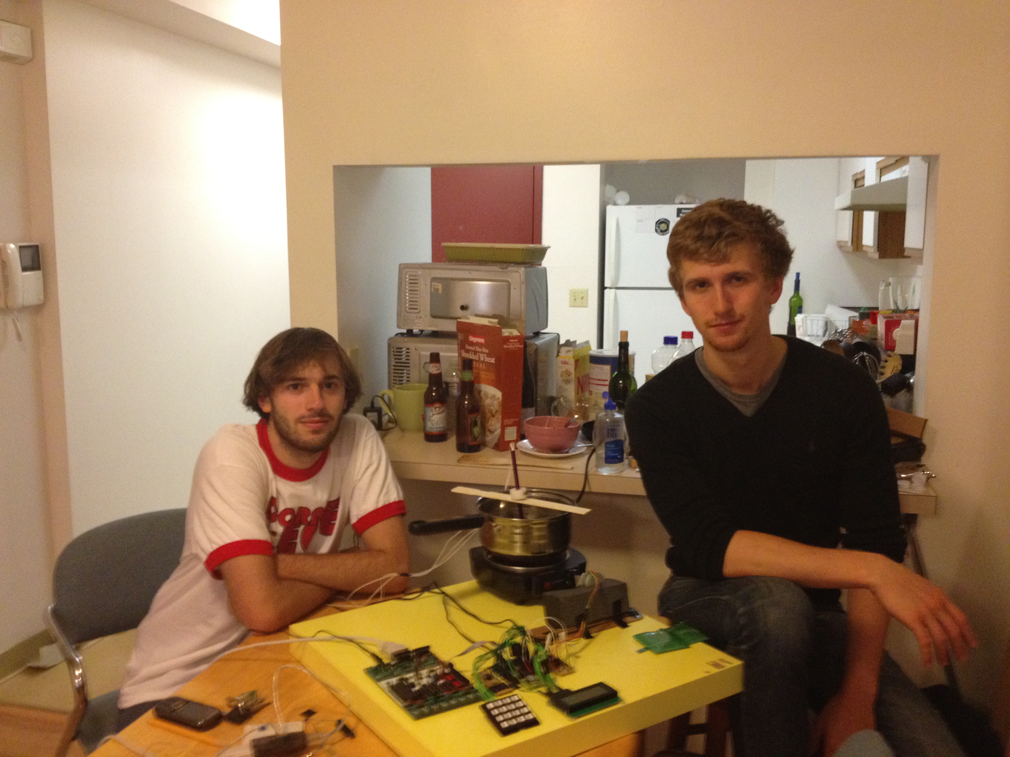
Andrew and Adam after attempting to make the perfect "microcontroller" tea for too many times
High Level Design top
The broad goals of our project were:
- measurement and control of a cooking device
- automated cooking of certain food types.
Accomplishing these goals would make the device useful for home cooking where it is difficult to keep object at desired temperature without constant attention. An early decision was made to not modify a cooking device, but rather physically manipulate the dial. This choice avoided safety problems with modifying electrical appliances and made our project easy to implement in existing cooking systems. All of our testing was done on a single electric burner, but the project could be easily used on other electric burners. It has not been designed to work with gas burners which require lighting.
Once the device is attached to the dial of the electric burner, the desired position must be determined by a controller using temperature measurements. We have built two multi-purpose temperature probes. The first probe uses a temperature sensing integrated circuit (IC) which outputs a voltage proportional to the temperature in the range of -50C to +150C with 0.2C nominal resolution and limited error. The second probe uses a negative-temperature-coefficient (NTC) thermistor and is designed to operate from 0C to +200C with larger absolute error than the IC probe. A custom circuit was designed to precisely read the resistance of the NTC thermistor over the large range of 200ohms to 15000ohms with low current through the thermistor. Simply changing the resistance in series with the thermistor would lead to excessive current that would cause self-heating and damage of the sensor. The mechanical and thermal design of the temperature probes was very challenging. The probes needed to safely and quickly transfer heat from the object to the temperature sensor while not being severely affected by the environment temperature. After considerable amount of design work and one failed probe design, we came up with a probe and probe holder with the following characteristics:
- fast heat from object to sensor
- in presence of environment temperature much lower than object temperature, still has small offset between the object and sensor temperatures
- works for internal meat temperature and water temperature with various sized cookware
- simple and cheap to construct
A proportial-integral-derivate (PID) controller was used to determine where to position the dial given the temperature measurements. Tuning the gains for the controller required a simulation because experiments are very time-consuming in slow thermal systems. The simulation was developed in Matlab and included an approximate thermal model of heating up water with a PID controller that changed the heat input to the system. Many, many thermal parameters needed to be approximated, the details of which can be seen in the Matlab files available here. The thermal simulation used after common equations and simplifications.
Before the simulation can be conducted, the heat input from the electric burner must be found as a function of the dial position (set by the controller). Based on a 1.1kW peak electrical power rating of our hot plate, we assumed the maximum heat input to be 750W. We then assumed the heat input from the electric burner was linear with respect to the dial position. This assumption causes large inaccuracies in the predicted heat input, but it avoid us making a model of the electric burner that is both complicated and specific to the electric burner we purchased. During testing, not knowing the true heat input from the hot plate adversely affected the controller but the project still remained functional. Output calculation in the controller implementation on the MCU was done as a ratio of the maximum heat input. By modifying the QMAX symbol, the controller should scale properly. Output calculation also took into account the point at which the dial turns on. On our hot plate, the device is not on between "OFF" and "LOW." Therefore, we needed to add an offset to the controller output based on the latest calibration result of the minimum on state of the hot plate. The software section details these aspects, but these considerations do affect both the performance of the controller and the applicability of our project to other electric burners.
Newton's law of cooling is used to find the heat loss to the environment, Qcool by assuming reasonable values for parameters.
qcool(i) = hair*SAobj*(Tbot(i-1) - Tenv)
where:
hair = approximate heat transfer coefficient of air
SAobj = surface area of container holding water
Tenv = ambient temperature in a hot kitchen
Tobj = temperature of the water
Then, the change in object temperature is calculated based on the net heat input
delT = dt*(qin(i)-qcool(i))/(mobj*cobj);
Tbot(i) = Tbot(i-1) + delT;
where:
mobj = mass of the water
cobj = specific heat capacity of water
qin = heat input from the hot plate
This simulation was run for various water depths (which changes heat capacity) and controller gains. Ultimately, gains were selected to produce an overdamped response since we don't want the controller to overshoot the desired temperature as that may burn the food. The results showed that derivative control had negligible effect and that during normal heating the control should saturate in the beginning, corresponding to "HI" on the hot plate.
Hardware top
Overview
The hardware setup of this project consists of a heating device (an electric hot plate in our case) of which control knob is to be attached to a stepper motor, 2 interchangeable temperature measuring probes, and control and interfacing circuitry.
The electronic hardware was designed with modularity and ease of testing in mind. A single ATMega644 MCU on a target board interfaces with a number of physically separate peripheral devices of different yet essential functions. Circuitry on the measurement board adjusts and interfaces the temperature probe outputs with the MCU. The stepper motor control circuit board controls and powers the stepper motor that is used to control the heating device. A 4x4 keypad and 4 lines x 20 character LCD screen allows the user to interact with the controller.
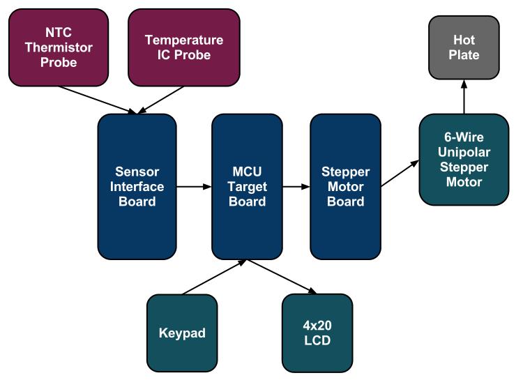
Figure 1. High level hardware system design.
Whenever we discuss a single piece of hardware, such as a temperature measurement board, it is physically separate in our setup from other devices and connected only via a detachable harness (as shown in pictures). Detachable harnessing allowed us to remove any component at any time and debug it separately from the rest of the circuit.
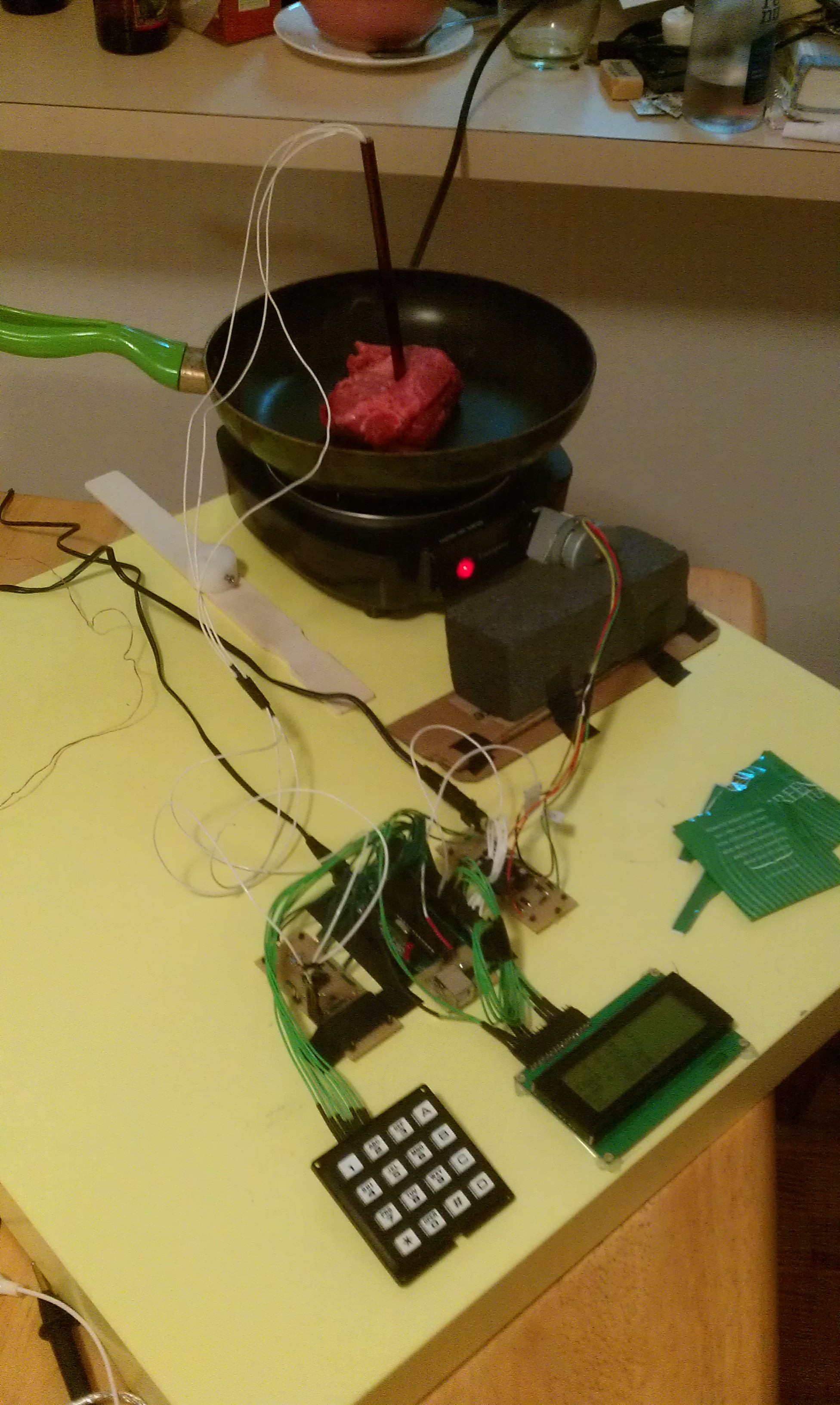
Figure 2. Complete hardware setup.
Probes
Due to our concern with reliability, accuracy, and absolute ratings, we had decided to build two different measurement probes. One (the IC probe) is based on a AD22100 analog voltage output sensor. This sensor provides an accurate (+-2%) and a very linear analog voltage output with a temperature range of -50C to 150C. The package contains three leads - +5V supply voltage, 0V ground, and analog output - which are connected by long wires to the measurement board. The sensed temperature can be easily calculated from the voltage output by a simple equation:
T = (VOUT*(5V/V+)-1.375V)/( 22.5 mV/°C)
The second probe (NTC probe) utilizes a NTC thermistor that provides a resistance across its two leads as a decreasing exponential function of the sensed temperature. While the thermistor might provide a measurement that is not as absolutely accurate (), and harder to measure due to the additional analog circuitry necessary to deal with its non-linearity, it has a much wider temperature range (). The following equation relates the resistance across the NTC thermistor and the temperature:
rNTC = Ro*exp(B*(1/T - 1/To));
Ro, B, and To are nominal values of a specific thermistor that one can find in a datasheet.
The probe design proved to be challenging as we were looking for the best and most immediate heat transfer medium between the food/water and the sensor. We first attempted to glue the sensors to a thin piece of solid aluminum (Figure 3). This, however, introduced an unacceptable delay and level heat loss in the probe. We finally decided to use hollow aluminum knitting needles that are wide enough to hold a sensor and its wires and have a narrowing shape towards the bottom, perfect for insertion into heartier food. After cutting the top of a needle, vegetable (i.e. soybean) oil was poured into the needles to submerge the sensors with a heat conducive but electrically isolating material. The probe was then sealed on top with hot glue. As it will be discussed in the results section, this design provided the best heat transfer characteristics out of considered probes.
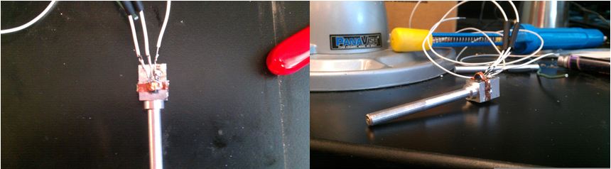
Figure 3. Old solid aluminum rod probe.
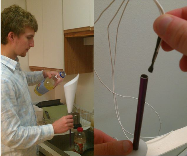
Figure 4. Building the temperature probes.
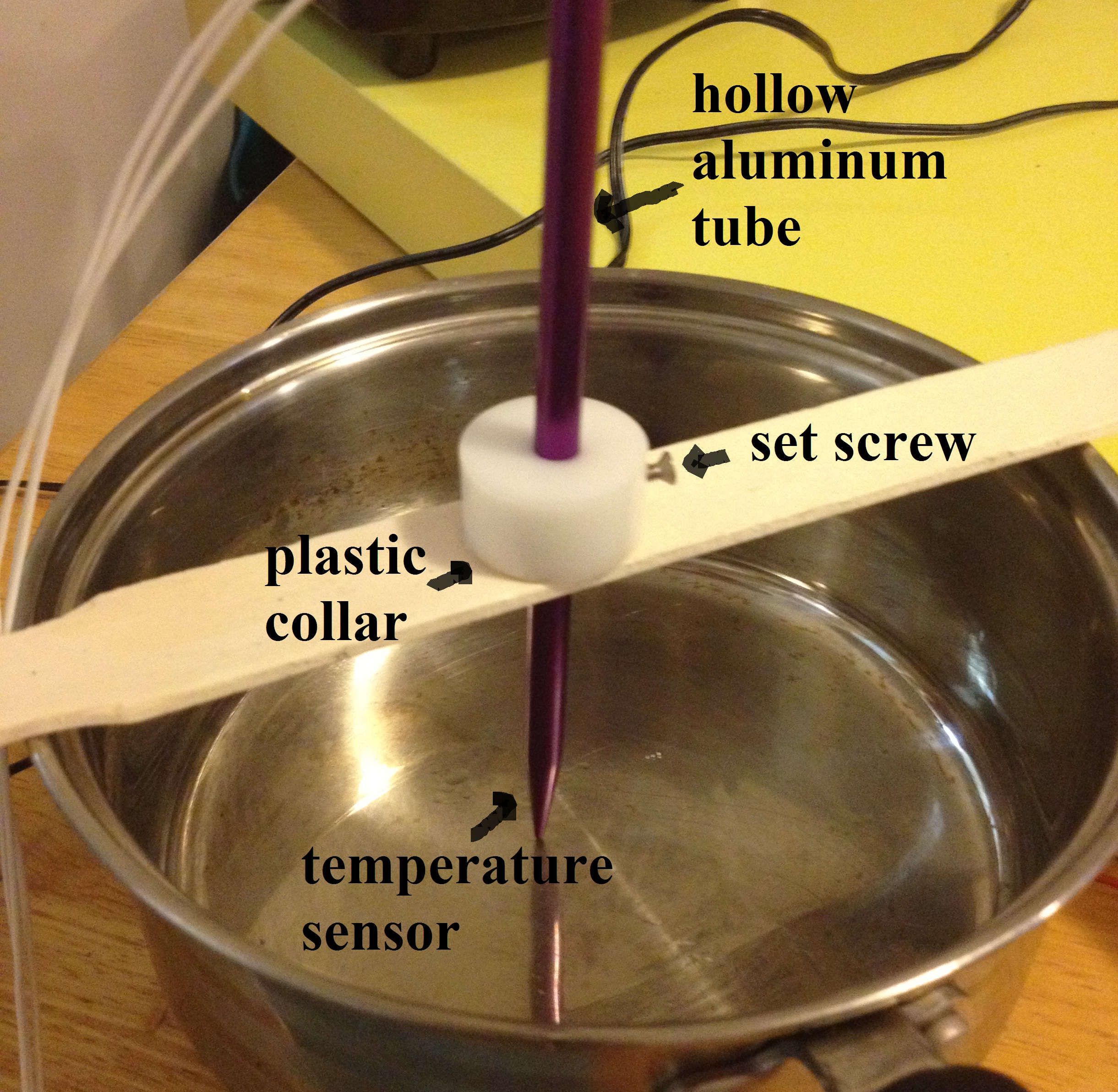
Figure 5. Complete probe with an attachment.
Measuring Circuit
The main purpose of the measuring circuit is to condition the analog signals coming from the temperature probes so that can be accurately measured by the MCU ADCs. The circuit was built on a separate board providing a certain level of isolation of the supply and signal lines from the rest of the project circuitry.
Because the IC sensor already provides a linear output that is in the input range of the ADCs, the only circuit elements between the probe output and ADC input is a low pass filter to get rid of higher frequency noise.
However, the NTC sensor circuit requires a little more circuitry in order to amend for its non-linear behavior at higher temperatures. First of all, in order to measure the resistance of the sensor, the sensor is attached to a series resistor (Rs) pulled Vcc high on one end and grounded on the other, creating a voltage divider. The selection of Rs was based on several factors. If Rs is too small, the NTC will dissipate too much power, which may cause damage or cause a self-heating bias in the temperature measurement. However, large values of Rs will cause very small voltages across the NTC. We selected 5kOhms for the series resistor as this limits power dissipation in the NTC to 12mW, safely below the limit of 50mW specified in the datasheet.
The voltage across the thermistor can then be read by an ADC and recalculated to find the temperature. However, because the signal is very low at high temperatures, we decided to amplify it with a non-inverting op-amp circuit. We considered three requirements for the signal conditioning circuit that takes the voltage across the NTC and makes it readable by the ADC of the ATMega.
- Operate in NTC temperature range of 15C to 200C.
- Voltage must be in the range [0.5V, 4.5V]. Outside of this range, the assumption of ADC linearity is invalidated.
- The change in voltage for a 0.5K change in temperature must exceed the resolution of an 8-bit ADC with 5V reference (i.e., about 20mV)
Using these requirements, we chose four software-selectable gains for a non-inverting amplifier circuit. Without any gain, we saw that the resolution requirement is only satisfied in a narrow temperature range. We then calculated the minimum gain to meet the resolution specific for each temperature. Next, we calculated the output voltage with the minimum gain, seeing that it is in the required range for all the temperatures we need. This demonstrates a solution is possible if we can have numerous selectable gains. The next step was to choose gains for different temperature regions that meet the requirements. We chose five gain regions and tweaked them until they met spec. Finally, we calculated the value of the feedback resistors to achieve these gains, and then slightly changed the gains to produce resistor values available for purchase.
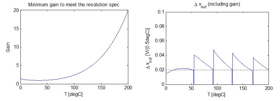
Figure 6. NTC circuit performance simulation
We decided to use MCP6231 op-amp that provides very high gain, good linearity, and rail-to-rail output range but is relatively cheap due to its low bandwidth (unnecessary in our design as the temperature fluctuations are near DC). We used a 20 kOhm feedback resistor and the following set of 5 selectable dividing resistors:
| Function/Mode | Actual Resistor Value (remeasured with a DMM) |
|---|---|
| Rs | 5.04 kOhms |
| Feedback Resistor | 20 kOhms |
| Gain: 21.2 | 990 |
| Gain: 11.15 | 1.97 kOhms |
| Gain: 4.824 | 5.23 kOhms |
| Gain: 2.1 | 18.17 kOhms |
| Gain: 1.1 | 100.2 kOhms |
The dividing resistors are selectable by pulling the single selected resistor low to create an op-amp circuit with gain set by that resistor value.
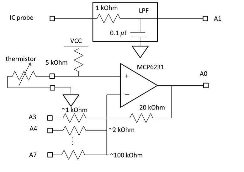
Figure 7. Measuring Board Schematic.
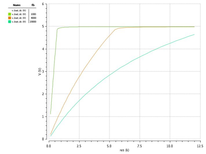
Figure 8. Measuring Circuit Cadence Simulation of DC sweep.
Hot Plate Interface
The stepper motor is used to turn the dial on the hot plate to a desired position with 7.5 degree steps. We wanted a simple interface between the motor and the dial that is easily removable to mitigate safety concerns and is universal to different types of stove dials. We found a scrap c-channel that when padded with foam held the dial tightly, but the hot plate can still be pulled off without damage at any time. Hot gluing the motor shaft to the channel resulted in a cheap, reliable, simple, and safe interface between the stepper motor and the hot plate dial.
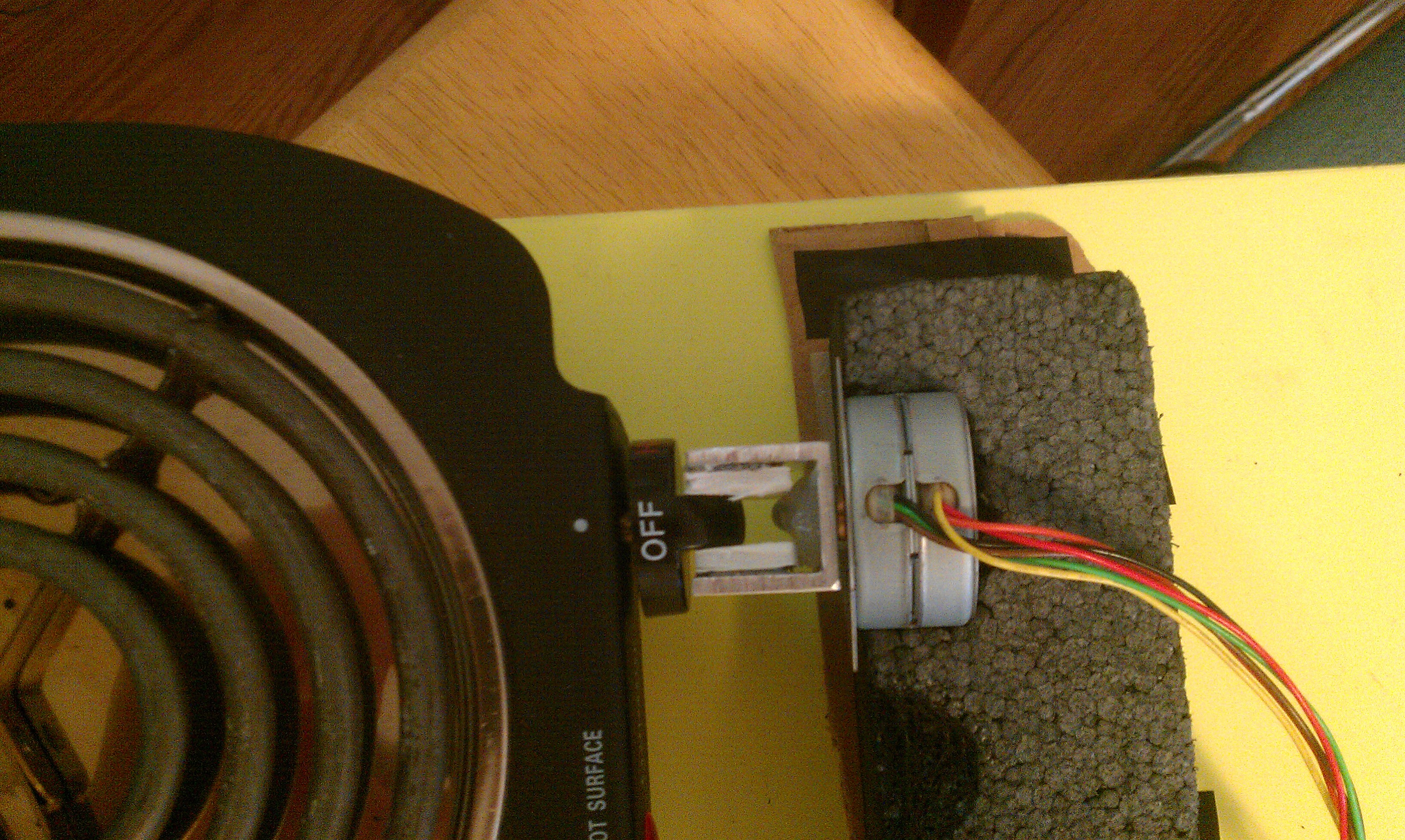
Figure 9. Stepper motor attached to the hot plate.
Stepper Motor Control Circuits
We decided to use a stepper motor because it has strong torque and accurate position setting that is need to turn/control the stove dial and because Andrew already had one in stock. Because it is a unipolar stepper motor, the control requires us to turn on, or generate a 12V drop across the particular coils at particular time in order to get a single step rotation. We used the following control diagram taken from the motor's datasheet to operate the motor with software:
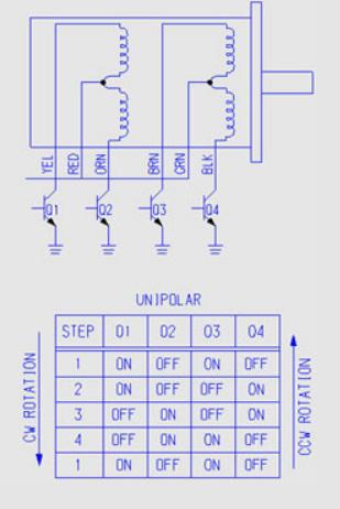
Figure 10. Unipolar stepper motor control circuitry.
The switches were implemented with a quadruple half-bridge IC, TI L293DNE, with outputs switching between 0 and 12 V, turning the coils on and off respectively by enabling a voltage drop across them. The outputs have to match their color-coded stepper motor wires in order to function properly with our code. The 4 half-bridge control inputs are routed to the MCU output pins that toggle the half-bridge states according to the stage diagram. The 12 V rail was powered with a separate power supply and we made sure that this rail did not feed anywhere else outside of this board.
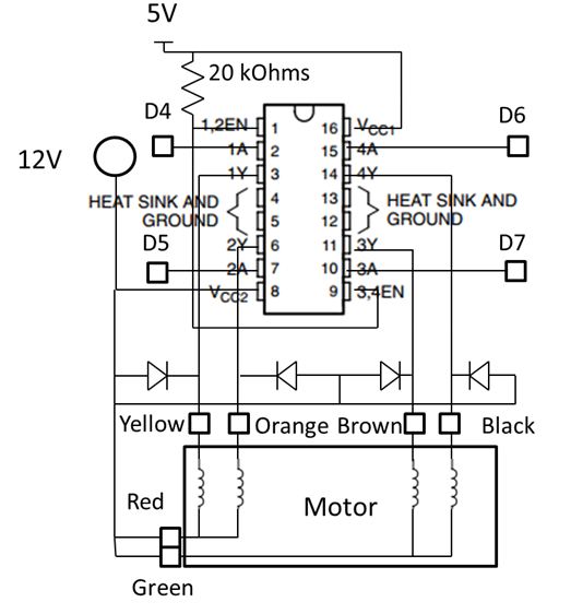
Figure 11. Stepper motor control board schematic.
Other peripherals
The other two electronic peripheral devices we used were the keypad and the LCD screen. The 4x4 keypad, hooked up to PORT B, allows the user to toggle between modes and enter numerical values. The LCD screen used in our setup has 4 lines of 20 characters per line and utilizes a standard Hitachi HD44780 Driver/Controller. We were fortunate that Adam already had one as its relatively large size gave us enough space to produce a more thorough output. The following table contains all the pin assignments for the keypad input and LCD output
| MCU | Peripheral |
|---|---|
| B0-B7 | Keypad pins 1-8 |
| GND | LCD Pin 1 |
| VCC | LCD Pin 2 |
| GND | -> 1 kOhm Resistor -> LCD Pin 3 (contrast input) |
| C0-C2, C4-C7 | LCD Pins 4-6, 11-14 |
Software top
Our program has five tasks:
- scanning the keypad for input
- updating the stepper motor
- measuring the temperature
- running the controller
- updating the LCD display
To drive the stepper motor, four I/O pins must be set to one of four stages, as documented by the motor datasheet. A few milliseconds are necessary for the current to ramp up in the motor coils, so a delay between state transitions is necessary. To avoid blocking program execution during the delays, a non-blocking stepper driver was written. To request the a change in motor position, the function setStepper is called with the current and desired motor positions. After bounds checking, this enables the stepper motor. Every 9 milliseconds, taskStepper() is called, which will advance a state machine if the motor is enabled. To ensure that motor coils are not left energized (which would draw excessive power), intermediary states are added when the . Using the stepper.h interface, this stepper motor driver can be easily used in future projects that need to control unipolar stepper motors to absolute positions (rather than spin rates).
The program has four basic modes that the user can choose to enter. The user interface is menu-driven through keypad input. The implementation can be found in userinterface.c, which both responds to the keypad input and updates the LCD display.
Calibration mode:
The hot plate dial has three key positions that must be calibrated so that the program knows how far to turn the dial to achieve maximum and minimum settings. A procedure is done by the user in calibration mode. The results are saved in EEPROM so a cooking device only needs to be calibrated once. First, the user is asked to move the dial to "OFF". Then the user presses keys to increase the setting until it reaches the minimum setting at which the hot plate is on. (There is a rather large region near "OFF" in which the hot plate is completely off.). Then the user presses keys to increase the setting until it reaches the maximum settings. Once the calibration is complete, the stepper returns to the "OFF" position, and the results are saved.
DC heat mode:
This mode is a slight modification of how cooking device dials are typically used. Using keys, the user can increase or decrease the heat manually, with the result displayed as a bar graph on the LCD display. When entering DC heat mode, the user can set a timer in minutes and seconds. The timer is displayed on the LCD and when the time expires, the cooker will automatically be turned off. DC heat mode makes two slight improvements over typical operation of a stovetop dial and kitchen dial. First, the automatic turn-off at the expiration of the timer has a lower risk of burning the food since the user does not need to not responding to a kitchen timer immediately. Second, the electronic interface could be beneficial for users with disabilities if the user interface is redesigned to accommodate specific needs.
Autotemp mode:
In this mode, the user enters a desired temperature in degrees Fahrenheit or Celsius and the controller will attempt to bring the object to that temperature and keep it at the temperature indefinitely.
Autocook mode:
There are three preset cooking routines in autocook mode to allow automatic cooking of different items. The presets determine the desired temperature, maximum heat input (to prevent burning), and time to stay at the desired temperature before turning off. The preset used are as follows:
- Green Tea: 68 C (154.4 F) for 2 minutes
- Medium Beef: 62 C (143.6 F), stop immediately when temperature is reached and never exceed 75% of the maximum setting to avoid burning
- Soft-Boiled Eggs: 63 C (145.4 F) for 45 minutes
Output calculation was done as a ratio of the maximum heat input. Based on a 1.1kW peak electrical power rating of our hot plate, we assumed the maximum heat input to be 750W. By modifying the QMAX symbol, the controller should scale properly. Output calculation also took into account the point at which the dial turns on. On our hot plate, the device is not on between "OFF" and "LOW." Therefore, we needed to add an offset to the controller output based on the latest calibration result of the minimum on state of the hot plate.
Gain tuning was done in the Matlab simulation since experiments are very time-consuming in slow thermal systems. Our final gains were:
kp = 15, ki = 0.15, kd = 15
Results top
The cooking assistant design is responsive. Since the device must wait for heat transfer to take place, the process is very slow. The relatively low measurement and control rates were intentional in the design and do not affect performance as they are must faster than the rate of change of the thermal systems.
When the system is in thermal equilibrium, the temperature measurement is very accurate, with errors less than 1 degree C. During the heating of water, the probe usually lagged behind by 2 degrees due to the time necessary for heat transfer. (Accuracy was found by comparison to a high-performance commercial thermocouple system.)
Figure 10 shows the results of the first full cooking test we did. In this test we used the green tea autocook mode. The measured temperature (using the IC probe), the temperature from the thermocouple reader, and the predicted time response of the system in the Matlab control system simulation are all plotted.
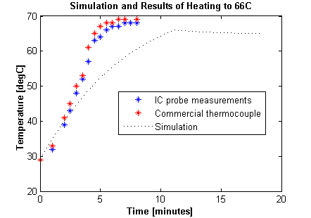
Figure 12. Simulation and results of heating water to 66 C.
The IC probe shows great performance with negligible steady-state error and acceptable lag during heating. The control simulation software was an acceptable match to the results as we only expected the simulation to be very approximate and give us order of magnitude information.
In software, we designed for safety by including a warning screen and making a press of the star button on the keypad executed a safety stop, regardless of the mode. In the safety stop, the dial is turned "OFF" assuming it is in the worst-case (i.e., highest) setting. We also designed a simply detachable interface with the hot plate so one can easily and immediately disconnect the device completely if needed. By using the dial interface, we were able to not open up the cooking device and alter the approved device. The temperature probes were designed so that aluminum is the only material to touch food. The oil used for thermal conduction was food-grade soybean oil, so a leak is not expected to have adverse health and safety effects. However, this is not sufficient to claim that food cooked by our project is safe for consumption.
Due to the menus on the LCD display and the use of keypad input, the project is very easy to use. By changing the user interface, it is possible that the project could allow people with certain disabilities to use a cooking device more easily through a specially-designed electronics interface.
Conclusion top
Overall, we were pleased with the results of our project. We were able to achieve desired temperature during shorter cooking operations. For longer operations, such as slowly cooking the beef, some undesirable aspects of our hot plate interfered with the cooking. From experimentation, we found the hot plate has a thermostat that changes the minimum on position with temperature. This result affects the assumption that heat input is determined by dial position. Our device was able to operate fine despite this undesirable dependency in many scenarios, but not when cooking meat.
From the start, we thought the performance would be much better if an automatic control system was built into an electric stovetop. With an integrated device, the control would have better performance as there would be fewer assumptions about the cooking system. However, an aftermarket addition was safer, easier, and applicable to many of the existing electric stovetops.
Goals
| Accurately measure temperature of various food items including water and meat: | yes |
| Control a hot plate using a motor: | yes |
| Automatically heat water for tea: | yes |
| Automatically cook soft-boiled eggs: | yes |
| Automatically cook a steak: | no |
Applicable Standards
There were not any applicable standards for our project.
Intellectual Property
We used two software libraries (lcd_lib.c, uart.c) which are properly referenced. We also used keypad scanning code and ADC demo from Bruce Land. All aspects of the source code are either properly cited or original. No sample parts were used. Through minimal research, we've found various patents for temperature-controlled cooking devices. Our design is original and does not use material from the existing, patented designs; however, it is unlikely to be possible to acquire a patent given the broad applicability of existing patents.
Ethical Considerations
The development and outcome of our project are consistent with the IEEE Code of Ethics. Neither our actions or our work brings up any ethical violations or concerns. In line with the Code, we both designed our project for safe operation and disclosed all safety concerns relating to our project. Safety-minded design and communication of dangers to the user ensure the project does not hinder the welfare, health, and safety of the public. We identified a few safety concerns and designed the system to mitigate the concerns where possible. If the automatic control behaves in an undesirable manner, the user must be able to immediately stop control. This requirement was satisfied in both software and hardware. At any time, pressing the star key turns the dial to the "OFF" position assuming the dial is in the worst-case position (maximum on). The system does not clamp onto the dial and can be pulled off immediately in case of emergency. There is the possibility that the system is misused for completely unattended cooking, which is dangerous. A commercial product should have additional capability to detect dangerous scenarios and clearly communicate to the user that completely unattended cooking is dangerous.
Our performance claims are based on fair data and are reasonable and realistic. We offered assistance to other groups when appropriate and received help and criticism from other groups. Many ideas were contributed by others for our project and these individuals have been referenced for due credit. Some external source code was used and is referenced properly.
Legal Considerations
There are not any applicable legal restrictions. Our project interacts with the hot plate in a manner consistent with its normal operation and uses approved power supplies. We don't use transmitters or any device that may interfere with others.
Appendices top
Source code
- Source code is available here: Source.zip
- MATLAB simulation code: matlab.zip
Schematics
Refer to the hardware section for all the schematics
Budget
| PART | SOURCE | QUANTITY | UNIT COST | TOTAL COST |
|---|---|---|---|---|
| Grand Total | $60.08 | |||
| ATMega644 MCU | Lab | 1 | $6.00 | $6.00 |
| Target board | Lab | 1 | $4.00 | $4.00 |
| 12VCD power supply (1) | Lab | 1 | $5.00 | $5.00 |
| 12VCD power supply (2) | Owned | 1 | $0.00 | $0.00 |
| breadboard (small) | Lab | 2 | $1.00 | $2.00 |
| Stepper motor (Portescap 42M048C2U) | Owned | 1 | $0.00 | $0.00 |
| Quad half-bridge (TI L293DNE) | Digi-key | 1 | $2.17 | $2.17 |
| Bulk Capacitor (Kemet ESK107M025AE3AA) | Digi-key/td> | 1 | $0.18 | $0.18 |
| Resistors, diodes, and small capacitors | Lab | N/A | 0 | 0 |
| NTC Thermistor (EPCOS B57560G0103F000) | Digi-key | 1 | $3.15 | $3.15 |
| AD22100STZ Temperature sensor | Digi-key | 1 | $6.69 | $6.69 |
| Electric Burner | Amazon | 1 | $14.51 | $14.51 |
| Keypad | Lab | 1 | $6.00 | $6.00 |
| 4x20 LCD Display | Owned | 1 | $0.00 | $0.00 |
| Op-amp (MCP6231-E/P) | Digi-key | 1 | $0.38 | $0.38 |
| Header pins/sockets | Lab | 120 | $0.05 | $6.00 |
| Aluminum knitting needles | Michaels | 2 | $2.00 | $4.00 |
| Plastic collar | Scrap | 1 | $0.00 | $0.00 |
| Black Foam | Scrap | 1 | $0.00 | $0.00 |
| Foam board | Scrap | 1 | $0.00 | $0.00 |
| Aluminum C-channel | Scrap | 1 | $0.00 | $0.00 |
| 4-40 Screw | Scrap | 1 | $0.00 | $0.00 |
| Paint Stirrer | Scrap | 1 | $0.00 | $0.00 |
| Wooden table top | Scrap | 1 | $0.00 | $0.00 |
Task Division
| Mechanical and thermal hardware: | both |
| Circuit design/debugging: | both |
| Circuit and harness building: | Adam |
| Software design: | Andrew |
| Software debugging: | both |
| Control simulation: | Andrew |
| Website content: | Both |
| Website layout: | Adam |
References top
This section provides links to external reference documents, code, and websites used throughout the project.
Datasheets
- ATmega644
- Quadriple Half-H Bridges
- Op-Amp
- Stepper Motor
- Analog output voltage temperature sensor
- NTC
Referenced Code
- Keypad Scanning Code
- UART Library written by Joerg Wunsch and modified by Bruce Land.
- LCD Library from © 2007 Scienprog.com
Cooking Modes References
Acknowledgments top
Thanks to Chris Jewison, Rob Moore, and Sammy Nowierski for both ideas and assistance with mechanical and thermal aspects of the project.
Also thanks to Bruce Land and the ECE 4760 TA's, Joe and Pavel, for helping us with various bugs and problems throughout the semester