
CMR Robot Arm
ECE 4760 Final Project ReportCaroline Chang, cc722
Scott Warren, spw54
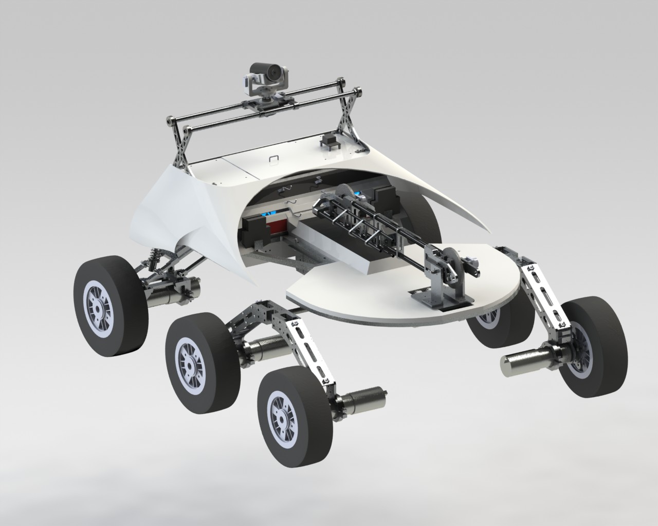
Our project was mainly designed for the Cornell Mars Rover project team (CMR), which will be using the robotic arm for competition to complete many different tasks in the deserts of Southern Utah.
For our ECE 4760 final project, we created the control systems for a robot arm that is able to use three different end attachments to perform a variety of specified actions, include pushing buttons, scooping up dirt or other items, picking things up with a hook, flicking switches, and taking voltage readings for solar panels. This robot arm uses the Arduino Mega2560 to take in commands from a user to determine which position to move to and what actions the arm needs to perform. It uses four different servo motors to control the four degrees of freedom over the wrist, elbow, and shoulder joints. Also, it controls three end attachments that are attached at the end of the arm: the hook, the scoop, and the control panel interface (CPI). Our controls are also able to open and close the scoop’s lid servo and turn on and off the brush of the CPI, which has two probes attached that takes the voltage readings.
Cornell Mars Rover
Robot Arm
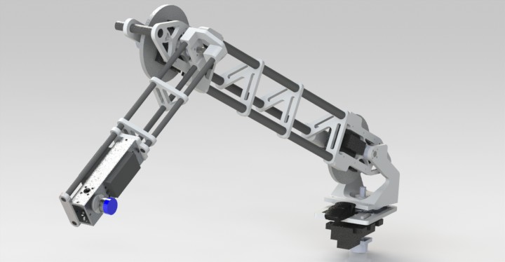
Table of Contents
High Level Design Back
Rationale and Sources Back
The leader of the CMR control systems team was seeking for recruits that can work on the robot arm to their rover. Because of our ECE background and our experience with PID and motors from lab 4, we decided that it was very appropriate to take on this task and that it would be perfect for our final project. The basic requirements and functionalities of the arm had already been set by the leaders prior to us joining the team, but we were constantly revising and changing the way some parts worked based on what we thought was most appropriate in implementing those requirements.
Background Math Back
The inverse kinematics and all the set torque and gear ratios were the tasks of other members on the Mars Rover team. We were in charge of mainly controlling the arm by using the PID mathematic feedback mechanism. The PID mechanism is a control loop that calculates the error between where the ‘variable’ is currently at and where it is supposed to be,its goal. It requires three correcting terms to calculate this error, the proportional gain, the integral gain, and the derivative gain. These three terms are summed together to calculate the PID’s output, as shown below in the two figures.
Figure: PID Block Diagram
Figure: PID Equation
Logical Structure Back
Hardware
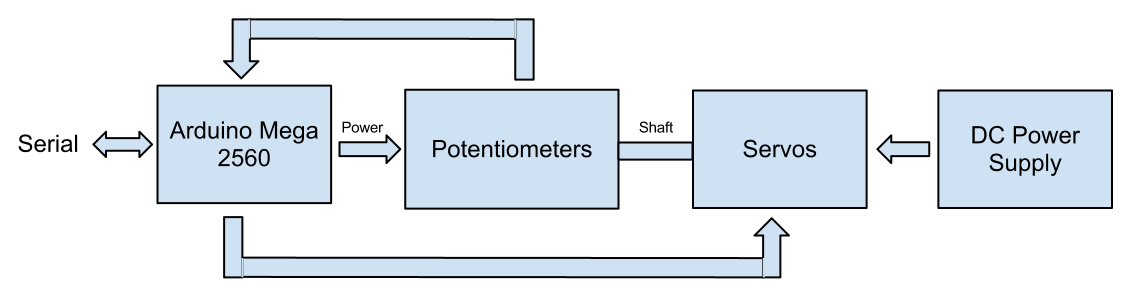
Figure: High Level Hardware Structure
The hardware operates in a way that when you receive a serial input that tells the arduino to perform a certain task, the MCU would read the inputs and parse the commands, and then send it to the servo, which is connected to a potentiometer to determine its angular position. The servos are powered by an external DC power supply.
Software
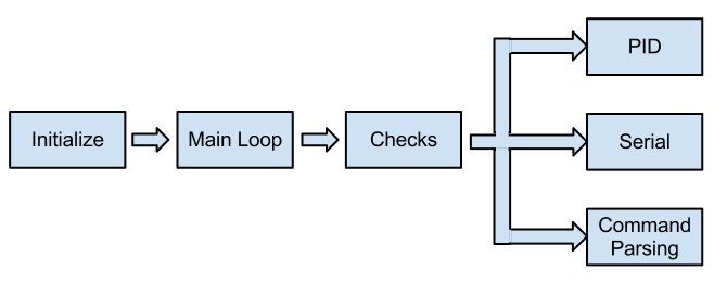
Figure: High Level Software Structure
There were three main functions that our software had to accomplish: run PID, get the serial inputs, and parse the commands. These all ran at different times, depending on whether it had reached the specified time to run the PID, if it received a serial input, and if a new command needed to be parsed after the goal was reached. It constantly ran these functionalities in a loop so that whenever the servos need to move to a new position, it would be able to do so.
Hardware & Software Tradeoffs Back
For hardware, we could have gotten cheaper servos that would be able to withhold the weight of the arm. However, because all the materials were funded by the project team, the extra torque was necessary so that we can make sure that no matter how much load needs to be picked up, the servos would hold. They were expensive, but they were also one of the better ones you will find out there. For software, we had the choice between coding in the Arduino IDE or C. Instead of programming in only one and not being able to experience the pros and cons of each one, we decided to do both and make a comparison between the two, in terms of their efficiencies and their execution speed.
Standards & Existing Patents and Trademarks Back
Our robot arm is closely related to a few available standards because it is implemented with serial communication and several motors. Serial communication is made between the main board, which sends the commands, and the Arduino, which receives and parses those commands. This follows the RS-232 communication standard. Also, the use of multiple motors follows the IEEE AC Motor Protection Standard because it allowed us to have all the necessary functions for adequate protection of our motors based on type, size, and application.
The robot arm is a common robotic component that is implemented in many different devices, and there are already many patents released. The very first idea of a robotic arm was patented in 1961 by George C. Devol, who engineered a mechanical arm that can perform simple tasks like lifting and grasping. Many other modern robotic arms with more joints and range of motions were designed based off of Devol’s innovation. However, what makes ours unique is its integration to the rest of the rover and the different functionalities that it has to be able to perform.
Hardware Design Back
Figure: Entire Schematic
Arduino Mega 2560 Back
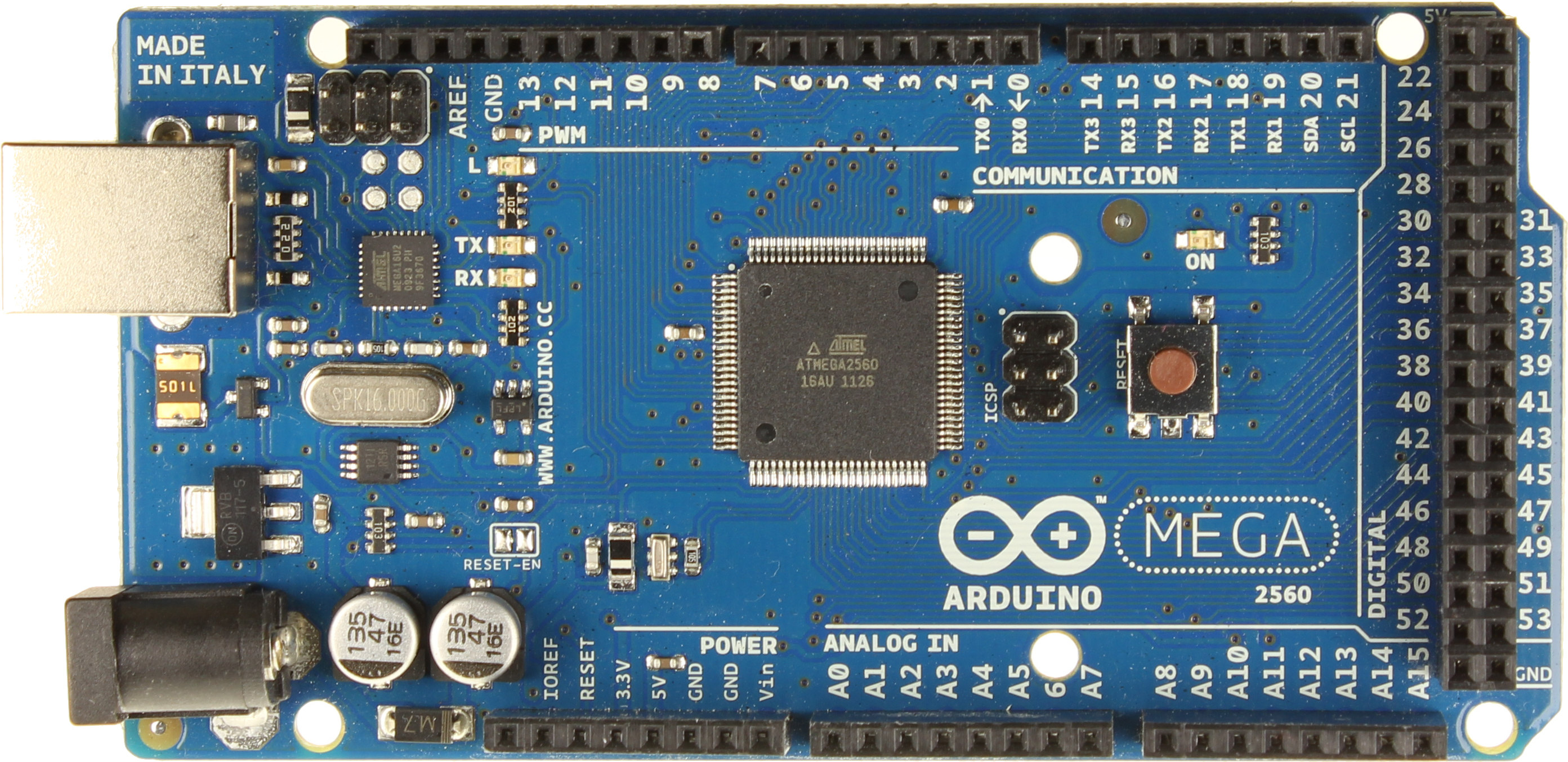
Figure: Arduino Mega 2560
This Arduino microcontroller provided the control signals and received inputs to make the whole system work. It was used to interface between the Serial and the rest of our hardware, using both our Arduino IDE code and our C code. It supplied power to the potentiometers and read in their values, as well as generate the PWM signal to control each of the servos. It also determined when to compute the PID for the different motors, using protocols that are explained in the ‘Software Design’ section. The base servo was connected to Pin2 on the ‘PWM’ output ports of the Arduino, the shoulder servo to Pin3, the elbow servo to Pin5, and lastly, the wrist servo to Pin6. For the end attachments, the scoop servo is connected to Pin7 and the CPI brush motor is connected to Pin10. These Pin numbers for the PWM outputs change for our C code. However, for both codes, their corresponding analog inputs of the potentiometers were connected to the same corresponding pin numbers on the ‘Analog In’ ports of the Arduino.
Servos Back
Figure: Servo
A servo in general is controlled by a PWM wave. Most, including the ones we used, take a 50 Hz 0-5V signal, making them easily controllable by microcontrollers. The neutral position is 1500 us. This corresponds to either a specific rotation in the case of a non-continuous servo or no rotation in the case of a continuous one. Changes to the pulse width away from 1500 causes the servo to move to a new location, non-continuous, or begin turning one way or the other, continuous.
Base Servo - The base servo we were given to use was an old worn out one. We found out through testing that the amount the PWM had to change to move the servo was a lot higher than the brand new servos, and it was different in each direction. We tested it and found out the minimum change in pulse width, going both ways, from neutral that would make it spin. Then we set neutral to be the average of the two. Because we needed such a big change, the proportional term in our base PID calculations needed to be much larger than the other joints.
Elbow & Shoulder Servo - The elbow and shoulder share the same configuration of servos. They’re both high torque servos with large gear ratios. The shoulder joint needs the most torque because it lifts the entire arm. Both of them are continuous, so similar to the base, they need to be controlled with PID. These servos were modified to be continuous by the company they were ordered from. They came with their internal potentiometers exposed. We needed to tune these potentiometers so that a pulse width of 1500 us would mean the servo wasn’t moving. After tuning both of them, we simply super glued the potentiometer tuner so that it would stay at that position.
Wrist Servo - The wrist servo was different from the elbow and shoulder servos because it didn’t need to be continuous. Three and a half turns of the servo was enough to get the wrist to go through its full motion. The gear ratio was lower than that of the elbow and shoulder.
Potentiometer Back
Figure: Potentiometer
The potentiometers were used to determine the position of the base, shoulder, and elbow joints. It gave back to the microcontroller a voltage feedback that was relative to the rotation. The ground and power lines are connected to the Arduino’s ground and Vcc. The wiper connections go into the arduino’s analog input pins. As the joint rotates, the voltage changes linearly with the rotation. This allows us to know at what angle the joint is at and lets our PID code determine the correct direction and speed to move the servo at.
DC Power Supply Back
We used a DC Power Supply to provide 5 Volts of power to the servos. In the actual rover this will come from the batteries. The grounds of both the DC power supply and the arduino were referenced together so that the pulse width was correctly within the range the servo was expecting.
Software Design Back
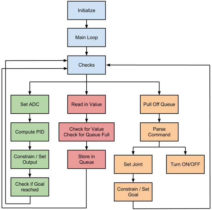
Figure: Entire State Machine
Arduino Code Back
We started by using the Arduino IDE with all the included Arduino libraries, but we did not end up using this version. However, it was kept up to date so that we could make a comparison between this code and the C code.
Initialization
The setup function in arduino only runs once. All of our initializations happened here. We set the setpoints the base, shoulder, and elbow to their corresponding starting values, and we set the wrist and scoop servo outputs as well. The, the PID sample time, the output limits, and the mode were all set. The mode is what turns on the PID computations. All of the input, output, and setpoint variables were linked in the variable declaration. The servos were then set with the appropriate pins. This just tells the servo object where it should output the PWM wave to. We set our goal flag to false and initialized the serial communication.
Main Loop
We read in all the input values and ran PID for each of the joints it was needed on, the base, shoulder, and elbow. After the output values are obtained, not necessarily changed from last PID compute function call, they are written to the servo objects. Then, we checked for the goal reached condition of the errors being zero. Even though inputs and setpoints were double values, which is what the PID library expects, we could do this because analogRead returns an int, and we’re setting the setpoints to ints so that condition can easily be met.
Arduino has a serial buffer so we checked this to see if it had received two bytes. If it had, then we checked the queue count to make sure it wasn’t over our limit. If it was, an error message was sent over serial. If the queue still had room, which should almost always be the case because we set the max to 255, then we read in both bytes and shifted the first to the high byte of the int. The received command was then checked for validity. We expected bits 14, 13, and 12 to be 0. If they weren’t we threw it away. If they were we stored the command on the queue.
The parsing of the commands would then take place as long as there was a command on the queue and the goal had been reached. The command is popped off the queue and the most significant bit is checked. If it is a one, we turn the motor on and close the scoop. Only one of these will actually be attached at a time. If the most significant bit is 0, we then parse the command to determine which joint it is for. The data bits are parsed out and the appropriate joint’s setpoint/output is set after being constrained. The goal reached flag was also reset.
C Code Back
We used three different timers in our code, so we started by first setting up all three. The first, timer 0, was set for CTC mode counting to 15, with a prescaler of 1024. We used this timer to time our PID control. Each PID loop runs about every 1 ms, which is a lot faster than what we actually need, but we decided to run it very fast to reduce the delay between starting an ADC conversion and reading it in. The ADC conversions are started in one PID loop and read in the next. There was also nothing preventing us from running it that fast. Timers 3 and 4 were used to generate the PWM signals for the servos. Both were set to the phase and frequency correct mode with the OCnX output being clear on the up count and set on the down count so that we could directly control the pulse width by setting the appropriate OCRnX register. We divided both by 8 because the 16-bit timers wouldn’t be able to count as high as we needed if there were no prescalers. A higher prescaler wasn’t used because we wouldn’t be able to get as high of a resolution. ICRn registers are set to 20,000 to make the PWM signal be 50 Hz. (16 M / 8 / (20000*2) = 50Hz) 20,000 was multiplied by 2 because the timer counts up to that value and then back down. The associated pins were made outputs.
We initialized the ADC by setting the ADEN bit and setting the prescaler to 128. A base input conversion was also started right away by setting the appropriate ADMUX bits and the ADSC bit. Since the base PID loop was entered immediately, we also decided to wait for that first conversion to finish by checking the ADSC bit before continuing. The UART got initialized by setting U2X0 to double the transfer rate. TXEN and RXEN bits were also set to enable transmission and receive. The baud rate was selected to be 9600.
Before entering the main loop, we did a few last variable initializations. The goals were all set to their appropriate start values, the goal flag was set to null, and the queue indices were zeroed. The queue is just an array of integers. We kept a head and tail index on the queue to allow us to do one line enqueues and dequeues. The queue is 256 integers large, and our indices are chars so we don’t need to roll them over ourselves.
Main Loop
PID:
There are three PID sections, one for each of the base, the shoulder, and the elbow. We decided to interleave these for a few reasons. The main one was so that we wouldn’t have to wait for an ADC conversion to complete. We could just start the conversion at the end of one PID and read it in at the beginning of the other. This works because the minimum time between each of the different PID sections is more than the required time for an ADC conversion to finish. The time it takes to do an ADC conversion is 13 ADC clock cycles, so with our prescaler of 128 comes out to about .1 ms. This is over 3 times less than the time between PID’s, which is 1ms/3.
The PID sections themselves were all very similar. They read in the input from the ADC, which was 10 bits, and used that to calculate the error from the goal. This error was then summed to get the integral term. The output was then calculated using the defined P,I, and D terms. This output was then constrained to be within the bounds that we had defined. The output bounds determine the max speed the servos can reach. Once the output is within the bounds, we would write to the appropriate OCRnX register after shifting by 1500 to change the pulse width accordingly.
At the end of the PID section we set the ADC up for the next joint’s conversion, and we would start it. A variable is also set so we can guarantee that joint’s PID will be the one reading in the conversion. This variable also prevents the same PID from being run again as the time it takes to run through the main loop is less than the amount of cycles for one count of timer 0. There is also a check done to see if the goal was reached. Our condition for that is if all of the error terms are 0, then the goal has been reached. This is attainable as we’re using integers for calculation and not floating point.
Serial Communication:
he Serial works by checking the serial buffer. If the receive bit is set, then we know there’s something in the buffer. First, we checked to make sure our queue isn’t full. If it is, we would send an error message back over serial by waiting for the TX buffer to clear, and then write a single error char to the TX buffer. In this case, the received byte is not read and stays in the receive buffer. The error message, ‘Q’, will then be sent every time a command is trying to be enqueued into the queue when it is full. Whenever the ‘Q’ is sent, it drops the command entirely, so the user would have to resend it when the queue is no longer full.
When the queue isn’t full, which should always be the case assuming the sender doesn’t send way too much data, we would move on and read in the received byte. The first time a byte is received, it is read and stored in a temporary variable. This was then the high byte of the int, so it was moved to the high byte of the temporary variable. Then, a flag was set saying the high byte has been received.
When the next byte is received it is moved into the lower byte of the temporary variable. This is then checked for validity. If bits 14, 13, and 12 are not 0, then the command we received isn’t of the appropriate form. In that case, the received data is thrown away and a bad value error, ‘V’, is sent back over serial. If the command passes, then it is put onto the queue. The flag is then reset so that the next integer can be received the same way.
Parse Commands:
Figure: Protocol for Parsing a Command
Parsing was done whenever there is a command waiting in the queue and the current goal had been reached. When that happens, the command was dequeued and parsed. First the most significant bit is checked. This determines whether the command is for an end attachment or a joint. End attachment commands simply have the least significant bit either set or not in order to tell the device whether the end attachment should be turned on/off or opened/closed.
The joint command is a little more complicated. Bits 11 and 10 contains the information for which joint the command is for. These get checked, and the command parsing moves on to the appropriate joint. The data bits, which are 10 of the command, are then parsed out and set as that joint’s goal. In the case of the wrist, there was no goal set point because PID is not necessary, so it is just the output of the servo. This goal/output is constrained and the goal flag is reset before exiting the parsing section.
Macros:
We wrote a few macros in our C code to make the code look a little cleaner. ABS was just a absolute value macro that compared a number to 0 and returned the number if it was greater than 0 or returned the negative version of the number if it was less than 0.
The other macros were for our queue implementation. In order to add something to the queue, ENQUEUE, we simply needed to put that value into the queue array at the tail index and increment the tail index. To remove something from the queue, DEQUEUE, all we had to do was return the value of the integer in the queue array at the head index and increment the head index. Because we chose our queue to be an array of 256 integers, our indices wrap around by themselves because they are unsigned characters.
Testing Back
Servos:
We had no knowledge of how servos worked before we started working on this project. First, we read up a bit on how they work. This was followed by some testing with simple arduino code. We wrote some basic code that was adapted from the servo library, which generated a PWM signal. This signal was controlled by serial input of characters, ‘m’ as 1500us, ‘a’ as 1200us, and ‘z’ as 1800us. This allowed us to see the range of motion of the servo and see which direction a certain pulse width would move the servo. We did this to confirm our assumptions about how a servo works.
In the code for each servo, there are a few constraints to prevent them from doing unwanted things. Each PID calculation is constrained to be within some range, which limits the speed each of the continuous servos can move in either direction. These also had their goals constrained to be within some range. The non-continuous servos were just constrained as to their outputs.
Queue:
The queue on Arduino was very easy to implement and didn’t require much testing at all. Because of the way we implemented the queue in C, there were a few things we needed to test. We made sure the queue’s indices were behaving as expected as integers were put on and pulled off the queue. We also checked to make sure the indices overflowed as expected as that was a key part of our queue implementation. Later in testing when we had the serial working, we also tested the queue overflow condition by repeatedly sending valid commands.
Serial:
Testing for serial was done by sending characters through a terminal. We couldn’t find a good way to directly send the integer command we wanted, so we had to resort to some hacks. At first we just read in a character between ‘a’ and ‘z’ and converted that into an output for a specific joint servo.
When we had the rest of the code written, we started integrating serial more into how the final design would work. Instead of converting a character directly into a position, we would input two characters at a time which would be translated as an integer command. In order for us to do this, we had to figure out a way for characters to translate into valid commands. The hack we came up with was to shift each input character by 109, wrapping between 0-255. This meant “wm” = 119,109 became 10,0 = 0x0A00. This translated into a command for the elbow joint of 512. By changing ‘w’ to ‘x’ we could change the command to 768, which is still for the elbow. Going the other way was done with “vm”, making it an elbow command of 256. This allowed us to test the overall code receiving inputs almost like how we will actually receive them.
In order to more directly control the commands we send to the arduino, we programmed an STK500 to run a very simple program that would parse commands from a terminal and send the integer command into the arduino. This allowed us to run the exact code that we will be running when we integrate it into the rest of the rover. This is what was demoed.
Results Back
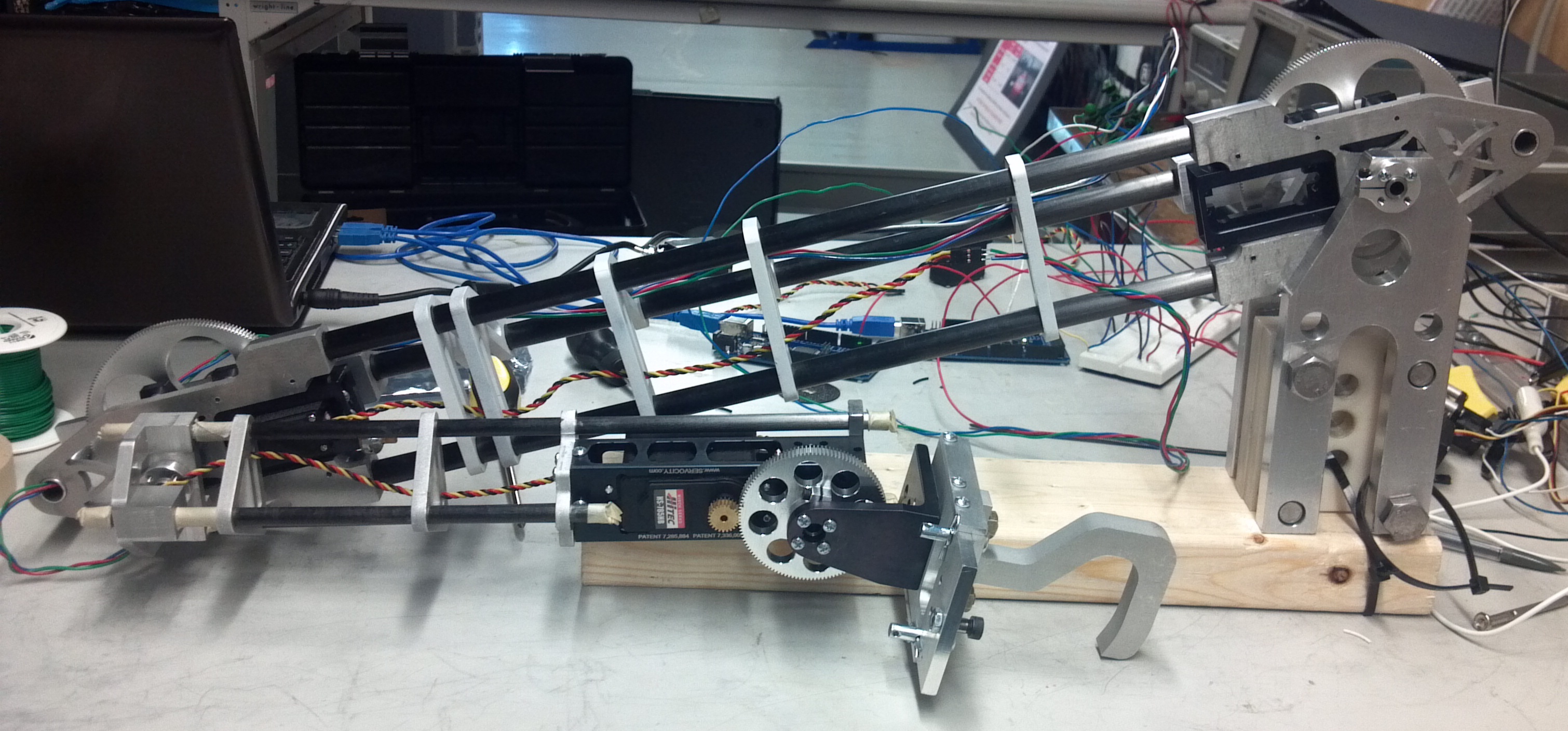
Figure: The Actual Robot Arm
Speed of Execution and Accuracy Back
Our code runs fast enough to handle a 9600 baud connection. The PID control also runs with minimal overshoot and jitter, at 100Hz, which is every 10ms. However, the response time was not critical for our application.
All our joints maneuvered to within a degree of precision. We tuned our PID parameters so that it would constantly correct the errors and act in a way so that all our values are about the same as their goals and setpoints. We constrained our outputs for each joint to the degrees that we thought were best for the different functionalities of the joints. For example, the wrist has 180 degrees of rotation, the elbow has 180 degrees, the shoulder has 90 degrees, and lastly, the base has 180 degrees.
Safety Back
Safety was enforced through multiple checks on the goal position being set, as well as the speed of the continuous servos. Throughout testing, to make sure that nothing dangerous happened, we always kept our hands on the power supply cord so that if something went wrong or if something unusual happened, we would disconnect it from the power supply and debug it from there. We also made sure that everything was clear of the extended length of the arm so that the sharp edges would not hit and harm anyone.
Arduino vs. C Comparison Back
After writing both in the Arduino IDE and in C, we saw a few differences. The Arduino code had many convenient libraries that we were able to use. The three main operations that we needed to accomplish to make the servos work were all already provided in the Arduino libraries, which included PID, serial communication, and queue implementation. There was also a simple analog read function that we used to get the potentiometer inputs.
For our C code, we basically tried to follow the same logical structure we did with the Arduino code. From the very beginning, we realized how much more efficient C would be comparatively. For starters, the Arduino creates a PWM using a timer, and through interrupts, it checks to see if a certain pin needs to be driven high or low. In C, we could just set up a timer to make a PWM purely through hardware.
Another optimization we made was to have the PID calculations done separately. This meant there was less time spent in the main loop while PID was running. It happened three times more often, but we felt that was a good tradeoff. We also utilized this interleaving of PID’s to optimize the ADC conversions. Instead of Arduino’s analogRead, which blocks the program until it can read in the conversion, we started a ADC conversion at the end of one PID calculation and read it in on the next. This implementation was ok because the minimum time between PID calculations was much longer than the actual ADC conversion.
Conclusion Back
We started our project with two main goals: To control the rotations of the shoulder, elbow, and wrist joints and the rotations of the base. And, to control the two end attachments by turning the scoop and CPI on and off. All the servos had enough torque to withstand the weight that they needed to hold for each corresponding part, which was what we were mainly worried about at the start of this project. However, the only difference in our project was that when we first started, we were given an Arudino to work with, and we were told to program using the Arudino IDE. However, after getting all the servos working using Arduino, we realized that it was way too abstract and high level for this purpose. We realized that it would be a lot faster and more efficient if this was written in the C programming language instead, which we ended up using as our main code.
For next time, we could have done a few things differently to integrate more functionalities for our robot arm. With the given servos, we could have made sure before all the testing and designing our software and hardware that the servos have much more torque than what it minimally requires to withstand the weight. This is because at some points, the entire arm was a little heavier than expected, which made it bounce slightly up and down, but it was very hard to notice. This would have helped a lot more with our accuracy. If we were able to add more to our project, we would definitely want to include unique characteristics that the arm could perform. For example, remembering certain tasks when commands are given to it so that it can replicate them in the future.
Our most important aspect of this device is to be able to receive the commands that are sent to tell the rover which joints to move and to which positions. It definitely conformed closely to the RS-232 communication standard because we send in a lot of information between the arduino and the serial, which is used to take place of the actual team member who will be sending the commands. Also, because of the use of multiple motors, it also conforms to the motor protection standard. It was our responsibility to follow these standards while creating our device.
Intellectual Property Considerations
We did not reuse someone else’s design or others’ code in writing ours, except some referencing to Bruce Land’s examples in lab on how to start the ADC conversion. Our project was created by the Mars Rover Team, and they had all the criterias and requirements decided on before we had started this project. Also, we did not reverse-engineer a design, and although there have already been robot arms patented, we did not match with their applications and capabilities. Ours had specifically three end attachments that the arm had to control. The robot arm is only a part of the Mars Rover, which means that the actual rover is not trademarked. We did not have to sign any non-disclosure form to get any sample parts. They were all provided by the team. In terms of patent and publishing opportunities for our project, we believe that this rover and robot arm is solely for competition because all the requirements and functionalities are based off the rules to the competition in Utah. Also, there are many devices in the world that are integrated like a rover or a robotic arm.
Ethical Considerations
Since our final project was for of the Cornell Mars Rover project team, our decisions and actions had to follow the IEEE Code of Ethics very closely. One of the code of ethics ensured that we were constantly thinking about safety and any health/welfare dangers that our project could bring. Working with many servos and sharp end attachments on our arm, we constantly made sure that there was no one within the range of our arm when it was fully extended. This way, none of the sharp edges can scratch or cut anyone. Whenever we lifted up the arm to test to servos, we made sure that if we dropped the entire arm, nothing would get hurt or damaged underneath. Furthermore, another ethic was to improve our understanding of technology and know what its applications and consequences are. For all our servos, we had made sure to include multiple checks that would constrain the output so that there won’t be anything potential errors in our functionalities. Also, we tried undertaking some of the technological tasks for other members after receiving trainings and learning from them. Because we did not receive machine shop training, we were not able to do the intensive machining. We were given a big responsibility to uphold for this project team because without a working and moving robot arm, the entire rover would not be able to go to competition and all the other members’ hard work would go to waste. We worked hard in not doing anything to affect the team’s reputation and made sure we made all the deadlines that they had asked for.
Legal Considerations
Our project does not have any legal considerations because every part of this device was designed and created by us and by the entire project team.
Appendices Back
Source Code Back
Schematics Back
Figure: Entire Hardware Schematic
Cost Details Back
All costs were covered by the Cornell Mars Rover Project Team.
Specific Tasks Back