"A smart piano that composes music of your own taste!" - sound bite
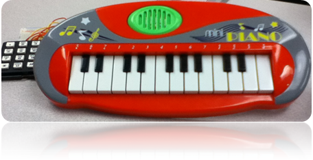
Figure 1: User interface of the project: a 23-key piano with a keypad.
Project Overview
We designed an electric piano that automatically composes a piece of music for the ECE 4760 final project. All the user need to do is to select a mood of the music and play two notes upon which the music is based, and then he can just lie down and enjoy the music created for him. He can also choose to train the piano by first playing several pieces of music he is fond of. The piano would then compose music based on the pattern of the music user just played.
High Level Design
Rationale and Inspiration
Composing has always been an almost forbidden area for people who have no systematic music trainings. Because of the complicated composing rules developed by different composers over the past hundreds of years, it could be a challenge for an amateur to create a piece of music that obeys most of the rules and thus sounds pleasant without multiple times of experimenting. Our project, "Auto-composing System", helps solve this problem by making composing easier for non-experts.
Our project features a very friendly user interface, which include an electric piano and a keypad. It needs almost no set up and can switch between different modes easily.
Inspired by the third lab in which we used FM synthesis to generate a sequence of sound, we developed algorithms to make the microcontroller (MCU) to not only generate random sequence of piano-like sound, but a piece of "real" music that sounds pleasant and obeys most of the composing rules.
Composing Algorithm Overview
Generally, our composing algorithm takes in three inputs and consists of three stages of composing. The first input that user has to enter is the mood of music that he/she wishes to create. Currently, we support two moods: happy and tender. The other two inputs are two notes chosen by the user.
In the first stage of composing, the tone of the music is determined as a result of the three inputs. Happy mood corresponds to a major tone determined by the two input notes, while tender mood corresponds to a minor tone determined by the two input notes. The speed of the music is also determined in the first stage by the mood input.
The next stage is to create the melody for the music. The first step is to set rhythm corresponding to different moods. After the rhythm is set, the next note of the melody is chosen roughly according to the corresponding Markov probability matrix until all notes of the melody is filled. We incorporate composing rules that cannot be represented by the probability matrix to the melody composing process by either setting certain notes deterministically or changing the probability matrix when choosing notes for some special rhythm.
After the melody is set, our algorithm chooses proper chord for it. The chord is chosen so that it sounds harmonic together with the melody and also varies with some randomness to avoid monotony.
There is a special train mode in our composing system that lets the user to build his or her own Markov probability matrix instead of using our pre-trained ones. If the user chooses to enter the train mode, the system allows the user to play a piece of music on the electric piano. Then the system will compute the Markov probability matrix based on the piece of music that the user played and thus could generate music that assemblies what the user just played with some variations.
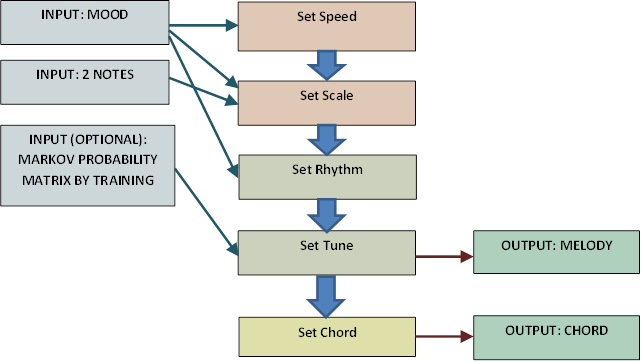
Figure 2: Composing Algorithm Block Diagram
Logical Structure
There are three primary components involved with the system: the input devices, the ATmega 644 MCU and sound output device.
The input devices consist of two parts: the piano input and the keypad. The piano consists of 23 keys ranging from G2 to F4 that user can play. The keys are divided into 3 sections and are treated as independent switches. Each section of the keys is connected to an 8-3 encoder to get four outputs that feed into the STK 500. The purpose of the keypad is for user to operate the composer. When the system starts, the user is supposed to first select a mood and whether he would like to train the piano by entering the corresponding keys from the keypad. If the user chooses to train the composer, he is also supposed to indicate he has finished training by pressing "0" button on the keypad. The user can also press the "*" button on the keypad to indicate he would like to stop the current music and restarts the process. Both the piano keys input and the keypad is debounced in software to avoid undesired inputs.
The ATmega 644 MCU is the "brain" of the auto-composing machine. It takes input from the keypad and piano and composes music catering to the user¡¯s preferences. Described in the composing algorithm above, the MCU identifies the key user presses and the notes user plays, and updates the melody, chord and rhythm by adjusting entries of the probability matrices. The MCU then synthesizes the corresponding piano sound using Direct Digital Synthesis (DDS) and Frequency Modulation (FM) synthesis with a 16 kHz sampling rate. The sound signal is fed into the output device through Timer 0 Pulse Width Modulation.
The output devices are fairly simple. An RC low-pass filter reduces the noises carried in the PWM output signal from the MCU and is connected to a speaker that generates the physical sound. A PUTTY terminal in the computer serves as the user interface to give proper instructions to user about how operate the composer.
High Level Block Diagram
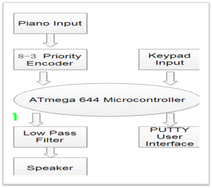
Figure 3: High Level Block Diagram
Hardware/Software Tradeoff
For the system to compose better music pieces, it requires that there to be more memory spaces in the MCU to maintain a large database for variations of rhythm and melodies. At the same time, the piano synthesis also requires more memory to generate more voices similar to piano sound and needs higher sampling rate to produce better sound quality. However, due to the limited memory space on the ATmega 644 MCU, the two sides have to be balanced. As a result, we synthesize three piano voices at 16 kHz sampling rate with FM synthesis with a single envelope. We also limit the range of notes the system can play to three octaves, and have the rhythm of the music to be a combination of eight different variations. The settings have been tested to produce the best result given the resources.
To give more space to music composition and piano synthesis, we also used PUTTY as user interface instead of LCD since updating LCD takes too much time and is not necessary for the project.
Related Projects and Research Papers
There are certain projects and research papers that are relevant to our auto-composing system, though the focus is different.
Microsoft's SongSmith is a project that the computer generates chords to accompany the melody as user sings. It uses a Hidden Markov Model to predict the next note the user is likely to sing and generate chords accordingly. Allan and William's research paper "Harmonising Chorales by Probabilistic Inference" focuses on generating harmonization of Johann Sebastian Bach's style to a melody by using Hidden Markov Model.[1] Chuan and Chew's research paper "A Hybrid System for Automatic Generation of Style-Specific Accompaniment" describes their system which is able to generate style-specific chord for a melody by incorporating the New-Riemanian transforms between checkpoints into a Markov chain. [2]
Our project, the "Auto-composing System", is very different from all the above projects in that our system is able to generate the melody itself, rather than generating a chord real time for an unknown melody. The generation of chord of our system is different from the above projects too, since the melody is determined and known at the time when we generate the chord, instead of using a Markov chain to generate chord, we use a different probabilistic approach.
Hardware Design
Hardware Design Overview
The purpose of the hardware in the project is to provide the MCU with user's selection and the notes user played. And also clearly generate the physical sound from the pulse width modulated signal from the MCU. The system is designed to minimize the operating complexity and maximize the sound quality.
Piano Keyboard Input
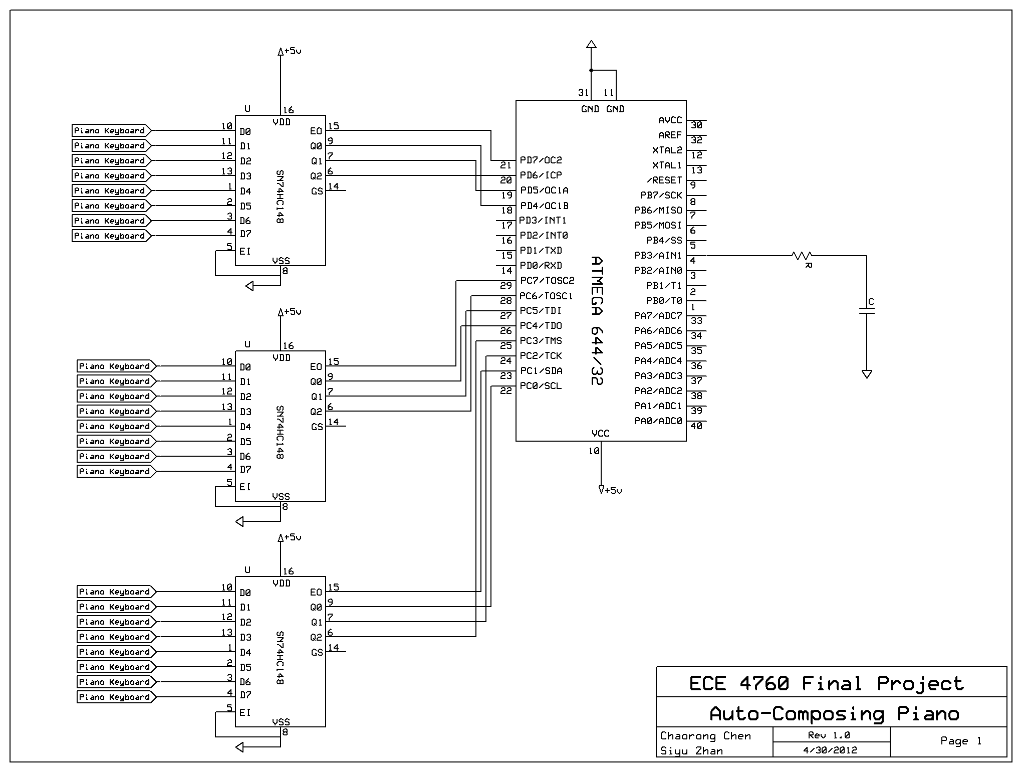
The 23 piano keyboard keys are each connected to a wire on the circuit board. To make them to active-low switches that are electrically detectable, we connected the wires to VCC through a 5 kilo-olm resistor. Thus, when the keys are idle, the output voltage is VCC and when keys are pressed, the output voltage approaches zero.
Due to the limited number of input ports on the STK 500, the 23 piano keys from the keyboard cannot be directly connected to the MCU. Instead, they are connected to three 8-3 hardware priority encoders to reduce the number of inputs. The piano keys are divided into three sections, each correspond to seven or eight inputs. Each section is directly connected to its own encoder and produces four encoded outputs: the Enable Output (EO) bit and A0 to A2 encoded bits. The total twelve outputs from the three sections are then connected to the input ports of the STK 500. The software will later decode and debounce the signals to determine which key has been pressed.
The idea of reading piano input via priority encoder is influenced by a previous year's project (A Keyboard Synthesizer Workstation by Matt Ferrari and Alec Hollingswirth).
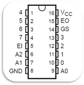
Figure 4: SN74HC148N Priority Encoder
Keypad Input
The keypad we used in this project is a 9-pin one with connectors on the top. The first four pins of the connector are connected to the four columns of the keypad and the following four pins connected to the four rows of the keypad. To figure out which button the user has pushed, a lookup table is set up in the software to determine the correct button. The keypad inputs are also debounced in software using a state machine we¡¯ve used for push buttons.
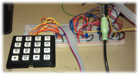
Figure 5: Keypad circuit
Low Pass Filter Output
The pulse width modulated signal output from the MCU carries high frequency components resulting from the edges of the square waves. Those high frequency noises sound very unpleasant in the speaker and would ruin the overall sound quality if not processed. Thus, we add a low-pass filter with a 10 kilo-olm resistor and a 0.1uF capacitor to get the time constant to be 1ms. This filter effectively eliminates the undesired harsh harmonics of the PWM output.
Software Design
I. Composing Algorithm
Sequencer Design
The sequencer we designed generates a piece of music of 15 bars long and the time signature of the music generated is a fixed 4/4. This time signature means that each bar is consisted of four quarter-note (crotchet) beats. The shortest beat that the algorithm calculates is eighth-note (quaver) beat, which means that for each bar, the sequencer needs to calculate eight different notes. For the total of 15 bars, the sequencer calculates 120 notes for a whole piece of each voice.
The goal of the sequencer section of our software is to generate two 1 by 120 matrices for melody and chord respectively which represents the notes to be played in sequence. A minus one entry of the matrix corresponds to an empty note, and all other non-minus-one entries correspond to a note in the range of C2 to C5, in which the entry value represents the distance between the note and C2. A semitone or half-step is counted as one in distance. The two matrices are then passed to FM synthesis process to generate corresponding notes using PWM output of the microcontroller. The notes generated by the algorithm should be relevant to the two notes that the user inputs and reflect the mood that the user chooses. Furthermore, it should obey most of the composing rules and sounds pleasant when played out on speakers. Following is a detailed description of our implementation of the sequencer that meets the above requirements.
Tone and Speed Determination
The first step in sequencer is tone and speed determination. The speed of the music is determined by the length of the quarter-note, which is determined by the time interval between two notes. Since we use TIMER1 interrupt to count time and play the next note when time1 counts to t1, we change the value of t1 to control the speed of music. After experimenting, we set t1 to 200ms for happy mood, and 350ms for tender mood. Therefore, in happy mood, the speed is 150 beats per minute, and in tender mood, the speed is roughly around 85 beats per minute.
For tone determination, a 12-note scale matrix (1 by 12) is created corresponding to different moods and notes input. Normal scale consists of 8 notes, but in this case, to include more possible notes for melody generation, we created a scale of 12 notes, in which the first 8 notes are exactly same as in normal scales, and the following 4 notes are the first 2 to 5 notes in a higher octave. The entry of the matrix represents the distance from current note to C2. For example, a 12-note major scale of C3 would be represented as:
[12 14 16 17 19 21 23 24]
To express different moods, we create major 12-note scale matrix for happy mood, and harmonic minor 12-note scale for tender mood.
The choice of the starting note for different 2-note input combinations can be tricky, because this choice, together with the tonality (major/harmonic minor), determines the 12-note scale from which melody is generated. The scale not only needs to include the 2 input notes, but also should span a reasonable range among the notes that could be played (C2 to C5). A scale too low or too high makes the melody sounds very unpleasant according to our experimentation.
Our final solution for tone determination is as follows. First we change both input notes into the range of C3 to C4 by changing it one octave up/down if needed. Next we calculate the distance difference between them, which should always be positive. Then we use the following lookup table to determine the starting note of the 12-note scale and generate the scale matrix based on the mood input.
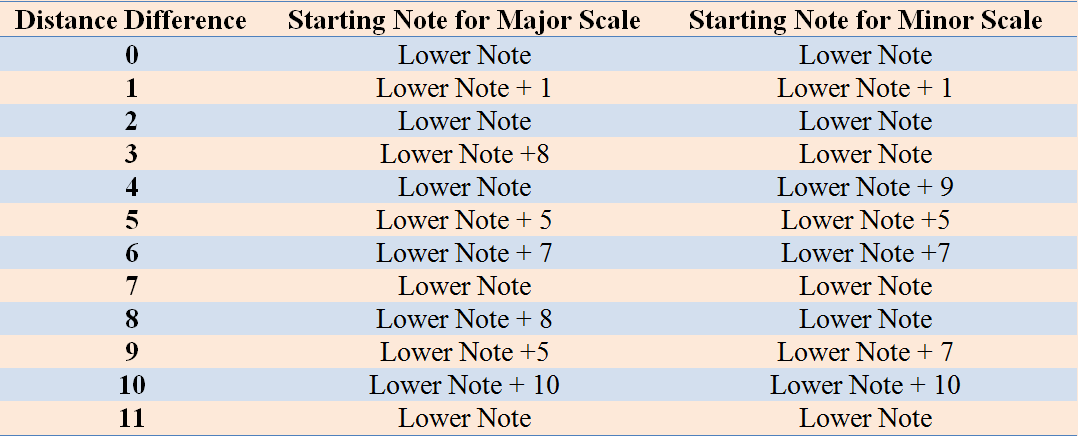
Figure 6: Tone Determination Lookup Table
Melody Determination
The melody determination process generates a 1 by 120 melody matrix. The entries of this matrix represent melody notes by their distance to C2, and -1 represents an empty note. There are two steps in melody generation, setting rhythm and setting tune.
Set Rhythm
As mentioned before, the whole piece of music generated consists of 15 bars, and each bar contains 8 eighth-notes with each corresponding to an entry in the melody matrix. To set the rhythm of the whole music, we chose 8 typical rhythm patterns for each mood (16 in total) from some classic pieces, and each rhythm pattern is exactly one bar long, which is 4 quarter-notes. Also the shortest beat in these rhythm patterns have to be eighth-note beat to be consistent with our system. A one in the rhythm pattern means that it is a beat and a zero means it is empty. For each bar of the 15 bars in the melody, a random number is generated to choose one of the eight rhythm patterns of the mood chosen. Also, to make the whole melody sounds more integrated like the real music, the rhythm of the 5th, 10th, and 15th bar is set to serve as an end to a musical phrase. In this way, the rhythm of the whole melody is determined.
One thing to note is that because it is very hard to change the delay time of a certain note without changing the timber of the sound using FM synthesis, for beats that are longer than eighth-note beat, such as quarter-note beat and half-note beat, they are represented as one eighth-note beat at first followed by a number of empty beats. We don¡¯t repeat the note several times for a longer note because that sounds very obviously as repetition rather than a note lasting longer.
Set Tune
The tune of the melody is set based on both the 12-note scale matrix generated in tone determination process and the Markov probability matrix. There are two Markov probability matrices, each corresponding to a mood. Both probability matrices are 12 by 12, and both the row and column indices corresponds to the 12 notes in scale matrix. The row index represents current note, and each entry in the row represents the probability of the next note being the note corresponding to column index. Since we use int8_t for most of the operations, the probabilities of each row is normalized to be sum up to 127.
The general process of choosing the next note for the melody is as follows. A random number between 0 and 127 is first generated. Then the system finds the row in probability matrix corresponding to current note and compares the random number and the cumulative probabilities of each column in the row until it exceeds the random number. Then the note corresponding to that column is chosen to be the next note. An example of this process is as follows.
if current note is C3 and the row corresponding to C3 in the probability matrix is:
[0 0 0 50 50 0 27 0 0 0 0 0]
and if the generated random number is 56, then the next note should be G3.
There are certain circumstances where the note generation does not follow the above process. The first case is the first two notes of the melody. The system is programmed to set the first two notes of the melody to the two input notes to make the music sounds more like a piece inspired by the two notes that the user played. The second case is that for notes longer than half-note, the probability of playing the first, fifth, and eighth note of the scale matrix is much higher than playing other notes, because these notes gives an ending feeling to a musical phrase.
Based on the above rules, the notes of the 1 by 120 melody matrix is filled when the corresponding beat in rhythm matrix is non-zero. For zero beats in rhythm matrix, the corresponding note in the melody is set to -1 to indicate an empty note.
Chord Determination
To ensure that the chord and melody creates a harmony in any case, there are three choices for a chord note to a melody note. It could either be 5, 7, or 12 semitones below the melody note. Five semitones below create a perfect fourth; seven semitones below create a perfect fifth; twelve semitones below creates the same note an octave down. These three choices are in perfect harmony with the original note and thus would sound pleasant in any case.
The system generates chord for the melody in the following way. Firstly, it only generates chords if the corresponding melody note is not empty. This is to ensure that the melody rhythm is clear and won't be disturbed by the chord. Next, there are 87.5% that there is a chord for a certain non-empty melody note. This is to make sure that there are some variations in the chord. Thirdly, a random number is generated to choose a chord for the melody note from the above three choices. In this way, the chord generated is always in harmony with the melody, and is not monotonous. The chord is also a 1 by 120 matrix where each entry is an eighth-note in a bar and represents the note by its distance to C2. A -1 in the chord matrix also means an empty note.
Train
If a user chooses to train the system himself, a Markov probability matrix is calculated based on the user¡¯s input on the keyboard. For the 24 keys on the keyboard, all keys lower than C3 is counted as one octave above because of the size of the probability matrix. All black keys are counted as the white key one semitone below it to ensure that all users¡¯ inputs can be recorded by the probability matrix.
The first step of training algorithm is to collect the times of every note played right after every note and construct a training matrix. The training matrix is also 12 by 12 and both the row and column indices represent the 12-note major scale starting from C3. Following is an example of building a training matrix. If C3 is played right after G3, then the entry of the fifth row (G3) and first column (C3) should increment by 1. The second step is when the user finishes all his input and presses Button 0 on the keypad, each row of the training matrix should be normalized to 127. If there is an empty row, 127 is assigned to the following note in the scale except G4. If the row of G4 is empty, 127 is assigned to C4. In this way, a raw probability matrix is built according to user input.
However, there is a large chance that the user might input some sequence that is not likely to generate very pleasant music. Therefore, after multiple times of experimenting, we decided to put the training matrix through a filter before it goes into the normalizing stage. For most of the time, an unpleasant sequence results from a large jump between notes, so we build a simple band pass filter that eliminates the large jump between notes. Following is a table showing how the band pass filter works:
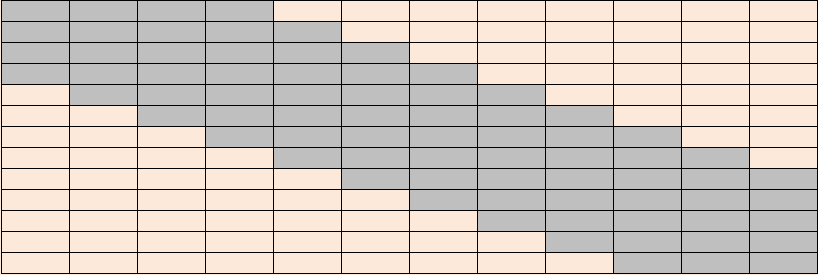
Figure 7: Band Pass Filter for Training
For each row in the training matrix, we keep the value of the shaded area and set all other entries to 0. In this way, our training algorithm works very well and is able to generate pleasant music relevant to the user¡¯s input.
In this way, our training algorithm works very well and is able to generate pleasant music relevant to the user¡¯s input.
II. Piano Synthesis
To synthesize the sound of a piano, we tried different synthesis methods including Karplus Strong algorithm and Frequency Modulation synthesis. We end up using FM synthesis since a combination of Direct Digital Synthesis (DDS) to generate sine waves and FM synthesis to modulate the signal produces a voice most similar to piano. As mentioned above, three piano sounds are generated at the same time in 16 kHz sampling frequency by the MCU.
Direct Digital Synthesis
Direct digital synthesis is a method of generating a pure sine wave by generating a time-varying signal. In this project, we use the 16-bit register as a phase accumulator. The higher 8 bits are used as the phase register for index array and the lower 8 bits are used as sine table lookup. The sine table is initialized in initialize function and updated in timer1 ISR to produce the base frequency.
The output frequency can be tuned by selecting the increment value in DDS. Since the output frequency is the inverse of the time it takes to overflow the 16-bit register, we get
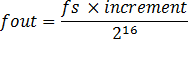
and thus increment = 4.096 * fout for 16kHz sampling rate.
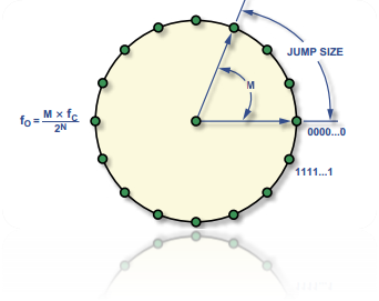
Figure 8: phase-increment in DDS
Piano Synthesis Using Frequency Modulation
FM synthesis is a form of audio synthesis where the timbre of a simple waveform is changed by frequency modulating it with a modulating frequency that is also in the audio range, resulting in a more complex waveform and a different-sounding tone. [4] The formula of FM synthesis used in this project is

In the formula, amp(t) is the modulating envelope and is a waveform of exponential rise and exponential decay which means
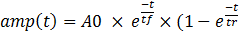
and it is the numerical solution of an ordinary differential equation calculated in Timer1 ISR using 8:8 fixed point calculation. f0 in the formula is the base frequency and is represented as inc_main in the code. The parameter A0, tf, tr, amp_fm, fm_depth and f_fm are all calculated in Timer1 ISR and can be controlled using parameters decay_main, rise_main, inc_fm, depth_fm1 and decay_fm1.
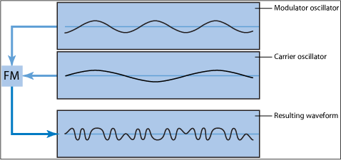
Figure 9: FM Synthesis Waveform
Timer0 PWM output
In this project, three FM modulated voices are generated in Timer 1 ISR to serve as main melody and chords, each with its own note sequence selected by the sequencer. The three voices are added together to OCR0A and output to the speaker through Pin B3 which is the PWM output pin for Timer 0.
Since we have three different voices, we used three different plucks in main to start playing a note by setting pluck to 1. And the time interval is controlled using time1 variable.
Alternative Piano Synthesis Method
Another popular sound synthesis method is the Karplus Strong algorithm. The Karplus Strong algorithm is particularly well suited for implementation on a microcontroller due to its simple arithmetic. It is also a very good method to synthesize plucked string sound including the piano. For these two reasons, we attempted to implement the piano synthesis using Karplus Strong algorithm for more than a week to get it working. However, we eventually gave up the method since the high frequency notes generated by Karplus are not similar to a piano and the system produces unwanted noise when Karplus was implemented.
Results
Speed of Execution
The sound produced at 16 kHz sampling rate is clean and similar to the one generated by a piano. It takes is 662 cycles plus 64 cycles which equals 726 cycles total for the Timer 1 ISR to synthesize the sound. So with OCR1A = 999, it takes 72.6 percent of CPU time to do piano synthesis. During the operation of the system, there is no observable delay in sound generation.
Accuracy
To measure the accuracy of the base frequencies, we used a deterministic, ascending sequencer with a long time interval to output sound wave in PWM signal and used an oscilloscope to measure the wave frequencies. The accuracy is within four percent of the actual frequency. For the hardware input, the D4 key on the piano keyboard is sometimes not detectable by the MCU due to the wiring of the keyboard circuit. We tried to re-solder the wire on the circuit board but it still wasn't working very well. So we used D4 sharp key for D4 key when user needs that input.
The Composing Algorithm
The result of the composing algorithm is very successful. It meets all the expectations and is able to generate a piece of pleasant music according to user's input. Tone, melody and chord determination works as expected in creating the melody and chord matrix. Training algorithm also works as expected to alter the probability matrix based on user's input. As for the quality of the music generated by the algorithm, currently there is no universal standard to test the quality of a piece of music, so it is hard to measure the quality of music accurately. The music generated by our system is very rarely to be unpleasant, and for around 40% of the time, it generates music that actually makes us feel very enjoyable. Therefore, we would say that the composing algorithm in all is very successful.
Conclusion
Overall, the auto-composing piano project was functioning as we expected. The music produced is similar to a piano sound and the composing algorithm is working well. For future improvement, we could use more machine learning skills to let the composer better learn the pattern of the music user inputs and composes music that are more sounding and catering to the user's preference. We could also use a solder board instead of STK 500 to increase portability and further reduce the budget of the project.
Applicable Standards
There are no relevant standards applicable to this project.
Intellectual Property
The idea of reading piano input via priority encoder is influenced by a previous year's project (A Keyboard Synthesizer Workstation by Matt Ferrari and Alec Hollingswirth). The code to perform the DDS and FM synthesis is a reuse of the code from Bruce Land's DSP page. The link to the page can be found here: Bruce Land's DSP Page
Ethical Considerations
With reference to the IEEE code of ethics, we completed this project in an ethical manner, and made sure that the finished project does not violate any ethical considerations. We accepted the responsibility that our auto-composing piano would not harm other people and not violating regulations and laws. We reported our results accurately and based on facts. We have not concealed the shortcomings of our device nor have we made untruthful claims about our project. We have sought and accepted criticism in the design of this project, and referenced the projects and research papers that are similar to our project. We have explained why we believe we are not infringing on any of their intellectual property in the design of our auto-composing piano. In the collegial spirit, we have tried our best to help our peers whenever they had any questions related and unrelated to our project without any discrimination. When designing the auto-composing system, we have also kept in mind the purpose of improving the understanding of technology, its appropriate application. We hope that this system would help people better understand technology's impact on music and how technology and art are well connected.
Legal Considerations
We do not violate anyone's intellectual property rights nor does our auto-composing piano cause harm to others. Since we do not broadcast any RF signals, we need not to be concerned with FCC regulations. Therefore, our project is in compliance with current legal standards.
References
[1] "Harmonising Chorales by Probabilistic Inference." Moray Allan and Christopher K.I. Williams. NIPS 2005.
[2] "A Hybrid System for Automatic Generation of Style-Specific Accompaniment." 4th Intl Joint Workshop on Computational Creativity, June 2007.
[3] SN74HC148 Priority Encoder Data Sheet, Texas Instruments. www.ti.com/lit/ds/symlink/sn74hc148.pdf
[4] "FM Synthesis." Wikipedia, The Free Encyclopedia. Wikimedia Foundation, Inc.22 July 2004. Web. 14 March. 2012
Appendices
Schematics
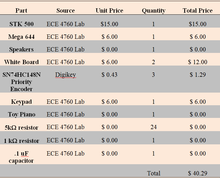
Part List and Cost Detail
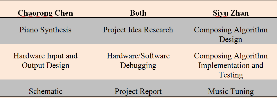
Work Division
Source Code
The code for this project can be downloaded here.
Acknowledgement
We would like to thank Bruce Land and Pavel Vasilev for their help during the whole semester. They have provided great advice and support for this project. We would also like to thank Matt Ferrari and Alec Hollingswirth for the toy piano they donated to ECE 4760 lab and their method of piano keyboard reading.