"A system to control and record RC car movements via a microcontroller."
Project Soundbyte
The Micro Kart 644 is a mobile device that provides additional capability to the traditional RC car experience. Allowable functions are recording multiple tracks, which consist of all user controls sent to the car over a 25 second interval, and replaying the tracks so the cars replicate the movements made during the recording. In addition, we interfaced with not one but two cars, which allows the user to mix the recording and playing of each car and come up with interesting double track replays. Applications of our system include recording a race between two cars and immediately replaying the race before your eyes.
Radio controlled cars are a classic toy for children, yet most improvements since its invention over 50 years ago have been mechanical in nature - improving their speed, power, or appearance. These improvements have greatly expanded the available market, as there exist a wide variety of toy-grade or hobby-grade cars, electric, nitro or gas powered cars, and a variety of accessories. We decided that by integrating a microcontroller into the controller of these cars, we would provide the user with even more capability to interface with their car, and overall improve their driving experience. Our first attempt was to create an arena where you could play a beacon-capture game in a battle arena against either an artificial intelligent opponent or your friend. When this proved too time consuming to get the video to work, we spent our remaining time implementing some features that did not require video, such as recording a car’s movements and playing them back.
High Level Design top
Overview
For our final project our goal was to create a system to easily control several RC cars through a microcontroller as well as add additional features to the functions of these cars through the use of the microcontroller. In order to accomplish this goal we looked for the simplest way to interface with the RC cars that still allowed us the most control. In addition, the lack of resources on the microcontroller constrained our design to be efficient in terms of memory usage as well as being reasonably low powered to allow the use of a battery as our power supply.
These criteria led our design to be structured into two portions: the interface with the controller, and the interface between software and user. The interface with the RC car controllers is a rather simple one consisting of a direct connection to the power and ground of the controllers as well as to the individual direction buttons. The user interface consists of four buttons and a 2x16 LCD display. The buttons control various settings of the program while the LCD screen displays the present status of the program.
The only standard relevant to our project is the IEEE radio frequency standards. The RC cars are driven at 27MHz and 49MHz, which puts it in the HF (high frequency) band, which is perfectly legal.
Trade-offs
While developing this design several tradeoffs were made between hardware complexity, simplicity of use, and feature-fullness of the final product. The simplicity of the hardware interface with the RC cars was a compromise we made to allow our an easy setup with the controllers, just six solder connections, while still allowing us as much functionality as we thought necessary, i.e. setting the output of the buttons or reading a user’s input at those buttons. Several more complicated schemes were discussed, including ones that would use additional external switches to allow the controllers to be unpowered on command, causing them to not control the cars when users would not be using them, which could be used to save power. Interfaces such as these slightly increase the abilities of our system, but at the cost of drastic increase in complexity that is unwarranted for such small gains.
For the software, the number of features implemented was restricted due to the size and speed of the microcontroller. The program was limited in its memory to only 4kB and as such a large store of tracks for the cars was infeasible. In addition, the rate of sampling had to be taken into account to ensure that replay was smooth, and accurate. Thus the software samples the cars input at a rate of 100 times per second and only store 2 tracks for each car, each lasting approximately 15 seconds. This uses up nearly all of the onboard memory and yet allows for an accurate replay for a reasonable amount of time.
Software Design & Implementation top
Microcontroller
The software for our final project runs exclusively on the microcontroller using the TinyRealTime kernel as the base. It consists of three multi-tasked functions, input, mode, and LCD_update, described below. These functions are all run independently by the kernel with no additional support from the microcontroller. The program starts with a few lines of initialization code after which control is given to the kernel to begin running the main functions of our program.
Input
This function is in charge of reading the state of the buttons, debouncing them and processing them correctly when they are pushed. It used a simple four-state debounce state machine for each of the four buttons, waiting for 20ms between each transition. After debouncing the buttons it checks if any of them have been reset, released, and are currently pushed in which case it performs the corresponding action. The actions are carried out by setting global variables changing the state of the program and signalling the other functions to use the updated values. This function is scheduled to run every 20ms.
LCD_update
This function performs the updates to the LCD based on the global state variables, allowing the user to understand what state the program is in. A compact representation of the state was chosen to fit all the information within the 2x16 character LCD display without the need for changing screens. There is a single large if else block to print the correct characters and values to a buffer for LCD. This is followed by a set of functions that causes only characters that actually changed between the current buffer and the previous buffer to display, which eliminates flashing and significantly speeds up the execution of this function. This function is scheduled every 200ms.
Mode
This is the function that implements most of the functionality associated with the RC cars. It controls the recording and playback of the inputs. During recording mode this function stores the values of the selected car’s controller inputs into an array. This is actually an inverted array because the controllers are active low but the inversion is handled during playback since we have to do some more bit-masking to get the correct data out of the array anyways. As stated when in playback mode the program simply starts at the beginning of the array and places each byte after some bit manipulations onto the pins connected to the controllers. At the end of the array we loop to the beginning allowing interesting repeating patterns to be created. This function is scheduled to run every 10ms to attain maximal accuracy while still keeping the amount of memory needed for the array within the bounds set by the onboard memory of the microcontroller.
Hardware Design & Implementation top
Hardware Overview
The hardware needed by the Micro Kart 644 was mostly already finished (see Early Work) - we needed to solder wires to the controllers’ buttons to allow the microcontroller to control them. In addition, we required an LCD display to be connected to Port C of the microcontroller. This was done by soldering female headers to a second solderboard as well as a ribbon wire to connect to the lower solderboard which contained the microcontroller. We replaced the power supply with a 9V battery, making our project very mobile. Finally, we used pin/header connections whenever we could. so that controllers could be added/removed easily without desoldering connections.
Hardware Diagram
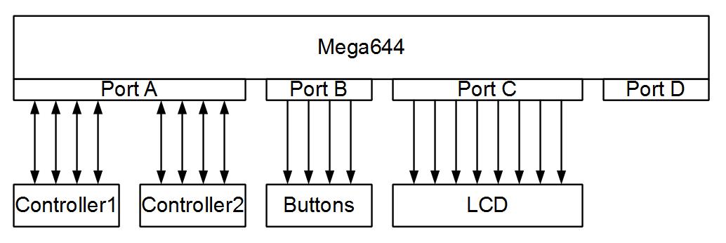
Overview of Hardware Design
Results top
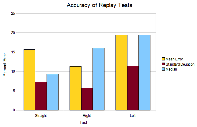
We performed three tests for the accuracy of our system - the car traveled in a straight line, a turn to the right, and a turn to the left. We then replayed the tracks and measured the distance between the final location of the car on replay versus the actual final location. The percent error is the difference between final locations divided by the total length the car traveled.
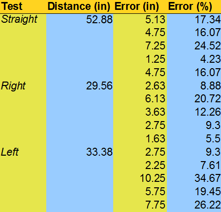
Table of Accuracy Test Results
Graph of Accuracy Test Results
All tests show mediocre performance, with the average error ranging between 10 and 20 percent and a fairly large standard deviation. We believe that the error seen is due to three sources - initial placement of the car, sampling, and dead reckoning/accumulation of error. All three significantly contribute to any differences between initial runs and their replay. However, as is clear from the pictures, the error was due to a loss in accuracy, not in precision, because the individual replay were very similar to each other. Ways to improve our accuracy would include decreasing the length of the track as it would decrease the potential for accumulated error, increasing the sample rate, and ensuring the car is placed in the exact same position for each trial run.
Early Work - The Battle Arena top
Design and Concept
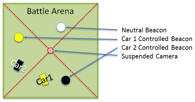
Our original design was much more complex than our final project. It consisted of a battle arena for the cars to play a beacon capture game, where a car captures beacons by driving over them. Each car obtains points proportional to the time they have captured a beacon, and the first car to 1000 points wins the game.
We wanted to implement an artificial intelligence component to the game, where a user could select an opponent strategy to play against. This required mounting a video camera on the top of the arena and perform real-time image processing to locate the cars and give the AI information to make playing decisions. This task is separated into two parts - generating an AI which, given a representation of the state of the game from our image processing, returns a destination the car should go to, and implementing a control algorithm to actually drive the car to the destination.
Battle Arena Concept Sketch
To evolve a strategy, we could not use the actual arena, as the algorithm requires thousands of trials competing between strategies, and the length of each real game was such that it was unfeasible to run the algorithm using real trials. Instead, we coded a simulator in Java which simulated a game between two cars playing their own strategy. Then, we coded our own genetic algorithm to evolve strategies using results from the simulated games.
To get our video working at a reasonable frame rate, we needed three different external pieces of hardware - the camera, an analog-to-digital converter (ADC), and an external SRAM - to correctly interface with each other and the microcontroller. This was very difficult because we wanted at least 10 fps, which required reading analog data at 500kHz and digital data at 20MHz. No prewritten interfaces would work at this frequency, so we had to write all code from scratch in assembly to get cycle-accurate signals.
To interface with the cars, we needed to open up the controllers and solder wires directly to the control buttons so we could control the cars directly from the microcontroller.
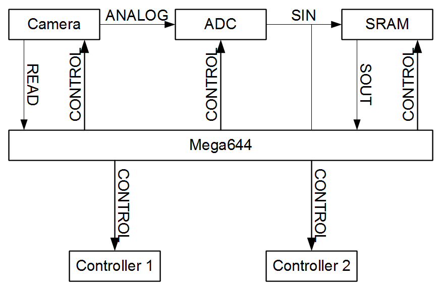
Battle Arena Top Level Design
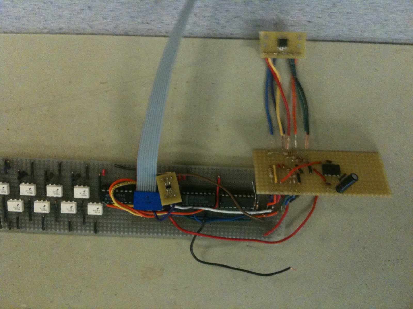
Battle Arena Final Soldered Circuit
Hardware - The Battle Arena
The hardware for the battle arena ended up being much more difficult than expected to work with. Due to our requirement of a high frame rate, we could not use the microcontroller’s built in ADC, and opted for an external one which operated at 20MHz. In addition, the size of the SRAM on-chip was insufficient to store a single image from our camera, and thus we needed to interface with a larger, external SRAM.
We picked the Gameboy Camera © as our mounted video camera, which serially outputs analog grayscale pixel data at a frame rate of about 30 fps. We chose this camera because of it was inexpensive and provided the exact functionality we needed, namely low resolution and high fps, because we were limited by the computational power of the microcontroller. We used Daniel Herrington’s article “Easy Image Processing: Camera Interfacing for Robotics” as a guide on how to interface the camera with a microcontroller.
The SRAM was 256Kb low power serial SRAM (N25S830HA). We chose this SRAM specifically to have serial inputs and outputs, as a normal SRAM would require setting 16 bits for an address and reading a byte of data, which would severely limit the number of ports we could use for other applications. We chose 256kB because our image was a 128x128 greyscale pixel array, and each pixel was a byte. One challenge with the SRAM was its supply voltage was 3.3 volts, while our microprocessor used 5V. We needed to level shift all signals to the SRAM, and the noise margin to any output of the SRAM was very small for a “1.” Finally, this SRAM could be run at 20MHz, which was great because we could use a 20MHz crystal oscillator on our microprocessor and simply fuse the MPU’s clock to an output pin to use to clock the SRAM.
The ADC (AD7478) could make a conversion at 1 MSPS and took 5V supply voltage. It has a 16 bit output, with the first 4 bits and last 4 bits being all zero, and the middle 8 are data. This required more software to enable the SRAM only when the data from the ADC was valid.
The RC cars’ remotes have four buttons - forward, backward, left and right - which grounds a signal to the internal controller if pushed. To replicate this, we soldered leads to these signals and attached them to pins on the microcontroller. When we allow the user to control the car, the pins are set to high impedance to protect them. When the microcontroller controls the remote, it can set its pins to ground to “push” a button.
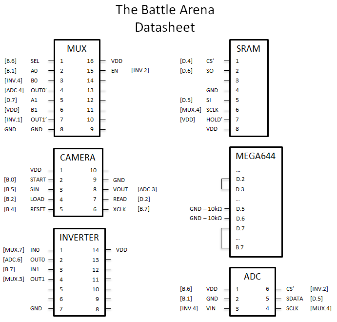
Battle Arena Datasheet
Software - The Battle Arena
The software for our initial project consisted of several parts: the genetic algorithm and simulator, run on a computer, the control of the camera, external ADC, and SRAM, run on the microcontroller, and the image processing and RC car feedback control system, also run on the microcontroller.
Evolving an Artificial Intelligence
In order to generate a game strategy (artificial intelligence) for the RC cars using a genetic algorithm, many iterations must be run simulating the game being played by different control algorithms. The genetic algorithm will then use this data to pick strategies that do well and merge them together with slight random changes and evaluate the next generation. As more simulations are performed, more strategies are evaluated and the population becomes better and better at playing the game. The amount of computation necessary for this process requires that an actual computer be used for this step and that only the final and best strategies be run on the microcontroller via a lookup table.
The methodology behind genetic algorithms is copulating ‘fit’ bit strings to create more fit children, and by repeating this process result in a population of very ‘fit’ bit strings and thus good strategies. The process of selecting ‘fit’ parents is directly correlated with their performance in a fitness function, which in this case is the speed in which they win the game. The bit string’s copulation involves two random processes - crossover and mutation. To perform crossover we first determine with some probability whether crossover will occur at all. If crossover is to occur then we randomly select a location in the genome and copy one parent’s genome before this point to the child and the other parent’s genome after this point to the rest of the child’s genome. Mutation is simpler in that the algorithm will with some probability for each gene change the output randomly. Our genetic algorithm also used an elite selection method of two individuals followed by fitness proportional selection for the remaining parents. This means that the two best individuals of every generation will always be selected as parents, so we never ‘lose’ progress.
The genetic algorithm and associated simulator were both developed in Java. The genome for the algorithm consists of a position the car should move to, encoded in binary, for each possible game state, where the game state consists of the state of each beacon, the car’s current, and the quadrant the opposing car is in. The encoding of the output position, was stored in a single byte, but due to the size of the maps being small was split into the x position in the first 4 bits and the y position in the last 4 bits. Given this representation the mutation operator was changed from a fixed probability operator to one that assigned less probability to the higher order bits of each index, so that it would be unlikely, but not impossible, for the car to change its behavior from one side of the map to other in a single mutation.
The other very important difference between this algorithm and a more standard genetic algorithm is that the fitness function is not static given the same genome. This occurs because the fitness of each individual is determined as its average performance against the rest of the population. Thus even the elite individuals can lose their place if the rest of the population becomes good enough to beat them. This type of fitness function should force our population to avoid local maximums more easily as they are actively competing so any change in one individual can move all other individuals in their fitness values.
In order for the genetic algorithm to run quickly the program was threaded such that at any time during the competition phase, several simulators are running, which on a modern multi-core machine provides a dramatic performance boost. In addition, for usability a graphical display of the simulators output was created to illustrate how the individual algorithms actually perform.
Other Software
The remaining software must be run on the microcontroller and consists of functions to setup the camera, ADC and SRAM to interface with each other without further intervention by the microcontroller, a function to analyze the image from the camera and determine where the cars are, and finally a function to move the cars according to the genetic algorithm based on feedback from the image processing.
Drivers
The camera, external ADC and SRAM all use serial interfaces. In addition since we need to operate at high speeds to capture and process images before the cars moved too far off course, the microcontroller needs to do as little work as possible to allow for the most time to process the image.
The first part of the microcontroller code was a one-time initialization function to reset the camera and set its control registers to values that would produce a good image at an acceptable frame rate. The camera had 8 registers each of which needed to be set before capturing an image, but once capture started it will continue automatically.
Ideally, the limiting factor for the update speed of our software would be the maximum framerate of the camera. In order to achieve this maximal framerate we were required to read a pixel data value every 2 microseconds, or at a rate of 500 kHz. Having the ADC process a pixel every 2 microseconds is not an issue but if the microcontroller were needed to spend even only four cycles for each of these transactions already 10% of the CPU time would be used up. To solve this issue we setup a hardware timer at the rate of 500kHz which turned on at the start of reading an image from the camera and toggled the chip select pin of the ADC which was all that was needed to have it produce an 8-bit digital value. The next step in capturing the image was to move the result of the ADC to the SRAM.
Because of the way the ADC works when it is operating at 500kHz it will actually be outputting the individual bits at a rate of 20Mhz so we need to have the SRAM set up beforehand to receive all of these bits at max rate, and once again we must put the SRAM in a steady state such that the microcontroller does not need to intervene for every bit or even byte we right. This was accomplished by putting the SRAM into a burst write mode, again through assembly for cycle accurate signalling, in which it will write all data received on the serial input is written to increasing addresses in the SRAM. Unfortunately due to the nature of the ADC it will output zeros before and after the actual value and so the SRAM will hold extra zero bits that will need to be accounted for when accessing the pixel values.
Image Processing
The last piece of software written was in charge of finding the cars in the image. Our two cars are yellow and black, so picking them out of a greyscale image would be very easy due to their difference in color. To simply the image processing even more, we decided the make the background of the arena green, as it was between black and yellow. The image processing simply compares the pixel value to a theshold to tell whether it is the black car or yellow car.
The image is much too large to read in entirely - however, since we know where the cars were in the previous frame, we only need to analyze the pixels in a certain radius around the previous location of the car.
Though all this code was written, it was never tested because it relied on using an image, which we never got working.
Car Controller
This was the final software that would have needed to be written for the battle arena to work. However, it depended heavily on receiving processed image data to run. Because we never got all the hardware working, we were unable to write any code addressing this part of the project.
Reasons for Failure
Initially, all hardware was constructed and tested on a whiteboard, but once we realized the inductive coupling of the long wires was a large source of noise in the system, we were forced to move prematurely to a solder-board. This made other changes to our board difficult because any change required desoldering and resoldering connections.
The issue that was the ultimate reason for our failure to complete this project, and the reason we switched projects, was our inability to integrate the SRAM with the camera and external ADC system already setup. After several weeks of work the camera worked correctly, it pushed its data through the ADC which converts it correctly, but the SRAM when written to in burst mode and then read from in byte mode was producing the same sequences of unintelligible bits. Regardless of any change in our code to delay or change the values being written to the SRAM.
There are several reasons why this issue became the project ending problem it was. First, we did not have a standalone test program for the SRAM as we did for the camera. Second its interface was significantly more complicated than the ADC, which was the only other component not to have its own individual test case. Third, it was operating at 20MHz which was also the clock frequency of the microcontroller itself. The combination of the last two factors caused the assembly code used to setup the SRAM to be exceedingly complicated - this would suggest that making a test case specifically for the SRAM would be helpful but by the time we realized this it was a little too late. Finally, at one point while debugging the SRAM we broke it and had to order a replacement which delayed progress on it by 4 days, a significant amount of time.
Other reasons for the projects lack of success include lack of firm deadlines for when certain parts of the project should be done. If we had set specific deadlines than we would have seen that we were not on pace to finish and could have switched projects earlier giving us more time to improve our secondary project.
Conclusions top
Final Thoughts
Overall the project was a success however disappointing it was to have to abandon our initial goals. The final project is still interesting and enjoyable to use. The goals for the new project, recording and playing back commands to the RC cars on different tracks, were all accomplished. Analyzing the performance shows that our playback performs reasonably well and most of the error seems attributable to minor fluctuations in the conditions of the floor, car, and initial position of the car. The user interface is sleek and natural to use, and the appearance of the system is also well done giving the overall project a nice level of polish.
Future Work
Having switched to the new project so late in the design cycle it was hard to implement as many extra features as we would have liked, but what follows is a brief discussion of possible extensions and estimations of their cost in labor. One interesting system we nearly implemented was the addition of an infrared finish line. In our rather simple design it consists of an IR emitter and collector, separated by several car widths, that were attached to a long ribbon cable to the microcontroller. This would allow the user to place the finish line anywhere on the course and then the microcontroller could alert the user via the LCD, or with some modification to the hardware stop the controllers so it would be possible to tell who won the race.
Another change that could a significant level of competition at the cost of much more hardware complexity and software complexity would be to take more after our namesake and add the ability to shoot virtual turtle shells. One potential way to do this would be to attach an IR LED to the front of each car and a sensor to the back. Then connect the sensor to a schmitt trigger that has its output connected to a switch like transistor that controls the power to the motor. This mean that when one car got close enough to the other it could shut it off, and take the advantage in a race or other competition. A minor adjustment that would make this encounter more interesting would be to have the switch be attached to a capacitor so that it would take a significant amount of time, a few seconds, to turn back on.
Intellectual Property Considerations
The majority of work for this project was completely original. However, we did heavily rely on Daniel Herrington’s article “Easy Image Processing: Camera Interfacing for Robotics” as inspiration for our own camera circuit. In addition, we used the TRT (tiny-real-time) kernel written by Dan Henriksson and Anton Cervin in our final design.
Ethical Considerations
During our project, no ethical considerations were brought up. We believe the project is consistent with the IEEE Code of Ethics, as we accept all responsibility for our project and did our best to acknowledge the help and work of others. In addition, the societal impact of the Micro Kart 644 is very low. Our project is not dangerous since the cars do not have significant force to hurt anyone, even if is completely out of control, and all voltages on the system are small. Overall, it is a simple toy that does not pose any danger to adults.
Appendices top
A. Parts List and Costs
We ordered all electronic parts from Digikey.com, and the RC cars and Gameboy Camera from Ebay.com.
| Category | Item | Vendor | Unit Cost | Quantity | Total Cost |
|---|---|---|---|---|---|
| Electronics | Prototype Board | ECE 4760 Lab | $4.00 | 1 | $4.00 |
| ATMega644 | ECE 4760 Lab | $6.00 | 1 | $6.00 | |
| 9V Battery | ECE 4760 Lab | $2.00 | 1 | $2.00 | |
| 1Msps 8-bit ADC AD7478 (Digikey P/N:AD7478ARTZREEL7CT-ND) | Analog Devices | $3.21 | 1 | $3.21 | |
| 20MHz Serial In Serial Out 256k(32x8) SRAM (Digikey P/N:766-1043-ND) | ON Semiconductor | $3.47 | 1 | $3.47 | |
| Mini RC Car | Create Toys | $10.00 | 2 | $20.00 | |
| LCD Display (2x16) | ECE 4760 Lab | $8.00 | 1 | $8.00 | |
| 4 Grouped Push Buttons | ECE 4760 Lab | $0.00 | 1 | $0.00 | |
| 10K Potentiometer | ECE 4760 Lab | $0.00 | 1 | $0.00 | |
| Connections | Solder Board (6 inch) | ECE 4760 Lab | $2.50 | 2 | $5.00 |
| Header Pins | ECE 4760 Lab | $0.05 | 150 | $7.50 | |
| Wire | ECE 4760 Lab | $0.00 | N.A. | $0.00 | |
| Physical Structures | Rubber Feet | ECE 4760 Lab | $0.00 | 1 | $0.00 |
| #4 2-inch Bolts | ECE 4760 Lab | $0.00 | 4 | $0.00 | |
| 1-inch #6 Spacers | ECE 4760 Lab | $0.00 | 8 | $0.00 | |
| #4 Nuts | ECE 4760 Lab | $0.00 | 4 | $0.00 | |
| Total | $55.18 |
B. Source Code
The microcontroller soucre code is available here.
C. Specific Task Breakdown
| Colin Schmidt | Both | Adam Izraelevitz |
|---|---|---|
| Microcontroller code | Debugging | Soldering, hardware implementation |
| Website formatting | Website content | Website graphics |
| Hardware design |
References top
This section provides links to external documents, code, and websites referenced and used throughout the project.
References
Acknowledgements top
Our understanding of genetic algorithms came from Professor David F. Delchamp’s class ECE 4271, “Evolutionary Processes, Evolutionary Algorithms, and Evolutionary Games.” Many thanks go to Bruce Land, Pavel Vaseliv, and Ninoshka Singh for their help in finishing our project.
