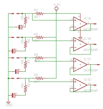
Thermistors have used as a low cost temperature sensor which is constructed of solid semiconductor material which exhibit a positive or negative temperature coefficient. We have used a 10k NTC Thermistors. Since Thermistors are basically thermal resistive devices, a signal conditioning circuit is necessary to convert the change in resistance into a change in voltage. All Thermistor sensors have been connected in series with a 4k7Ω. The output of the voltage divider is then filtered and isolated using a buffer which has a very high input impedance and low output impedance to isolate the voltage divider circuit from the microcontroller. MCP6004-I/P Quad Op Amp was chosen because it has four op-amps on one chip. This made it easier to build and made the circuit layout smaller. A look up table in the microcontroller was used to convert each temperature. Temperature sensors had to be calibrated before being used.
Figure (4) signal conditioning circuit
In this project, there were six actuators to be controlled; three fans, 2 pumps and Peltier Heater/cooler. All of these actuators have motors in them and require a high current to be driven. A low side gate driver IXDN604PI has been used to drive a power MOSFET. This gate driver has two outputs can sink 4A of current which producing voltage rise and fall times of less than 10ns. The input to these drivers is virtually immune and provides sort of protection to the microcontroller. To slow down the fast switching of the gate driver, a 10Ω resistor is connected at the gate of the driver. When signal is applied to the gate driver, it turns on the MOSFET which in turn pulls the load down to ground. The input channels of the gate driver have to be pulled down by a resistor to keep it from floating around. MOSFET (IRLB3034) has been used to drive the actuators; this MOSFET was chosen because it can sustain up to 195A through the drain and it’s RDS (on) =1.4mΩ; dissipating about 1Watt when ID is 28A (the Imax required by the Peltier). Two MOSFETs have been connected in parallel to provide the required current of the Peltier heater/cooler.
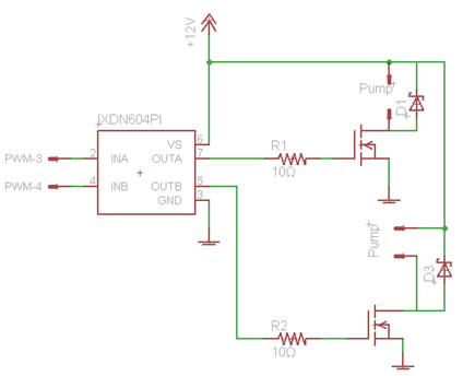
Figure (5) Actuator Driving Circuit
We have used the Arduino Fio board for satisfying the Microcontroller requirement as shown in figure (6). It houses a Mega328 controller. Various features offered by the board, especially the interface with the Xbee modules for wireless communication is a very advantageous feature for us. Also it has all essential peripherals like the ADC channels, PWM channels and UART lines drawn out from the board. Hence it acts as a tiny module with all the features essential to our project. Although this board provides a good hardware platform, it comes with a bootloader program which enables us to use a very simple programming language. This language is meant for beginners and is very user friendly, but is highly inefficient. We have been using C to program the board but on several occasions it created a compatibility issue and caused the system to perform randomly. This was a trade-off where we had to combine the use of the Arduino language and C in order to maintain compatibility and efficiency. Also, since it is a development board, we do not have access to all the port pins on the controller. Hence in cases where we need to use the pins which are not directly available on the board, it can fail to meet our requirements. Also the crystal on the board is configured as 8 MHz, which can is well below the maximum limit on clock frequency. So it means that we are not utilizing the full capabilities of the controller.
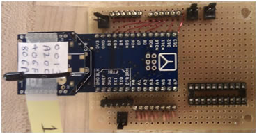
Figure (6) Controller board
Measuring the power consumed by the Peltier Heater/Cooler is a feature that we decided to add to the hardware design of the system. The maximum current the Peltier module requires at 12V is 28A, with this in mind, we decided to use ASC 712 current sensor which has a current sensing range of ±30A and it is based on the Hall Effect Current
Sensing. Figure (7 ) shows the schematic diagram of IC connection. This IC requires 5V supply. We had to add a linear voltage regulator to provide the necessary voltage. The output of sensor had to be stepped down to a range of 0-3.3V using a voltage divider circuit. To accurately measure the power consumed by the Peltier module, we had to take instantaneous measurements of current and voltage. Voltage measurements were taken exactly at the terminals of the Peltier module to take into account any voltage drop across the Peltier wires. Both voltage and current were sampled only when the Peltier is on and to be able to do that, we had to synchronize the ADC measurement in the microcontroller such that it starts sampling when the PWM signal is on as shown in figure (8)
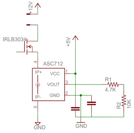
Figure (7) current sensor circuit
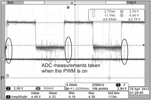
Figure (8): PWM & ADC synchronization