Figure (9) Ground bouncing
Stage 1
This project involved a lot of hardware testing and debugging since the circuit has 4 different voltage levels; these are 3.3V, 5V, 12V and 24V. These voltage levels existed to meet the voltage supply needs by different components in the circuit. To get 24V needed by the Peltier Heater, we had to connect 12 fat power supplies in series. These two power supplies introduced a considerable amount of noise to the system. Having different voltage levels on one circuit board was a big challenge in getting the circuit to work. After we finished the design of the layout of individual circuits, we started thinking about the complete layout of the circuit. The layout of the circuit was done such that different high power components were separated from the low voltage part of the circuit. All Actuators were connected to the circuit board from one side using Molex connectors. Depending on current required by each actuator, 2, 4 and 6 pin connectors were used. Soldering the circuit was done on different stages to make sure that each part of the circuit worked fine. Each actuator output was tested by connecting a resistive load to it. This was done to make sure that there was no short circuit existed and that the gate driver and the MOSFET function as expected. In addition, we did not want to blow out any of the actuators until the circuit is completely tested.
Temperature sensors signal conditioning circuit and the controller board were each soldered on a separate piece of board that was mounted on the main actuators board. This was done to meet the modularity requirement of the project and to facilitate the replacement of the controller.
Even though these circuits were meant as prototyping and only as a mean to get the HVAC rig functioning, we paid our best efforts to avoid any nasty connections. Temperature sensors circuit conditioning circuit was soldered using a Kester 331 flux solder which is free from any toxic metal and it is a water soluble flux core solder which is used with a flux bottle which worked well for soldering up the board without rosin residue. This flux gave a much cleaner result because it completely washes away under the tap. The only downside is that we had to dry the circuit board with compressed air before we can test it.
Stage2
The second stage of the hardware testing involved connecting actual loads to the circuit. These loads are 3 fans, 2 centrifugal pumps and 1 peltier Heater/cooler module. Most of these loads are inductive and switching inductive loads generate transient voltages and spikes of many times the steady state value. These transients can destroy the controller especially in our case, they share the same ground. scotchy diodes were connected across both pumps. These diodes were reverse biased such that they will allow current to pass through them when the pumps are turned off.
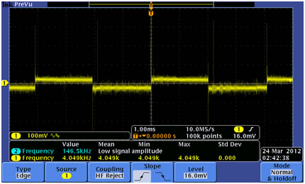
Since we had a noisy power supply, a highly voltage rated electrolytic capacitor was connected across the supply to filter out some of the noise. A think ground plane was made especially for the Peltier heater since it passes 28A through the ground plane and that causes ground bouncing. Figure (9) shows a ground bouncing at the controller terminal which was caused by the high power switching. This causes wrong readings, and can cause the controller to fail.
Having a fat low inductance ground plane helps tremendously. We connected 0.1uF decoupling capacitors for every IC between Vcc and ground to bypass the supply inductance. Also, since the Op Amp signals from the signal conditioning circuit travel a distance to be connected to the microcontroller ADC channels, a 10Ω resistor is connected at the Op Amp output so that the capacitance of the cable does not load the Op Amp and cause it to oscillate.
Figure (9) Ground bouncing