Figure (13a ): Two PI loops response Vs one PI loop................. Figure (13b ): Peltier PI controller response
The results obtained from this project were a completely functioning scaled HVAC system that can be controlled wirelessly using Zigbee protocol. A wirelessly tunable decentralized multiple input, multiple output PI controllers were successfully implemented and tested. The details of the results obtained are as follows:
To accurately measure the temperature of the HVAC setup, all Thermistor sensors were calibrated and compared to their datasheets. We calibrated the sensors by immersing each sensor in to a cup that has boiling water in it and as water cools down, we take measurements of the temperature of the water using an accurate thermocouple temperature sensor and we measure the corresponding resistance of the Thermistor at that temperature. Due to the fact that we had many temperature sensors in the system, we only used one look up table for all of them.
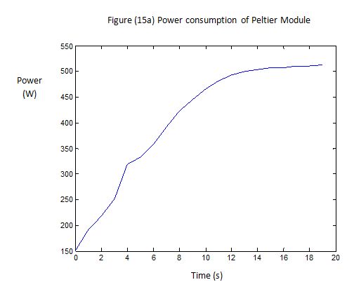
To accurate measure the power consumed by the Peltier Heater, we synchronized the measurements of the Peltier’s voltage and current such that we only sample the ADC when the PWM (OC2RA) goes high. In addition, we measured the voltage of the Peltier exactly at its input terminals to avoid any voltage drops across its wires. This gave us a fairly accurate instantaneous power measurement of this power hungry component.
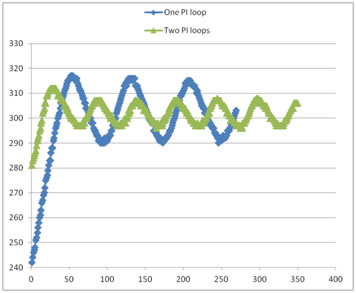
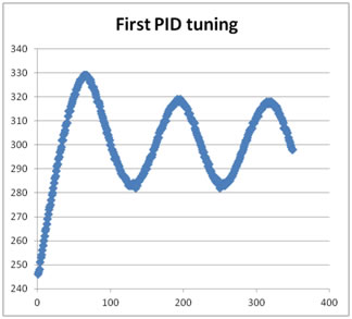
The response of the PI controllers were very satisfactory since we were able to obtain the set point with in ±0.7ᵒC. Figure ( 13b) shows the response of implementing one PI controller on the Peltier heater. We were able to get a better response when two PI loops were implemented as shown in Figure (13a). Using GUI interface greatly helped us tuning the PI controllers wirelessly.
Figure (13a ): Two PI loops response Vs one PI loop................. Figure (13b ): Peltier PI controller response
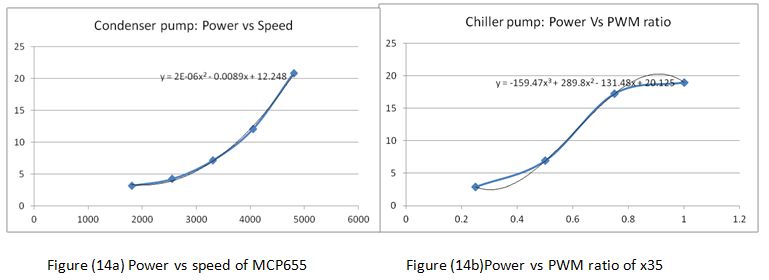
Measured data from both the condenser loop pump and the chiller loop pump were collected to be compared and contrasted with the pump models that have been designed using Modelica language. Further analysis will be carried on this project to calibrate HVAC models and build a Model Predictive Controller that will take into account systems dynamics to optimize best set point to be sent to the local PI controllers.
The results of this project were very satisfactory. We established a very responsive HVAC system that is wirelessly controllable. We established a very good understanding of multivariable feedback controllers design and tuning. There were some issues with hardware debugging and ground bouncing and this gave us very rich hands on experience especially when we are pulse modulating high power components and inductive loads. We were able to identify some hardware limitations which are listed in the future improvements of the system. The implementation of the wireless network gave us a concrete understanding of different protocols and the drawbacks of each one.
Important Design Considerations & possible design improvements
Grounding:
When dealing with switched mode operation on devices, it is necessary to have a sufficiently large ground plane to suppress the transients. Especially in high power circuits like the one we have, needs a large area to ground the current flowing in the circuit. If the ground plane is not sufficiently large, frequent switching causes the ground level to bounce and hence affect the performance of the microcontroller. There is also a possibility of unpredictable behavior of the controller or its peripherals.
Optical Isolation:
As discussed above, grounding can be an issue on the performance of the low power devices (controller, sensors etc) when using along with high power switching devices (pumps, heaters etc). Hence it would be a good idea to isolate the low power and high power devices to stabilize the performance of both. An opto-isolator (capable of accommodating the desired bandwidth of the switching signal) would serve this purpose by transferring the low power switching signal optically at the high power end. This would practically isolate the two power levels. IC’s are readily available for this purpose. Current design does not have this feature but it would be good to have it during future improvements.
Possible Improvements
Even though we did our best in building the hardware, it is still considered as a prototype and may not be very robust if a lot of students will use it. The current connectors between the controller and its inputs, output is not robust. All connector wires and jumpers should be replaced with a soldered wires or use ribbon cables to get a solid connection. The circuit needs to be contained in a transparent box to protect it from water leakage in the system and a fan is required to cool down the current IC sensor and the Peltier power connector. We are currently using one look up table to get the temperature readings for all thermistor sensors, instead one could have included a look up table for each sensor, however execution time and memory space needs to be considered. Finally, to protect the actuators from any sudden current transients, one could use fuses in line with each actuator to protect it from surge currents.