Board Cleaning Robot
Le Zhang & Michael Lathrop
Introduction
-A Roomba for boards
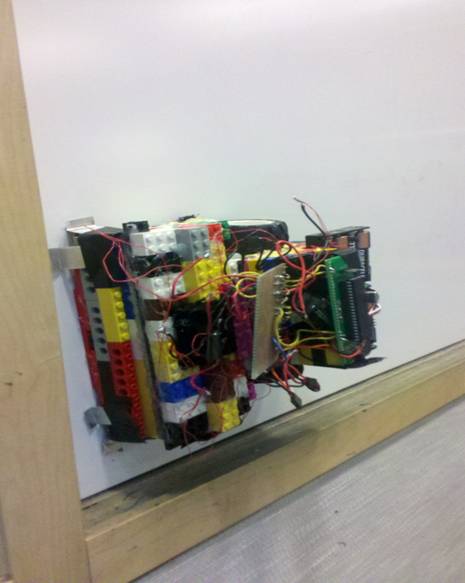
For our ECE 4760 final project we created a board climbing robot capable of cleaning the board autonomously. The robot uses neodymium magnets to stick to the board and moves across it with two continuous servo motors. It has bumper sensors on all four sides and keeps track of its orientation with two 1-axis accelerometers. The bot sweeps the board row by row starting from the top left corner. The bot can start at any point on the board and reposition itself to the starting point.
High Level Design
Rationale
We wanted a project that was not only impressive and innovative but also something practical. The board cleaning bot came as something in our desire to create a usable product. One of our members first considered the idea of an automated board cleaner while in a classroom years ago. What he first noticed was that during long lectures, professors had to pause to erase the boards every time the boards were full. It would be much more efficient time wise to have a bot do the erasing on a board while the professor lectures on another. Other applications are for college classrooms with exceptionally tall boards that are hard to reach. As far as we have researched, we could not find any reference about a board cleaning bot online. Our TA has even suggested that we patent this idea if it hasn’t already been.
Logical Structure
The design process for the bot was primarily focused on the hardware and chassis for the bot. For our proof-of-concept, we wanted something simple and flexible to work with. Since we had no idea of how we could get our bot sticking to the board and moving, we had no choice but to use legos to construct the chassis. Not only was the legos free, it also allowed us to easily make changes to the chassis.
The first stage of our work was to put together a chassis that can stick without sliding. We modeled our bot with Parallax’s boebot since it is the simplest to deal with. We attached two wheels to move and rotate the bot and made the chassis contain space to hold a standard board eraser. We also made sure to have the chassis as low as possible so that its center of gravity is as close to the surface of the board as possible.
Once the chassis stuck firmly we tested its movement on the board to make sure that it can climb in all four orientations without issue. At the same time we worked on implementing the accelerometer and bumpers to make sure that we can get a proper reading. Finally, with the chassis done, we attached our sensors into the chassis and proceeded to testing our code. To debug our code with the bot running on the board, we tethered the protoboard’s uart to an STK500 and read its values through putty.
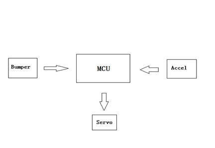
The following is a diagram of the sensors in relation to the actuators:
Hardware/software Tradeoffs
We needed the accelerometer and bumpers to react within 100ms, because the bot can only move so fast on the board. All of our sensor readings came from interrupts and the actuation came from PWM signals from TimerB, additionally our code did not require any demanding calculations, so we had no performance issues that required any tradeoffs.
Standards:
The accelerometers we used were analog so we did not have to use the I2C standard. The bumpers in effect are simple switches that trigger external interrupt pins and the servos are controlled by PWM outputs. Thus, there was no standard we needed to follow for our implementation.
Patents:
We have not been able to find any patents of similar devices. Even Roomba, the closest device in application, uses a completely different algorithm and set of sensors.
Program/Hardware Design:
Mechanical Design:
The biggest component of the project was the mechanical design, which we didn’t fully realize till later. From the start we had a limited amount of materials to work with, we had one set of lego wheels and some lego parts. Due to the relative bulkiness of legos to a machined chassis, it was impossible to create a chassis that was at all slim and small while fitting the bulky servos and batteries. The basic mechanical design of the bot is a two wheeled structure with magnets glued to the bottom. The magnets are raised high enough so that they can apply a significant force without actually touching the board. From our testing, a couple magnets touching the board are strong enough to hold the bot permanently still. Thus, we had to go through a series of trial and error to find the right height. Originally for our chassis, we did not glue the magnets but instead we created small containers for each magnet with legos and thus kept them a constant thin piece distance from the board. However, this approach was abandoned because of the bulkiness of the legos led us to have very large boxes for each individual magnets. With the limited space we had on the bottom of the chassis, it was not quite possible to get a good grip on the board. We thus went ahead to gluing all the magnets and went through many days of trial and error.
We had several issues to deal with:
· Slipping, the wheel needs a proper balanced grip on the board to move. This didn’t happen easily since our glued in magnets did not always provide an equal distribution of force on the easily bendable chassis. The chassis would bend from the strong magnetic force and cause one of the chassis to exert more force, and one end less. The wheels sometimes would be on the side of less force.
· Over gripping, the strong magnetic force was sometimes strong enough to pull the raised magnets completely to the surface of the board, thus bending or breaking the chassis. Once we reinforced the chassis, it was the tires of the wheels that started to give away. The wheels would get bent and the tires would get pulled off.
· Gravity, the unbalance of weight on the chassis caused our bot to never be able to move in a straight line on the board. Although we aligned the wheels and the bot was moving straight on the ground, the bot always curved downward on its horizontal path. We spent a few days trying to figure out a way to modify the chasis to fix this issue, but in the end we decided that having the accelerometer correct the course was the easiest and most reliable method. We also had to consider the effects of gravity on the bot as it is going up and down. Going up, the bot has to fight gravity full on and needs enough torque and grip. Going down, the bot needs enough grip to not slide from the momentum of the bot as it stops.
· Stability, the chassis is made of legos, which can be easily broken apart. Our only option to increase stability was to glue gun the parts, but we were restricted on what we could glue until we could create a suitable chassis.
· Eraser size, the chassis is built so that the eraser is raised slightly higher than any other part of the bot so that there would be considerate force on the eraser as it moves across the board. However, this causes the board to be raised up at an angle and disturbs the distribution of the magnetic force on the chassis.
· Circuits and wire weakness, since the bot requires a lot of physical handling and forcefully pulling and pushing, we often had to deal with the wires breaking, the solder breaking and wires shorting out each other.
Trying to deal with the above issues took up the majority of our time as some promising designs often ended up breaking after a few runs . Thus, we were constantly trying to find the perfect balance of grip strength. Too strong and we risk breaking parts, too weak and the bot slips.
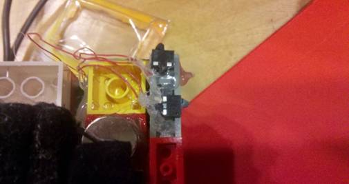
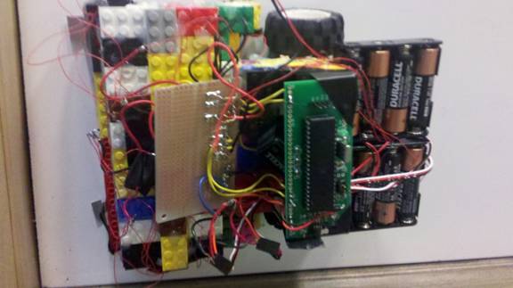
From our trial and error we define the following points on the chassis that needs a strong grip:
We needed a few magnets in the front side to keep the eraser down, but not so much that all the force is directed to the front. The back side, where the servo is attached, is where most of the force should go. The front side has a row of magnets that balances out the force of the magnets on the back so the chassis would not tilt back or forth too much, since the eraser causes the bot to be tilted. As seen in the picture, we glued every magnet with a large amount of glue, since the magnets snap off at the slightest weakness.
Ideally, the magnets are kept off from the surface of the board and the switches sweep on the surface. However, due to the strong force of the magnets, some magnets do stick slightly. The strong force of the magnet shown above is counteracted by the magnets on the other end of the chassis. Since there is a slight tilt to the chassis, the two ends counteract each others force.
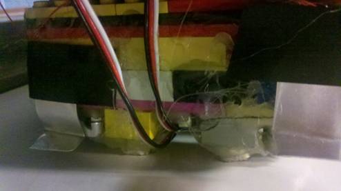
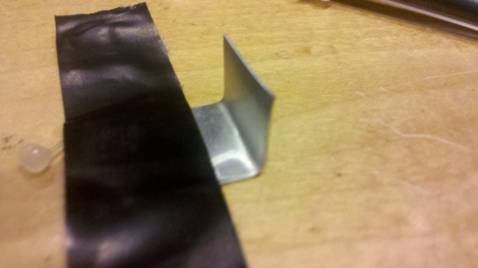
The bot has bumper sensors attached to all four sides. These sensors are simply micro switches that trigger an interrupt pin. The switches are all glued to the sides of chassis, near the surface of the board.
To provide a greater area of contact for the switches, we taped the followed aluminum strips in front of the switches. The strips are flexible and are kept a small distance from the switches. Its shape allows for the chassis to detect the lowest of board edges.
Finally, we enclosed the accelerometer on the middle of the chassis. Because we are using two single axis accelerometer, one of the accelerometer must be raised perpendicular to the other. We simply used lego to create a structure to support this, as shown below.
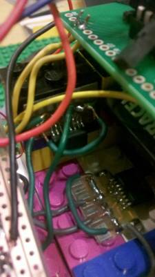
X and Y axis accelerometer
Hardware Design:
We had only three main components for the hardware: the servo motor, the accelerometer and the bumper switches.
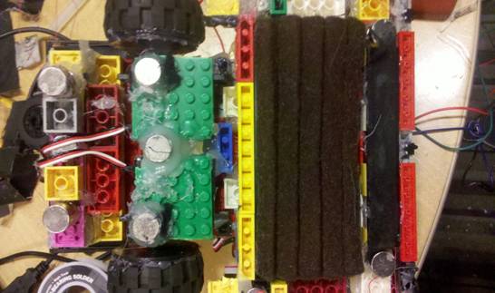
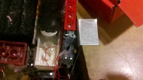
 A top
down view on the bot with view of the circuit, bumpers, board and servo
A top
down view on the bot with view of the circuit, bumpers, board and servo
Servo Motor:
We needed continuous servo motors for their ease of control and speed variability. At the same time we needed a servo motor with high enough torque to move the bot on board. It wasn’t feasible for us to calculate the torque we needed, especially since our chassis’s design was variable and had to be adjusted as we worked with it. Another issue was that the higher the torque value, the lower the speed we can get from the servo. We wanted the bot to move at a reasonable speed so many of the higher torque servos that we found online could not work. Additionally, continuous motors at such settings were even harder to find. In the end, our best option was a continuous servo provided by Sparkfun, which at 70 rev/min can get us a torque of 4.8 km-cm at 6 volts.
The servos were very easy to interface with, but they required an external 6volt source. We used two 6volt battery packs to power each servo and made sure that the protoboard and the battery packs shared a common ground. We also had to calibrate the servos so that they would rotate identically from the same signals. The signal for each servo came from pin B.3 and B.4 of the protoboard.
Accelerometer:
We originally planned to use Sparkfun’s digital I2C interface three axis accelerometer, but we could not get any value reading using the sample I2C code and after hours of testing believe the original accelerometers are no longer functional. Thus, we decided to use two single axis, 1.5G analog accelerometers. The accelerometers we used were the MMA1260D and the MMA2260D since they were the two models available in the lab. They are the same chip with different sense axis. The MMA1260D senses acceleration in the z (up and down with relation to the device), direction and the MMA2260D senses acceleration in the x (left and right, pin sides) direction. With the MMA2260D positioned on the bot with the sense direction front/back and the MMA1260D mounted perpendicularly so that it senses the left/right acceleration we were able to determine which was the bot was facing. Since we were only detecting the effects of gravity on the bot, 1.5G was sufficient. The bot was planned to undergo higher accelerations.
The accelerometers were analog outputs, so we input their outputs into the on-board analog to digital converters on pins A0 and A1. Since the atmega644 only has one ADC, we needed to toggle between the two pins each time we read the inputs. The accelerometers were read at an interval of about 100ms. This allowed a balance between collecting enough information to operate the sequence of commands and not wasting too much time collecting unneeded data.
The accelerometers output zero Gs as about 2.5V, which translated to ~127 on the 8-bit resolution ADC input. This means that the measurements centered around this value as “level” according to the accelerometers. Given that we had to glue the accelerometers to the lego chassis, they were not placed exactly parallel to the axis they were measuring. To correct this, we hooked the bot up to the UART and held it as level as we could determine in each direction. These gave us the different values we would use for each of the accelerometers while the bot was facing up, down, left, and right. Knowing these values, we created a tolerance of five (on the eight bit scale) that would define each direction to help the bot drive in a straight line.
Soldering the accelerometers caused us more than enough problems. The chips are SOIC packaging so we used two halve breakout boards since all the important pins are on the same side. For some reason, the lead wires we attached to the accelerometers broke a few times and needed replacement.
We borrowed a tiny snippet of code to toggle between the two different input pins from Skyler Schneider and Jack Ellsworth's USB Wireless Tilt Mouse project from spring 2010 (http://people.ece.cornell.edu/land/courses/ece4760/FinalProjects/s2010/ss868_jfe5/ss868_jfe5/index.html). That snippet is marked in the comments of the code.
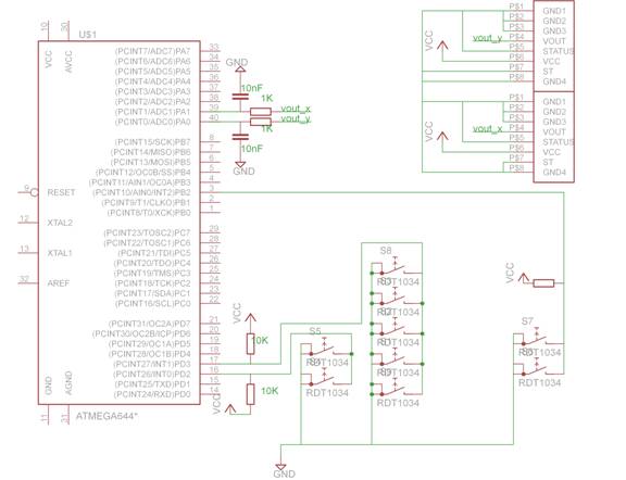
Bumpers:
The bot has one bumper on each side, but we only read three external interrupts. This is because that it is impossible for the bot to be in a situation where both the front and back bumpers are hitting at the same time. By keeping track of the bot’s orientation, we can deduce through code which bumper is hit when the front/back interrupt pin is triggered. The car has three bumpers in the front, and two bumpers on all other sides as shown in previous pictures.
All of the switches on one side of the bot are connected in parallel so that any of the switches getting triggered will cause a bump detection.
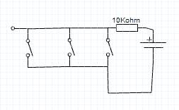
Circuit diagram for one interrupt pin
Program Design
The programming of the bot had several components that we divided up:
· Locomotion, the functions to execute all the proper movements
· Orientation, the functions to read off the accelerometer
· Sensing, the functions to read the bumper feedback
Locomotion:
The following table lists all of the possible moves of a two servo bot.
|
Movement |
Left servo |
Right servo |
|
Move Forward |
CCLKWISE |
CLKWISE |
|
Move Reverse |
CLKWISE |
CCLKWISE |
|
Turn left |
CCLKWISE |
CLKWISE |
|
Turn right |
CLKWISE |
CCLKWISE |
|
Pivot Left wheel forward |
CCLKWISE |
STOP |
|
Pivot Left wheel backward |
CLKWISE |
STOP |
|
Pivot right wheel forward |
STOP |
CLKWISE |
|
Pivot right wheel backward |
STOP |
CCLKWISE |
|
Stop |
STOP |
STOP |
We wrote individual functions for each one of the movements by setting the OCR0A and OCR0B to one of three values, which rotates the servo clockwise, counter clockwise or stops it. We created the PWM through timer 0 fast PWM mode by setting COM0A1, COM0B1, WGM00, WGM01 to 1. This setting means that the timer will clear OC0A on compare match and set OC0A at BOTTOM.
Since the chip generates a continuous PWM signal, the servos will run infinitely long. We needed some way of controlling the duration of the signal in the case of going straight, and a way to control angle in the case of turning and pivoting. To achieve this we implemented a system timer that kept track of the system run time by incrementing a time struct every milliseconds. The timer struct is as follows:
typedef struct {
unsigned int sec;
unsigned int msec;
} realtime_t;
We increment msec every milliseconds through timer 2 which enters the timer interrupt when the timer counts to 16 on OCR2A at 1/1024 prescaler. Every 1000 milliseconds we increment the second value. With this time counter, we can implement the following loop to have the servos reverse for a set period of time:
long int time_snap=time_to_ms(); //time_to_ms is the current time in ms
move_Reverse();
while(time_to_ms()<(time_snap+500)){
n=sprintf (buffer, "%d plus %d is %d", a, b, a+b);
} //wait till current time is *time* more than the snapshot time
What this code does is that at the instance that the bot starts reversing, we take a system snapshot of the current time. The while loops makes us wait till the current time is greater than the snapshot time plus some milliseconds. The sprintf inside the while loop keeps the code from skipping the while loop which it does strangely when there is nothing inside the loop.
For angle controlled rotation, we depend on the readings from the accelerometer. Whenever the accelerometer is oriented to up, down, left or right, a flag is set. By keeping track of this flag the bot can rotate from one orientation to another, 90 degrees at a time. For our application, a 90 degree minimum angle control is good enough. We would use a similar blocking method as with the time function:
void turn_Left_f(int face){
turn_Left();
while(facing != face){
printf("Turn left face %d, currently %d\n",face, facing);
}
}
The variable “facing” is a global variable that keeps track of the current orientation of the bot, as long as it doesn’t match the required direction, the bot will keep turning.
Aside from the conventional moves listed above, we also required the ability to perform a U-turn. The bot works by sweeping the board row by row, this requires that it performs a U-turn whenever it hits the side of the board. To do a U-turn, the bot reverses a bit, turns 90 degrees, reverses again and turns 90 degrees. The reversing provides additional room for the bot to turn and lessens the chance of getting stuck on the wall.
Finally, we wrote a function that resets (start_Over()) the bot to the top left corner. This algorithm does the following:
1. Rotate till facing down
2. Reverse till back bumpers hit
3. Turn leftwards to face the right side of board
4. Reverse till back bumpers hit
Orientation:
Do to the physical structure of this bot, it does not go in a straight line by itself. The weight is not balanced perfectly so when driving to the left or the right, the front of the bot tends to drop towards the ground. If we simply powered the wheels to go straight, the bot would end up driving in a diagonal line to the opposite lower corner of the board.
To correct this we used the accelerometers. In addition to know what direction the bot was facing, the accelerometers also let us determine how far away from the perfect angle we are. By setting a tolerance of five on either side of the inputted ADC value, we were able to maintain a measurement within about seven degrees on either side. If the bot dropped below this value or climbed above it, the necessary pivot function was called in order to attempt to return the bot to the desired direction.
For the alignment function to be called, the bot must be moving forward or in reverse. Obviously there is no alignment needed when turning. It then uses the given value of the desired direction to correct the bots positions. Typically the given direction, move_direction, is set in other functions, but it can also be set manually in order to extract preferred outcomes without needing to modify various functions.
When correcting position while driving forward, it was important that we used the pivot forward functions. This kept the bot going in a forward motion and therefore was constantly making progress towards the end goal. Had we used the reverse pivot functions while going forward, the bot would take much longer to travel from one side of the board to the other. Conversely, when traveling in reverse, the pivots need to be in the reverse direction for similar reasons as when traveling forward.
One important part of the algorithm is positioning the bot in the top left corner of the board, where the rest of the algorithm takes place. We do not require the user to place the bot in a particular place on the board and the can place it anywhere they like. To move the bot into position, we first turn the bot left until it has detected that it is facing down. Once it has done this, the bot begins reversing, climbing up the wall backwards. While doing this, the bot is also correcting it’s angle so that it climbs in a relatively straight line. The bot continues to climb the board until it reaches the top of the board and the rear bumpers are activated by the board’s edge. It then moves forward for 150 ms, which makes space for the boards left side and bumpers and rotates to face right. The bot then, again, backs up until the rear bumpers are activated. We now know we are in the top left corner, which is our starting position.
Sensing:
The bumper switches triggers pin D2, D3 and B2. These pins are external interrupts pins INT0, INT1, INT2 respectively. These interrupts are enabled by setting EIMSK, and EICRA sets all these pins to generate interrupts on rising edges, when the bumper first hits. Thus, we have three external interrupt vectors and for each interrupt handler we raise a flag to indicate that the bumper was pressed at one side. However, we needed a way for the flags to be cleared when the bumper is no longer touching. With the interrupts alone, the flags are never reset. To get around this we utilized the system time again and took a snapshot of the time every time the code entered the interrupt. Inside the timer 2 interrupt handler, we check every 100ms to see if there has not been an entry inside the bumper interrupt for half a second. If so, we can safely assume that the bumper is no longer touching.
During the runtime of our combined code, we noticed that when the bot reached a tight corner that it could not perform a U-turn on, it would get stuck going forward at an angle towards the bottom. To get around this, we modified the front bumper interrupt handler to reverse a bit every time the front bumper hits something while it is turning. This allows the bot to slowly get around tough corners since the interrupt only pauses the turning of the bot.
Results
Speed of Execution
Since the code was not processor intensive, the execution time primarily depended on the servo and chassis performance on the board. Because of the relatively slower speed of the bot’s movement, the code did not have to poll the sensor values as often, so the code speed was not a bottleneck at all. We polled the accelerometer and bumpers every 100ms. The bot moves at a slow pace across the board, especially when going upwards. Whenever it gets off orientation, the bot spends a bit of time pivoting before going forward. Pivoting takes the most time for the system since only one wheel moves and thus there is less torque to move the bot.
Accuracy
The accelerometer is not perfectly accurate so we had to have some threshold for reading its values. We found that a threshold of +/- 10 worked well since smaller thresholds didn’t do as well when the bot was rotating at higher speeds. With the accelerometer, the bot can move in a relatively straight line and can turn at pretty close to 90 degrees. On its U-turns, the bot also does a decent job. However, during testing sometimes the bot stop aligning itself, this is because the sometimes the metal flaps get bent and remains pressed against the switch even after collision. This is a physical flaw that can be mitigated but not completely prevented.
Safety and Interference
The only safety concern for the bot is that the strong force of the magnets could pinch a user’s hands if improperly handled.
Usability
Our product is easy to use, all it takes is a flip of a switch and the bot does the rest. For our bulky prototype however, the bot has an easier time when it is initially placed away from edges and corners.
Conclusion
We started the project expecting to spend a few days to get a working chassis, but it turned into a few weeks of testing various designs. In the end we spent a lot more time than planned for the chassis, that and complications with the accelerometer set us back quite a bit in time. Fortunately, the coding was more straightforward and didn’t take as much time. We had originally planned to implement an additional servo motor to pivot the eraser so that the bot erases the board as a human hand would. But time constraints kept us to just doing the simple resetting and sweeping function of the bot. Also, due to the issues that the eraser gave us, we could not afford to raise it too high, so the eraser itself can’t quite erase the board. However, by adding a wet wipe, we were able to wipe the board clean.
Next time we might pursue having electromagnets and lithium ion batteries. Due to timing constraints we didn’t have time to purchase lithium ion battery packs, which would’ve reduced our bot’s weight significantly. Electromagnets would be nice so that we would have a much more precise way to control the magnetic force of the chassis on the board. This, way instead of trial and error with magnetic configuration, we could simply turn on/off different arrays of electromagnets on the bottom of the bot. With such a setup we might even CAD a real chassis and machine it from aluminum. Having a structurally stable chassis with variable magnetic force, we would not have encountered as much mechanical issues as we did.
In terms of the code that we borrowed from others, we only used Bruce Land’s code templates for generating PWM signals and reading analog inputs. Everything else, including the cleaning algorithm, we came up with by ourselves.
Additionally, our TA mentioned the possibility of getting a patent from this product. But currently we are not sure if this can be possible or worth the trouble.
Ethical considerations
To conform to the IEEE code of ethics we want to make clear that our product and the process of creating it conform to the ethic standards. We worked together and helped others in the lab that had issues. We gave advice to our classmates that had issues and asked others when we had our own problems. When we faced the issue of not having a proper separate power source for our servos, another group suggested for us to simply tether the bot to a 6 volt source. We valued their advice and followed it till the chassis restructuring showed that the bot could handle having battery packs.
We made sure in the previous section to credit Bruce Land for his sample code, as per IEEE ethics to credit properly the contribution of others. In terms of safety we made sure to design a bot that secures tightly to the board and has little risk of falling and injuring anyone. Also we would like to warn all users of the bot to take care in removing attaching the bot, since the magnet is extremely strong and capable of causing major injuries to the fingers.
Appendix
Program Listing
long int time_to_ms(void):converts current time to milliseconds
void updateDir(): updates current orientation
void moveFlagReset(void): resets movement flags
void pivot_LF(): pivot left going forward
void pivot_RF(): pivot right going forward
void pivot_RR(): pivot left going reverse
void pivot_LR(): pivot right going reverse
void move_Forward(): move forward
void move_Forward_t(int time): move forward for time ms
void move_Reverse(): move reverse
void move_Reverse_t(int t): move reverse for t ms
void move_Left(): move left along board
void move_Right(): move right along board
void move_Up(): move up along board
void move_Down(): move down along board
void turn_Left(): turn left
void turn_Left_f(int face): turn until facing face
void turn_Right(): turn right
void turn_Right_f(int face): turn right until facing face
void align_straight(): aligns bot in its current orientation
void uturn(int direction): performs a U-turn either left or right
void start_Over():code to reset the bot to the top left corner
Schematics
Cost Details
|
Item |
Cost |
|
Lego parts |
$0 |
|
9 volt battery |
$2 |
|
2 six volt battery packs |
$8 |
|
Solder-board |
$2.50 |
|
Custom PC-board |
$4 |
|
Mega 644(sample) |
$0 |
|
sip or header socket/plug |
$0.50 |
|
DIP socket |
$0.50 |
|
2 continous servos |
$28 |
|
2 single axis-accelerometer |
$0 |
|
Micro-switches(6) |
$4.50 |
|
Neodynium magnets |
$0 |
|
total: |
$50 |
Task Division
|
Tasks |
Mike |
Le |
|
Chassis Construction |
+ |
+ |
|
Accelerometer |
+ |
|
|
Bumper |
|
+ |
|
Custom-PC board |
|
+ |
|
Parts ordering |
+ |
|
|
Circuit board soldering |
+ |
+ |
|
Coding |
+ |
+ |
References
Vendors: Sparkfun Electronics, DigiKey
Sample Code: ADCtestGCC644.c
Datasheets: Mega644 datasheet , Robotics with Boebot version 3.0