Touchscreen Chess
Samiul Nur
Caspar Valk
Introduction
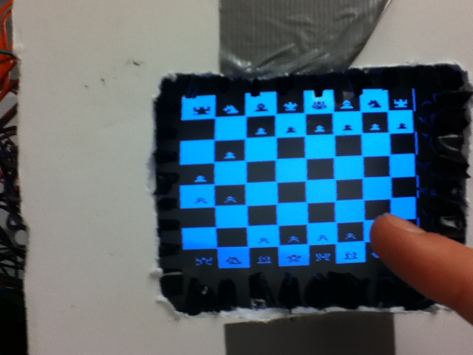
Our project is a two player touchscreen controlled speed chess game.
One of our goals for this project is to build a reliable touchscreen device. Our initial plan was to use an LCD and attach LED and phototransistors on opposite sides. However, we determined that most commercial LCDs are small and placing 8 LEDs/8 transistors on each sides is difficult and there could be a lot of interference between adjacent LCDs and transistors. Our instructor Bruce Land advised us to use a 6 inches diagonal TV and we found that we can actually place the LEDs and transistors with sizeable width between each LEDs/transistors so that interference is minimal. We were lucky to get access to video generation code from the ECE 4760 website which we used to generate the screen on the TV. We also used bitmaps to generate the graphical representation of the pieces. Over the process of 5 weeks, we actually made changes to our initial plans an design. For example we planned to tape the LEDs and transistors to the TV, but when we were not satisfied of the sturdiness and the accuracy of our touchscreen, we used a foamcore and used it as a base to put the LEDs and transistors on. This new design made our touchscreen more accurate. To make our device even more accurate and sturdy we taped the foam core to the TV.
We successfully implemented the first part of our proposal. We also planned to use a transceiver to transmit/receive data between two MCUs connected to TVs using which two users could play a wireless 2 -player game. However, due to shortage of time, we could not implement that feature. We did not have enough time to build the touch screen feature for another TV and to develop the wireless connection. Furthermore, our program uses a lot of data memory and we did not have enough memory in our MCU to properly interface with another MCU to run the two player game.
1. High-Level Design
1.1 Rationale and Sources of the Project Idea
Programming a relatively complicated game, such as chess, to be displayed on a TV would provide the opportunity to combine material covered in Microcontrollers (ECE 4760)—such as timing, concurrency, and general C programming for the ATMega644 microcontroller with GCC—with relevant material not covered in the course this semester—such as video generation. After discussing the proposal, the professor suggested that we add some significant hardware component that would require hardware-software interaction. As a result, we decided to develop a touchscreen chess game, which had substantial hardware and software components to it.
1.2 Background Math
The mathematics used in the touchscreen chess game software did not require any complex mathematics. Our program makes use of simple arithmetic to calculate valid moves for each individual chess piece. Furthermore, modulo and division operations allowed the program to determine the address of any particular chess tile based on the numerical address that we assigned to it.
1.3 Logical Structure
The logical structure of this project is to build a touchscreen and to run a game of chess on it. A user will be able to touch any of the chess tiles and thus block off infrared light to certain phototransistors, which would allow the microcontroller to compute which chess tile was selected. Once a chess tile is selected, the user would be able to select a different chess tile for the selected piece to move to. The software we program will concurrently continue updating the screen while running chess algorithm code to check whether desired move adheres to the rules of chess or not.
1.4 Hardware/Software Tradeoffs
The hardware is not as exact as we would hope: we count on the LEDs emitting reasonably straight beams of infrared light to the corresponding, opposite phototransistors and thus allowing these phototransistors to input voltage data into the MCU that would allow it to determine the chess tile selected. These LEDs and phototransistors are not perfectly directional, thus our design suffered from multiple LEDs shining infrared light diagonally into phototransistors even when the LED right opposite the phototransistor is blocked off. Nonetheless, this design made sense to us, and we found a reasonable solution to offset the issue.
In terms of software, our only real tradeoff was number of lines of code vs. efficiency of the code. In some cases, it would take the MCU less time to copy multiple large similar versions of code in divided if-statements than to incorporate these if-statements into one large such chunk of code.
1.5 Relationship of design to available IEEE, ISO, ANSI, DIN, and other standards
Our project is relatively safe considering we do not use any flammable or explosive material. Our touch screen interactive chess game should also be user friendly as humans like touch screen devices. We also did not make use of other people’s work without acknowledging them.
1.6 Existing Patents, Copyrights, and Trademarks relevant to the Project
As we only made use of “beer-ware,” student projects from previous years, and course material and advice provided by the TAs and the professor, we did not have to deal with any patents, copyrights, and trademarks.
2. Software Design
2.1 Initial Structs and Definitions
The complicated chess algorithms and interrupt service routines in our software require us to instantiate numerous variables, constants, and struts. location_piece refers to the location of the chess tile that the user has most recently touched on the touchscreen or is currently touching. old_location_piece refers to the location of the chess tile that the user has previously touched. Please see the Debouncing section of this report for a detailed explanation of loc_deb, loc_deb_count, and the #defined loc_deb_lim. The variable possible is 1 when the user has touched two chess tiles, such that the chess piece in the initial chess tile the chess piece in the first chess tile can legally move from old_location_piece to location_piece. If the user attempts a move that the rules of chess do not allow, the variable possible will become 0. start_move_x and start_move_y are respectively the x and y coordinate positions of the location of the piece selected by the user to be moved. stop_move_x and stop_move_y are respectively the x and y coordinate positions of the second tile selected by the user to move the chess piece to. We also initialize a series of chars that designate whether certain chess pieces have moved or not. For example, SolidKingHasMoved will be 1 when the solid king has made a move this game and will be 0 when the solid king has not yet moved this game. These variables are necessary to implement more complicated chess moves such as castling. The unsigned char choosePiece means that a piece has been chosen to move, and the unsigned char moveToDestination means that a location has been chosen for the chess piece to move to. The #defined value lineTime is the time required by the microcontroller to update all the lines on the TV that we are using. The #defined value sleepTime is the time we put the microcontroller to sleep. ScreenTop is the top line on the TV that the microcontroller prints to, and ScreenBot is the bottom line that the microcontroller prints to. We #define each different chess piece (on both sides) in order to easily be able to define them. Finally, LineCount is the line number in the current frame, and the screen array is used to designate how much memory we allocate to writing a certain set of graphics to the TV.
2.2 Debouncing
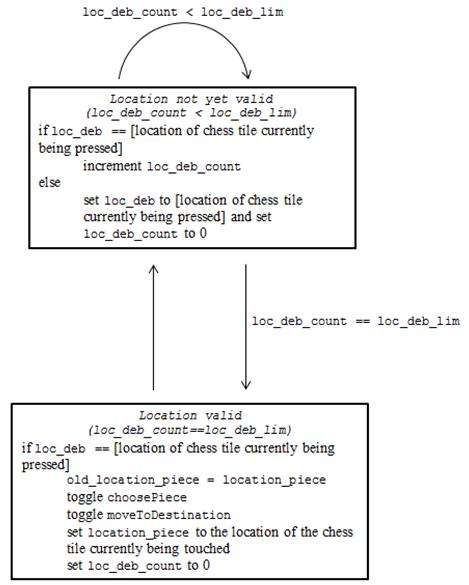
In order to debounce the selection of a particular chess tile, we instantiated unsigned chars loc_deb (location debounce) and loc_deb_count (location debounce count), and we #defined loc_deb_lim (location debounce limit) as 10. We always maintain the unsigned char variables location_piece, referring to the location of the chess tile that the user has most recently selected, and old_location_piece, referring to the location of the chess tile that the user has previously selected. As such, the user would select one of his/her chess pieces (the location of which would be stored in old_location_piece) and would then select an empty chess tile or a chess tile containing a chess piece belonging to the opponent (the location of which would be stored in location_piece), and the user’s chess piece would move from old_location_piece to location_piece. It is these two variables that are debounced: the first time the user selects a chess piece by touching the location of the piece’s chess tile on the touchscreen, loc_deb is set to a numeric constant between 0 and 63 (inclusive), corresponding to this location; for every cycle (approximately 1/60 of a second) that the user continues to touch this location, loc_deb_count is incremented; once loc_deb_count reaches loc_deb_limit (10), old_location_piece is set to location_piece and location_piece is set to loc_deb, as shown schematically in the figure below:
2.3 Timer Functionality and main() function
We made use of the professor’s video code on the course website in order to display graphics to the TV screen. We used the video generation code version that contains a timer 1 compare B interrupt in addition to the timer 1 compare A interrupt. The timer 1 compare A interrupt is the sync generator and raster generator. This interrupt basically runs through each scanline in pulses of every 5 microseconds. It is important to note that the timer 1 compare A interrupt has to be entered when the MCU is in sleep mode to accurately time the sync pulses and that no other tasks can be run when the MCU is in sleep mode. Thus, we use the timer 1 compare B interrupt to allocate as much time as possible to other tasks before we put the MCU into sleep mode. The timer 1 compare B interrupt actually activates interrupts (from inside the timer 1 compare B interrupt!) and puts the MCU to sleep soon before the screen needs to be updated (5 cycles is a good number). This way, the screen is updated; our tasks are executed after the last line at ScreenBot has been printed to the TV; next, the MCU enters sleep mode, and shortly thereafter it starts to print updated graphics to the TV again. This way, we achieve around 50% more efficiency than if we were to let the main() function to put the MCU to sleep, which is very useful when programming complicated tasks to run chess algorithms.
In our main function, we first call the function initialize() in order to set all timer 1 registers, and we run the function initializedLocation(). After that we enter a continuous while loop that stops only when the king on one of the sides is taken. In speed chess, the king can be taken, rather than have to be put in checkmate. Once one of the sides’ kings is taken, we will leave the “infinite” while loop and print the relevant victory measures.
2.4 Graphics Design
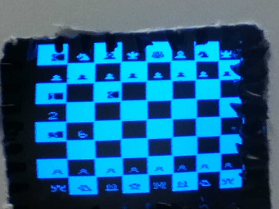
For our chessboard, we needed the graphical design of the chess pieces and the design of the chess board itself. The chessboard is an 8 by 8 board with alternating black and white squares. First we needed to create the board. To create the board, we used a function called video_line(). This function was actually copied from Bruce Land’s ball animation graphics code. Basically this function will draw a single line of a particular color from a pair of initial x, y coordinates to a pair of final x, y coordinates. We used this function inside nested while loops to generate the chess board boxes. We draw white lines next to each other with little separation between them so that they look like they compose a solid box ( since the resolution is not too high, a series of lines next to each other will look like a square of finite width ( the width of each box used here is 17 on the x direction and 20 on the y direction. We use another while loop to make sure that we generate lines for a fixed width and then do not draw lines for an equal width. This represents the black box. In this way we create an 8 by 8 chess board of alternating black and white boxes.
To generate the chess pieces we had to create bitmaps. From Bruce Land’s ball animation code, we inherited a set of bitmaps for ascii characters which are present in a 128 by 7 array. Since ascii characters do not have any characters associated with the numbers 0 to 31, we figured that we can use the first 24 ascii numbers to represent the different type of chess pieces (in Bruce land’s code the bitmaps for those ascii numbers were all 0’s so would represent a white block). We used 4 bitmaps for rooks, 4 for King, 4 for queen, 4 for Pawns, 4 for Knights and 4 for bishops. This is because in the screen, we cannot identify a black piece on a black tile, a white piece on a white tile etc. So we declare the teams as a hollow team and a solid team. A solid piece will be a solid white piece on a black tile and a solid black tile on a white piece. On the other hand, a hollow piece will be a hollow white piece on a black tile and a hollow black piece on a black tile. The representations of some of these pieces are given below so that we can comprehend the differences between them.
We implemented some functions to plot the characters and the lines. We will go over it in some detail in this section.
video_pt( char x, char y, char c) This function takes the value of the coordinates in which to plot a point. 18 bytes are required to plot points along an entire line. A black point is plotted if the last parameter is set to 0. A white colored point is plotted if the last parameter is 1. We can draw upto 500 points in one frame time.
video_line (char x1, char y1, char x1, char x2, char c) This function will draw a line into video memory. The line extends from (x1,y1) to (x2,y2) with a color as above. It uses a Breshenham algorithm to generate lines at high speed. We can draw about 500 points worth of lines in one frame time.
video_putchar( char x, char y, char c) This function can be used to draw an 8x7 character at (x,y) with ascii characters which are contained in an array called ascii. The coordinates represent the upper-left corner of the character. We can draw about 16 8x7 characters in one frame time. Even though this function was inherited from Bruce Land's ball animation generation code, we modified the code so that we can draw an 8x7 character instead of a 5x7 character. This change enabled us to implemented the fully formed bitmaps of each of the character pieces. Since the first 31 ascii characters' bitmaps represent blanks, we replaced the first 24 with bitmaps of the chesspieces. Thus we used video_putchar function to draw the chess pieces.
video_smallchar(char x, char y, char c) Draw a 3x5 character at (x,y) with character number c. The x coordinate must be divisible by 4. The coordinates represent the upper-left corner of the character. We can draw about 200 3x5 characters in one frame time.
video_puts(char x, char y, char *str) Draw a 5x7 string starting at (x,y). The coordinates represent the upper-left corner of the first character. We can draw about 16 5x7 characters in one frame time. void
video_putsmalls(char x, char y, char *str) This function will draw a 3x5 string starting at (x,y). The x coordinate must be divisible by 4. The coordinates represent the upper-left corner of the first character. We can draw about 100 3x5 characters in one frame time.
To create the screen, we use the video_pt function which sends 18 bytes per line. We use two variables to determine the size of the screen. ScreenBot is defined as 200 and ScreenTop is defined as 30. The difference between them is 170 and since we are sending 18 bytes per line, the product is 3060, which is assigned as the size of the array called screen. We found that using these values of ScreenTop and ScreenBot gives us the right size and resolution as we would like. We used a larger size of the screen array at first but that would take more memory and introduce more flicker in the screen. 3060 as the size of the array seemed to compensate for memory and resolution very well.
Checking for allowed moves
We used speed chess rules to create our algorithms. We implemented a function callled isMovePossible which is called in task1. This function takes in 2 unsigned character parameters. When we call the function, we send the old_location_piece and the location_piece parameters. These 2 variables are assigned in the touch recognition code and are integers from 0 to 63 representing each chess piece starting from top left of the chess grid. However these 2 variables are initialized as 251 and 250 before a touch is detected. This is to avoid using these 2 variables when the user is yet to touch the screen. isMovePossible function returns a 1 if a move is possible and returns a 0 if a move is not possible.
We determine the x and y values of the piece by using the mod and division operations respectively. Basically, if we perform a mod by 8 operation on location_piece value, we get the x coordinate value and performing a division operation would give us the y coordinate value (since we are using characters, we are just flooring the quotient). We assign x1, y1 as the x and y coordinates of old_location_piece and x2, y2 as the x and y coordinates of location_piece.
At first the function checks for some conditions to see if it could deem it impossible to make a move without even checking for possible chess moves. The conditions it considers are as follows
1. If old_location_piece has a value of 251. This means old_location piece did not get a value of a tile in the chess grid yet.
2. If location_piece has a value of 250. This means location_piece did not get a value of a tile in the chess grid yet.
3. If old_location_piece has a value of 250. Since we assign the value of location piece to old_location_piece, in some cases it could be that old_location_piece got the initial value of location_piece (ie 250) assigned to it. This value does not represent a particular chess tile either.
4. If it is the solid team's turn and the user presses on tile containing another solid team piece or if it is the hollow team's turn and the user presses on a tile containing another hollow team piece.
If none of these conditions are met, we use our knowledge of chess to determine the moves. To identify a particular piece we check to see if its location is equal to the old_ location_piece value. We implement each of our structs for this purpose. So for example if SP1.location is equal to old_location_piece, we know that the tile which was selected at first was the location of a pawn. Since we initialized each chess piece as an instance of a struct we can check each one's location. We first go over the moves of solid pieces so we have an if statement encompassing all the code within it with the condition turn==0 since it would represent that it is the solid's turn to make a move.
An array called tileboard was initialized as a global character array. This is an 8 by 8 array which contains a 1 for the chess grid piece if it is occupied by a solid piece, a 2 if the tile is occupied by a hollow piece and a 0 if the tile is unoccupied. This array is initialized as having 1's in the first 2 rows and 0's in the next four and 2's in the last 2 rows. Every time a chess piece moves, we update this array. Thus we can keep track of every tile to know what they contain. We had some issues at first when we swapped the columns with the rows as we thought that the row number is the same as the x value and the column number is the same as the y values. However after debugging for some time and getting erroneous allowable moves, we figured that we need to switch the x index with the y index to make corrections.
We have a code block for all pawns within an if statement since all pawns have the same allowable moves. We check to see if the pawn moves a tile towards its opponent piece (down for solid pawns and up for hollow pawns). We also check to see if the pawn makes its first move because then it can actually move two tiles towards its opponent piece. We can just check the current location of the pawn to see if it is equal to the initial location (all initial locations are assigned in the initializelocation() function).
We then have a code block for knights. Since knights can move 2.5 steps in any direction we check if the absolute difference between initial and final x and initial and final y values are 1 and 2 and vice verse. This would mean that any move that means that the knight moved 2 steps in an x direction and 1 step in a y direction or 1 step in an x direction and 2 steps in a y direction is allowed as long as a piece of the same team is not present on destination tile. Since we rule off any chance of allowing a piece to move on a location currently occupied by another piece of the same team, we do not have to check for that criteria again.
Next, we determine the king's allowed moves.
if((-1 <= (x1-x2)) && (1 >= (x1-x2)) && (-1 <= (y1-y2)) && (1 >= (y1-y2)))
The above if statement will check to see if the King moved to an adjacent tile. Since King can move to a tile as long as it is adjacent, this move is allowed. We also keep track if the king has moved or not. This is because we implemented the feature for castling which is only allowed if King has not moved and the rook involved in the castling has not moved either. So we also need to keep track if the rook made its first movement or not. Castling also needs that the tiles in between the rook and the king are empty, something which we can check using our tileboard array.
The queen and the bishop's movements are checked in one code block and the rook and the bishop's movements are check in another code block. Since the bishop can move diagonally in any direction, coding for possible moves was simple. However we had to make sure that there are no pieces on the way. This was a challenge, but we used a loop through the movements in the x and y coordinates and incremented/decremented the x and y values together to see if there is a tile with a piece on a particular x and y value. Since the bishop can move in 4 different directions diagonally, we had to code for increment in x and increment in y, increment in x and decrement in y, decrement in x and increment piece on a particular x and y value. Since the bishop can move in 4 different directions diagonally, we had to code for increment in x and increment in y, increment in x and decrement in y, decrement in x and increment in and finally decrement in x and decrement in y. A similar approach was used to code for the allowable movement for the rook. In this case we increment and decrement x and keep y constant and vice verse.
Then we coded for condition of the turn value being 1 ie it is the hollow team's turn to move a piece. This section was coded similarly to how we coded for the solid team. However we used different structs when identifying a piece eg HR1 for hollow rook 1 instead of SR1 for solid rook 1. We also had to make some changes to some locations which needs to be hardcoded for each team. For example when castling, we need to check if the tile where the queen and the bishop initially located is empty or not. These tiles' locations were hardcoded for the solid team castling as well as the hollow team castling.
Kill moves
When a piece kills another piece of the opposite team, we needed to ensure that the killed piece is not located in the board. The following extract of code ensures that if the hollow rook 1 has been killed, it does not stay in the board.
if (turn==0) //solid
begin
if (location_piece== HR1.location)
begin
HR1.location=-5;
end
Since we determined it is solid's turn with the if ( turn==0) statement, we know that the hollow rook must have been taken. In that case we set the location of that piece to -5 which means it does not exist on the board. We assign any taken piece's location to be -5.
Update graphics when a piece moves
In task 1 , after we determined if a particular move is possible or not, if it is possible, we need to make the necessary update in graphics. We have a block of code for every chess piece which has if statements checking if the old_location_piece was a particular piece. The location of the particular piece that existed in the old_location_piece is now going to be assigned the value of the new_location_piece. Next we update the graphics. As is previously stated, each of these pieces have a different look in different colored tiles. A solid rook has a different bitmap when it is located in a white tile or in a black tile. So we need to know if the location piece consists of a black or a white tile. We determine the color of a particular tile by calling a function getTileColor(char) which returns a 1 for white tile and a 0 for black tile. By inspecting the chess board and the fact that the chess tiles' colors alternate in the same row or column, we determined that we can use simple arithmetical calculations to determined the color of the tile. For example, if the row and column numbers of the tile are both even it is a white tile. There are three other conditions for combinations of odd and even numbered rows and columns.
After we determined what color the destination tile is we can draw a the particular bitmap needed on the location of the piece. We use #define statements to identify each of the bitmaps easily. For example mapHollowBishopWhiteTile is the bitmap of the hollow bishop on a white tile. Since the current tile which is occupied by the bishop before the move needs to be emptied out, we just draw a white tile if the tile is white and a black tile if the tile is black. Thus it has the effect of emptying out that tile.
One challenge posed was how to locate each of those tiles to use the video_putchar function which needs x and y coordinates as defined by the screen width and height. Since the amount of data memory available was low we determined that we could use program memory to keep an array/lookup table of the coordinates of each piece. We hardcoded each of the coordinates in the array. This array is called boardloc and we implemented the array entries as the coordinates of the positions we put the bitmaps on.
if (old_location_piece==HB2.location)
begin
HB2.location=location_piece;
if (getTileColor(location_piece)==1)
begin //white tile
video_putchar(boardloc[location_piece][0],boardloc[location_piece][1],mapHollowBishopWhiteTile);
if(getTileColor(old_location_piece)==1)
begin //old location was white
video_putchar(boardloc[old_location_piece][0],boardloc[old_location_piece][1],mapWhiteTile);
end
else begin //black
video_putchar(boardloc[old_location_piece][0],boardloc[old_location_piece][1],mapBlackTile);
end
end
3. Hardware Design
3.1 Touchscreen
Most of the hardware of this project, albeit simple and easy to understand, is extensive and tedious to build. We used the basic design of lab 4 of a phototransistor’s reaction to infrared light (and the absence thereof):

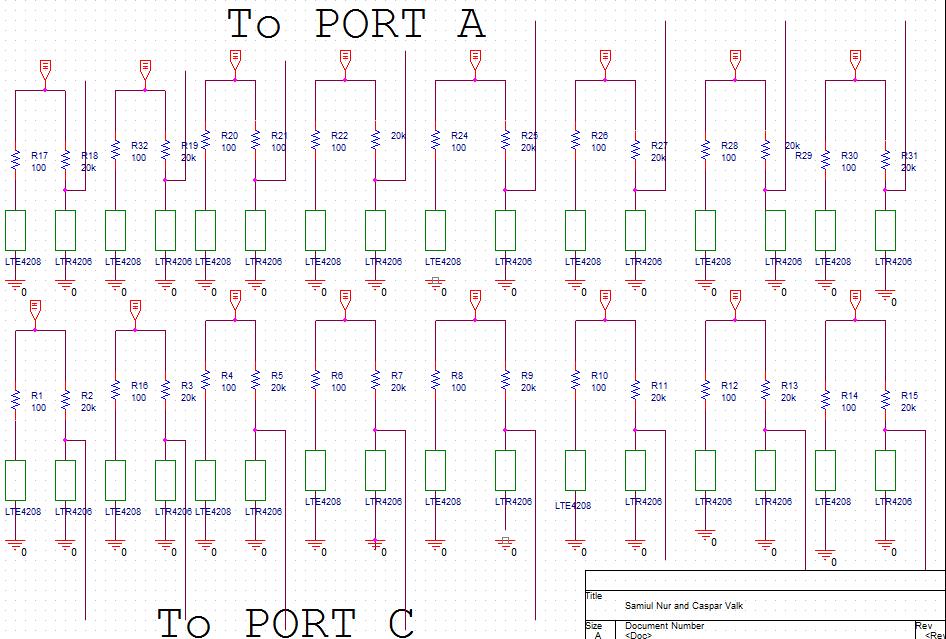
In this design, an LTE4208 infrared LED light shines on an LTR4206 phototransistor, causing the phototransistor to act similar to a short circuit and causing a voltage difference of close to 5 V over the 20 kilo-ohm resistor. The 5 V is the Vcc of the microcontroller, and the ground in the diagram is the microcontroller’s ground. The lead going to the MCU would nominally be grounded (in reality it would read a negligible 17 millivolts). Conversely, when infrared light to the phototransistor is blocked off completely, the phototransistor will act similar to an open circuit and will thus cause the lead to the MCU to remain at 5 V. Note, in our design, we replaced the 100 ohm resistor to the LED with a 333 ohm resistor.
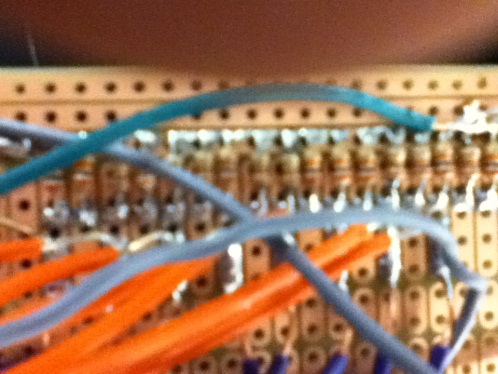
We applied this design to our project to serve as a touchscreen by fastening 8 infrared LED lights at the bottom of our TV pointing upward and 8 phototransistors at the top of our TV pointing downward and by also fastening 8 infrared LED lights on the right of our TV pointing to the left and 8 phototransistors on the left of our TV pointing to the right. This would result in a total of 16 LED-phototransistor pairs as shown in the diagram above and therefore 16 inputs to the MCU. As a result, we made use of 4 thin breadboards, to which we soldered the relevant resistors and wires for the top phototransistors, the LEDs on the right, the bottom LEDs, and the phototransistors on the left, respectively:
Thus, when a user would touch a chess tile on the TV screen, he/she would block off the infrared light from one of the bottom LEDs to on the top phototransistors and would block off the infrared light from on the LEDs on the right of the TV to one of the phototransistors on the left of the TV. If executed perfectly, 1 of the leads coming from the phototransistors at the top of the TV would be close to 5 V (the other 7 top phototransistors should be close to 0 V), and 1 of the leads coming from the phototransistors on the left of the TV would be close to 5 V (the other 7 phototransistors on the left should be close to 0 V). Using this information, the microcontroller would be able to determine which chess tile was selected.
In order to keep our software as simple as possible and our hardware cost as low as possible, we planned to input the leads from the phototransistors directly into ports A (top phototransistors) and port C (phototransistors on the left) as digital inputs. This would only work if the “high” inputs are close enough to 5 V (read: far enough above 2.5 V) and if the “low” inputs are close enough to 0 V (read: far enough below 0 V). Since the infrared light beams of the LED lights are not perfectly directional, but rather shine light outward in a conical shape, we had to limit the light from LEDs other than the corresponding LED from reaching a given phototransistor. If we did not steps to counteract this effect, light would shine into a phototransistor diagonally from LEDs other than the one that is blocked off by the user’s finger. We cut 32 pieces of black electrical tape and cut very small holes in the centers of these pieces of tape. Then, we placed a piece of tape on each LED and on each phototransistor, such that only the front tip of each respective LED and phototransistor would show through the small hole in the black electrical tape, thus minimizing the infrared light shining out of the LEDs diagonally and likewise minimizing the infrared light reaching the phototransistor from a diagonal direction.
3.2 Protoboard
We made our own protoboard for this lab to decrease costs and to gain some experience with hardware development. The professor gave us an empty board:
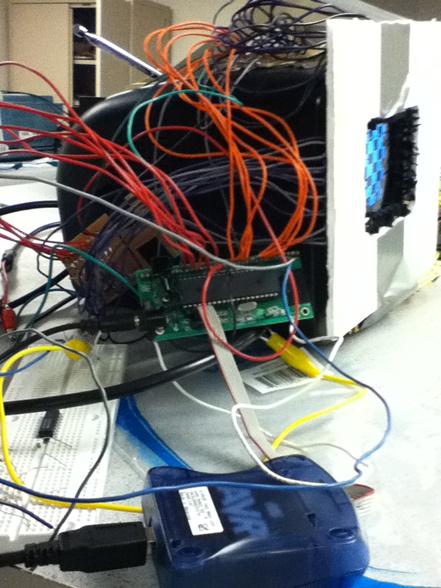
on which we soldered the relevant capacitors, resistors, crystal, regulator, etc. until it turned into the functional protoboard shown in the picture below:

Now, since our Vcc was running 16 different LEDs, each of which was demanding, the regulator advocated in the protoboard-building instructions on the course website could only handle a maximum of 100 micro-amps. Therefore, we removed this regulator and, put in place a 1 A regulator instead. Another side-effect of running so much hardware using the microcontroller’s Vcc is that the regulator gets really hot. To alleviate some of heat dissipated in the regulator, we slipped a heat sink on the regulator:

3.3 Hardware-TV Input
We use a TV as the base for the touchscreen as well as to show the chess board so that the two players could see the pieces and the board and play the game. To connect the TV to the ATMega644 micro controller, we needed to interface the video in port of the TV through a circuit as shown below.

As you can see, PORT D5 and PORT D6 are connected to the TV via 300 Ω and a 1kΩ respectively and a 75 Ω is connected to the two resistors, the TV video input and the ground.
Two bits of a port are used to generate three video levels:
4. Results
4.1 Speed of execution
Our software takes considerably longer to build than smaller programs that we ran over the course of our lab. This is because we use a lot of our memory. Even after trying to reduce memory usage as much as possible, by using program memory instead of data memory, we still use 91% of our memory. The graphics generation takes about 80% of the memory used. When the user touches a tile, then we get some flickering in the screen. This is because the interrupt that causes task 1 to run causes some disturbance in the speed of the execution of the graphics code. This causes the screen to flicker for a bit.
The touch screen is fairly sensitive to touches. One thing to keep in consideration is that the touching device needs to be a little thicker if the user touches the screen at a point which is further away from the phototransistors than at a point which is closer to the photo transistors. For a further away phototransistor, a tip with a larger cross sectional area would be needed to block the IR as light would spread out and cause interference with the LEDs. The hardware section goes over in detail in the approach we used to minimize interference from other LEDs.
4.2 Design conforming to applicable standards
Our design is consistent with the safety, health and welfare of the public. No part of the electronic device is prone to causing damage to users. My lab partner and I also ensured we do not use someone else's work without permission/ without properly crediting for his contributions. Our design comprises with all of IEEE code of ethics and standards
Our design maintains ISO standards for electrical engineering and electronics in general; including but not limited to standards of the following: voltages, general electrical terminology, safety, fire hazard testing, electrical wires and cables, integrated circuits and radio-communications.
5. Conclusions
We are satisfied with our results. We basically tested three features of our software and hardware in a broad way. First we tested our touchscreen and determined that the phototransistors are correctly functioning. We then wrote software to test if we can correctly interface the software with the hardware. Then our next step was to test each of the chess pieces and see if they were functioning correctly. Finally we tested if our graphics code was working correctly and the graphical representation of the chess pieces were working fine.
Next time we could actually try to use more LEDs per screen and thus construct a more accurate touchscreen. Two downsides of that is that we will need to make our software more complicated and we would need a larger screen so that there is enough space for the extra LEDs/phototransistors. Since we found that the sensitiveness of the touch decreases as we touch a part further away from the phototransistor, it might not be a great idea to use a bigger screen.
We would like to acknowledge consulting and using parts of software from a few different sources. First we used Bruce Land's video generation code (hyperlink) to implement the graphics in our screen. We also used the exact bitmaps as used by a project Remote Chess (hyperlink) . We consulted their IsMovePossible function and determined the different moves we would need and a general idea in how to implement them in our code. We also named some of our variables as they were named on the project.
6. Ethical Considerations and IEEE code of ethics
Our project fulfills all the IEEE code of ethics. Our project does not have any safety our security issues involved. The device will not injure anyone as long as it is handled properly. It also does not transmit any data via the radio so there could be no problems with transmitting data at a frequency which might interfere with some other data.
Our documentation is consistent with our actual device. We do not give incorrect information about the performance of our device. We have documented results using actual data from experiments and testing and we have been realistic about our observations. We do not falsify any experimental data, functionality, cost details of hardware etc. We have ensured that we do not perform a task which we are not qualified for, or which could pose safety issues to us. We have considered any safety issues that might be involved (eg wearing goggles when soldering). We acknowledged the contributions of other projects and work both in this report and also as commented headlines in our software for any parts of code or any idea implemented in our project. Finally, we build the touchscreen controlled chess game as a prototype, we do not intend to actually patent or publish our project. There are commercial touchscreen enabled games in the market.
6.1 Legal Considerations
We did not implement a transmitter in our project so we did not have to have to comply with any FCC regulations. Our project did not have any other legal issues either. Building our project is completely allowable by law.
7. Task Division
7.1 Specific tasks carried out by Samiul
Contributed in developing the software. Wrote parts of code related to touchscreen sensitivity, update graphics and creating and implementing data structures.
Build parts of the protoboard.
Helped in debugging software.
Contribution in Final Report.
Contribution to developing website.
7.2 Specific tasks carried out by Caspar
Built parts of protoboard
Built breadboards and soldered LEDs and phototransistors
Hot glued LEDs and phototransistors to foamcore and fastened contraption to TV
Wrote debouncing code
Integrated timer code
Helped in debugging software
Contributed to final report
Contributed to developing website
9. APPENDIX
9.1 Schematic
9.2 Cost Budget
Parts |
Source |
Unit Price |
Quantity |
Total Price |
ATMega644 |
Lab |
$6.00 |
1 |
$6.00 |
Custom PC board |
Lab |
$4.00 |
1 |
$4.00 |
LTE4208 LED |
Digikey |
$0.00 |
16 |
$0.00 |
LTE4206 Phototransistor |
Digikey |
$0.00 |
16 |
$0.00 |
Resistor |
Lab |
$0.00 |
variable |
$0.00 |
Capacitor |
Lab |
$0.00 |
variable |
$0.00 |
B/W TV |
Lab |
$5.00 |
1 |
$5.00 |
Foamcore |
Cornell Store |
$2.69 |
1 |
$2.69 |
White board |
Lab |
$6.00 |
1 |
$6.00 |
Thin Breadboard |
Lab |
$1.00 |
4 |
$4.00 |
Total |
|
|
|
$27.69 |
9.3 Additional Pictures

9.4 Code
Our code can be found here.
10. References
10.1 Data Sheets
ATMega644 datasheet
LTE4208 datasheet
LTR4206 datasheet
10.2 Vendor sites
Digikey
Cornell Store
10.3 Code/designs borrowed from others
We consulted and used parts of the graphics and chess functionality software
of the following ECE 4760 (formerly ECE 476) final project groups:
"Remote Chess" Spring, 2008
Erik Jarva
eaj24@cornell.edu
William Baughman
wpb3@cornell.edu
In addition, we received help and advice from the Spring, 2012 TAs and
from Professor Bruce Land. We used the graphics functionality that can
be found on the ECE 4760 course website:
http://people.ece.cornell.edu/land/courses/ece4760/video/videoGCC/UARTvideo/video_192x150_20MHz_uart_GCC644.c