Cornell University ECE4760
Infrared Communications
for Atmel Mega644/1284 microcontrollers
Introduction
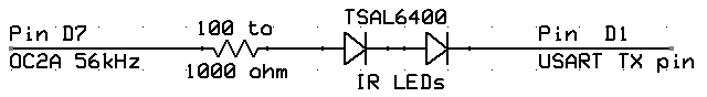
Infrared (IR) can be used for line-of-sight communications over low to moderate range. IR is nice because of the lack of interference (except for sun and compact fluroscent lights) and freedom from FCC regulation. The web site http://tthheessiiss.wordpress.com/2009/08/05/dirt-cheap-wireless/ (Jacob Sikker Remin, 2009) shows how to use a IR remote control receiver and IR LED to send ASCII serial data in a simple, but unreliable, fashion with no error control, packetizing, or other overhead. The transmitter drive uses a clever method to modulate and invert the serial output from the USART transmitter. The circuit is shown below. In my version, MCU timer 2 is used standalone to generate a 56 KHz square wave on pin D7. A lower resistor gives more range, but of course draws more current. The TSAL6400 can take 100 mA forward current, but the maximum current rating for any port pin of the MCU is 40 mA. You should probably limit the current to 30 mA. At 30 mA, the forward voltage drop of the diode is about 1.25 volts, so the the resistor (with two diodes in series) needs to be
(2.5 volt)/(0.03 amp)> 83 ohms.
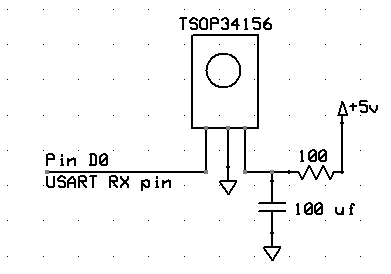
I improved Remin's protocol by setting up the link software so that timing constraints on the IR receiver AGC were guaranteed to be met. It turns out that there are several types of IR reciever, some of which are better at short data bursts, while others are better for sustained data. I chose a Vishay TSOP34156 for its good sustained data characteristics, minimal burst timing requirements, and reasonable data rate. The system I build works solidly at 4800 baud over IR with 5 characters of overhead/packet (start token, transmitter number, 2 char checksum , end token). It works with increasing packet loss up to 9000 baud. The receiver circuit is shown to the left. The RC circuit acts a low-pass filter on the power to surpress spike noise and improve receiver performance. The RC circuit should be close to the receiver. The range with a 100 ohm resistor is at least 3 meters with the transmitter roughly pointing at the receiver, and a packet loss of less then 0.1 percent. To manage burst length limitations there is a short pause between characters, and only 7-bit characters are sent, with two stop bits. The 7-bit limit means that you can send all of the printing characters on the US keyboard, but no extended ASCII. All data is therefore sent as printable strings, NOT as raw hexidecimal.
Packet Format and error codes
A packet consists of :
- A start character, which defaults to '#', but can be changed with a define directive.
No other character in the packet is allowed to match the start character.
- A one-character transmitter id number which the receiver will check against a number it expects, when using
ir_rec_packet.
The transmitter id should be in the ASCII character range '0' to 'z' (ASCII 0x30 to 0x7a, excluding the two start/stop characters).
The ir_rec_packet routine will return error code 3 if the id does not match.
The routine ir_rec_any_packet does not check the transmitter id, but returns the transmitter id (>=0x30) if the packet is valid and an error code if it is not valid.
- An arbitrary length, printable string (ASCII codes 0x20 to 0x7f, excluding the two start/stop characters), which of course, must fit into the size of the defined transmit/receive buffers.
- A one character checksum, which is calculated as the bitwise XOR of all the characters in the packet payload. The checksum is actually transmitted as two 4-bit values in the low 4 bits, ORed with 0x10 to form two 7-bit characters. This seemingly roundabout encoding was necessary to avoid burst length problems. A checksum mismatch will result in error code 4.
- An end character, which defaults to '%', but can be changed with a define directive.
No other character in the packet is allowed to match the end character.
- The receiving functions do not block, but just grab what is asynchronously built in the receive buffer.
An inconplete or missing packet at the time the receive function is called will result in error code 1.
- A buffer overrun will result in error code 2.
Programs for Mega1284
- The loopback test program is cleaner than for the mega644 (below) because the mega1284 has two USARTS. One USART is used for IR, the other for PC communication. I also added a routine to accept a message from any transmitter and cleaned up buffer length calculations in the receive routines.This version transmits on channel
T, but receives on any channel. The program assumes that the transmitter and receiver are connected as shown above, and pin D3 is connected to the line which sends data to the PC. You need to point the LEDs at the receiver, or put them side-by-side and use a reflector to bounce light back. The transmit and receive tasks are running at different rates. The transmit task formats a string containing time, task-count and error-count, then sends it. The receive task gets a packet, then either prints the transmitter ID and payload (if the return code indicates good data), or for testing, prints the nonzero return error code and the (possibly) corrupted packet. The timer 0 interrupt service routine manages the full duplex IR link. At 4800 baud, this program puts about 430 characters/second across the IR link. Bigger packets are more efficient in a low noise environment. You could expect a maximum transmit rate of about 20 packets/sec with about 20 payload characters/packet.
- A two processor link (base code, echo code)was built with the following characteristics:
- The base processor sends a time and packet number unless a button is pressed. If the button is pressed it sends 'zz'.
If valid, data received is sent to the puTTY window on the PC with echo= prepended,
If invalid, it
is sent to the puTTY window on the PC with an error code prepended.
- The echo processor sends back the packet it receives. If the packet is 'zz', then the echo processor zeros it's own time counter.
If no packet is received then the current time counter is sent back to the base formated as "RemoteTime=xxxx", where xxxx is in milliseconds.
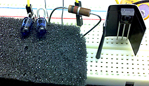
Note that to get good operation you must protect each receiver from the IR coming from its own transmitter. As shown below, putting the receiver in a protective, black tape barrier helps. You may need to put black material below the transmitter LEDs to reduce scatter from the whiteboard.
Programs for Mega644
- The loopback test program works in full duplex mode to send a message to itself. The program assumes that the transmitter and receiver are connected as shown above, and that in D3 is connected to the line which sends data to the PC. You need to point the LEDs at the receiver, or put them side-by-side and use a reflector to bounce light back. The transmit and receive tasks are running at different rates. The transmit task just formats a string and sends it. The receive task gets a packet, then either prints it (if the return code indicates good data), or for testing, prints the nonzero return code and the corrupted packet. The hardware USART is used for the IR link, so I wrote a software UART for communication with the human at the PC. Note that on the atmega1284 this software UART is not necessary, because the 1284 has two USARTs. The software UART routines
aux_getchar and aux_putchar allow use of fprintf and fscanf functions, but are blocking and should only be used for testing or when MCU load is light. The timer 0 interrupt service routine manages the full duplex IR link. At 4800 baud, this program puts about 430 characters/second across the IR link. Bigger packets are more efficient in a low noise environment. You could expect a maximum transmit rate of about 20 packets/sec with about 20 characters/packet.
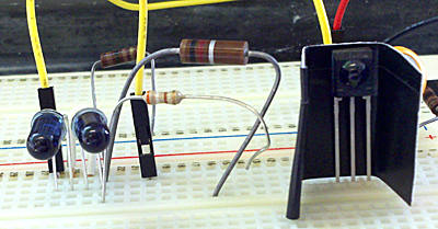
- A two-processor link was built with one processor running a version of the loopback code, but transmitting on ID=1 and receiving on ID=2. The other processor is running an echo code, receiving on ID=1, and if the data is valid, echoing the packet back out on channel ID=2. Using this code, it is necessary to put an IR barrier (electrical tape or metal) between the LED emitter and reciever on each processor. I think this is because the light scattering from nearby LEDs sets the AGC of the receiver too high to receive the remote LED output. In the image below, you can see the IR shield around the reciever, the two LEDs at the left, and the 100 ohm resistor in series with the LEDs.
- With both transmit resistors set to 1Kohm (implying
current=(2.5 volt)/(1000 ohm)=2.5 mA), and a range of 1 meter, the packet lose is about 1/1000.
- With both transmit resistors set to 390 ohm (implying
current=(2.5 volt)/(390 ohm)=6 mA), and a range of 3 meters, the packet lose is about 1/10 and is very dependent on scattering and reflections from the full duplex base transmitter to the base receiver, both of which are active at the same time. Room illumination was bright, indirect sunlight, plus 60 Hz fluroscent lighting.
- With the base station resistor set to 390 ohms and the echo station resistor set to 100 ohms, the packet lose is about 1/1000 at 3 meters range.
- A two processor link (base code, echo code)was built with the following characteristics:
- The base processor sends a time and packet number unless a button is pressed. If the button is pressed it sends 'zz'.
If valid, data received is sent to the puTTY window on the PC, and has an error code prepended if invalid.
- The echo processor sends back the packet it receives. If the packet is 'zz', then the echo processor zeros it's own time counter.
If no packet is received (before receive timeout expires) then the current time counter is sent back to the base formated at "RemoteTime=xxxx", where xxxx is in milliseconds.
The error rate seems to be <1/1000 packets at 3 meters with same resistors as above (condition 3, example 2). With sunlight shining directly (through heat-film covered window) onto the base receiver lens, between half and 90% of the packets are lost with 3 meter range, and 100 ohms on the echo transmitter LED. Shading the receiver my hand restores low error rate.
Also see a very well worked out IR bootloader by Michael Grant at
http://krazatchu.ca/2012/05/07/superduplex-an-infrared-bootloader-for-arduino/
-- Copyright Cornell University
August 7, 2013
--