Cornell University ECE4760
Interpolator
Pi Pico RP2040
The rp2040 has two fairly specialized interpolator hardware modules (interp) for each M0 core. The advantage of using the interp is that each unit can perform an add, shift, bit-mask, and a second add on each cpu clock cycle. Data paths are set up by configuring registers. The setup requires bending your brain to figure out the intent of the interp design which seems to be motivated by repetitive table look-up and interpolations. There are two special configurations for the interpolators. Interp0 can be put in blend mode and interp1 can be put into clamp mode. The examples below use both modes, plus the basic table look-up capabilities of the interpolators.
Weighted average of two audio signals using Blend Mode.
This example cross-fades between two audio waveforms in realtime to show a very basic use of the interpolator blend mode. Interpolator0 is set up in default blend mode, except signed arithmetic is turned on. Two DDS units synthesize sine waves of settable frequency and phase. The interpolator adds the two sine waves, weighted by the value of α, which sets the blend according to
outn = sine_sample0n + α * (sine_sample1n - sine_sample0n)
at time n.
The image below shows sine0 set to 200 Hz and sine1 set to 600 Hz, phase zero, and α set to add 3/4 sine0 with 1/4 of sine1.
These parameters should produce a two Fourier component approximation of a square wave.
The top trace is sine0.
The bottom trace is the blended waveform.

The entire synthesis is eight lines of code in a 40 KHz ISR.
The sine wave tables are s15x16 fixed point, but since this is a integer type, the interpolator blend function just works.
The interpolation-blend is three memory writes, and one read. (write sine0, sine1, alpha; read blend)
Code, Project ZIP
Drawing a line on VGA by interpolation be tween the end-points using Blend Mode.
The usual way to draw a line is to use a digital differential accumulator known as the Breshenham Algorithm. The default drawLine in Hunter's VGA driver uses this. It is fast, stable, and reliable. Using the inerpolator hardware is not likely to give any advantage over Breshenham, but is a nice test of the hardware accuracy and of my understanding. The basic idea is that for lines with slopes between -1 and +1, you can step through each x between the two endpoints and use the change in x to control the alpha-blend parameter in the interpolator equation:
yn = y0 + αn * (y1 - y0)
Where the two values y1 and y0 are y-coordinates of the end points of the line. For slopes greater than one, you flip the equation and interpolate x while stepping y. This calculation can be done on the interpolator in one cycle using an 8-bit α value. The nth α value is linearly related to x and varies from 0 to 255/256 in the calculation, but is represented in registers as 0-255. The last point on the line with α=256/256 has to be added separately. We want to use the full 256 steps in α for every line, even as the number of actual x-values varies from 2 to over 600, depending on the length of the line. This suggests than we use fixed point representation of the delta-α = 256/(x1-x0) and for αn, then use the interpolator right-shift hardware to convert the fixed point αn to integer values. When the blend multiply is done, the integer value of αn is inpterpreted as a fraction between 0/256 and 255/256.
The process details:
- Interpolator setup:
Interpolator0 is set up with lane0 in default blend mode.
Base0 and Base1 hold the end-point coordinates of the line.
Accum1 holds the fixed point value of α.
Lane1 shift is set to right-shift 16 bits, effectively converting the s15x16 fixed point to an integer between 0 and 255.
One machine cycle after α is written to accum1, the blended value appears in the peek[1] result register.
- In the audio rate ISR (40 kHz):
- The x and y spans of the line are compared to determine which is bigger.
If the x span is bigger, increment x and interpolate y.
If the
y span is bigger, increment y and interpolate x.
- If necessary, reverse the two points so that the incremented value is increasing.
- Compute a delta-α (for each increment) so that α exactly increases from 0 to 255.
delta-α = 256/(x1-x0)
delta_alpha = divs15x16(int_to_s15x16(256), int_to_s15x16(dx))
Using fixed point allows better control because fractional increments can accumulate.
- Step through the x values (or y) performing:
write α to accum[1]
increment α+=delta-α
draw the pixel at (x, s15x16_to_int(one_half + interp0->peek[1]))
the one_half rounds the pixel position and makes a smoother line.
- Draw the final pixel on the line
There is a small CLI to set the line end points for testing.
The program draws the one line, then draws some groups of lines to test for edge conditions.
The single line to the left is drawn with the Brehenham line in red and interpolator line in white.
There is good overlap.

Code, project ZIP
Tone burst generation using the interpolator subsystem with Clamp Mode
This design uses interp0, lane0, to generate the DDS tone burst table look-up pointer. Interp0, lane1, is used as an integrator to generate a rising and falling (attack, decay) amplitude envelope. The design also uses interp1 in clamp mode to produce the constant-amplitude sustain portion of the amplitude envelope and also to clamp the envelope to zero at the end of the burst. The sine sample accessed using the table look-up pointer is multiplied (fixed point) by the amplitude envelope (yellow trace below) to produce a sine wave burst (blue trace).

The configuration for interp0 is shown below. The accumulators are clocked by an ISR running on the
Cortex M0 core, which also writes the base registers and reads results
(image adapted from the rp2040 datasheet)
- The blue paths are the DDS accumulator update connections.
This is a standard 32-bit DDS accumulator which overflows once per sine wave cycle at a rate determined
by the increment in Base0.
- The red paths are the DDS pointer generation connections.
To get the actual table pointer, the 32-bit counter is right-shifted 22 bits to address a sine table
with 256, 4-byte, entries. The mask ensures word alignment for the 4-byte entires by zeroing the low two bits.
This offset into the table is then added to the base table pointer and emitted through Result2.
- The green paths are the amplitude envelope integrator connections.
Amplitudes are represented in DAC units from zero to 2047. The rise or fall rate per time step is set by Base1.
Base1 is loaded by a very simple state machine running in an ISR on the M0 core.
The actual peak ampolitude and zero-level are maintained by interp1 acting in clamp-mode.
- Interp1 clamp mode. (not shown below)
In clamp mode, the result0 output is the shifted, masked, sign-extended, accum0 value clamped between base0 and base1.
For this application, shifting and masking were disabled, and the amplitude was always positive or zero.
Base0 is the minimum value to output, set here to zero amplitude.
Base1
is the maximum value to output, set here to full DAC amplitude. (but could be used a a volume control).

The
program on the M0 queries for rise times, fall times, duration and frequency, then fires off an ISR running at 40 KHz audio synthesis rate.
The ISR is short but obscure because mostly what it does is to read/write interp values. The high level view is:
- read the current amplitude from the interp1 clamp
current_amp = interp1->pop[0];
The pop operation advances the interp1 clocks.
- copy the raw amplitude integrator into the clamp
interp1->accum[0] = interp0->peek[1] ;
- read and dereference the sine table pointer then do a fixed point multiply with the current amplitude.
The pop operation advances the interp0 clocks.
DAC_data = muls15x16(*(int*)(interp0->pop[2]), int_to_s15x16(current_amp)) ;
- write two DAC channels with the amplitude envelope and sine wave samples.
Nonblocking writes are used to save ISR time.
This double-nonblocking-write works because there is an eight-slot FIFO on the SPI channel.
- Keep track of number of samples.
- If it is time to start a new burst:
Set interp0->base[1] to increment the amplitude integrator and zero amplitude integrator.
It is necessary to zero the integrator because it keeps counting down after the end of the burst.
Also phase-lock the sine wave by zeroing the DDS accumulator
- If it is time to end the burst:
Set interp0->base[1] to decrement the amplitude integrator and set amplitude integrator to max amp.
It is necessary to set the integrator because it keeps counting up during the sustain of the burst.
Code, Project ZIP
The FM sine generation on the interpolator subsystem
This designconverts a Direct Digital Synthesis algorithm (DDS) to do as much as possible on the interp. Two of the DDS generators were used to generate a FM synthesis.
The basic waveform equation for FM is:
output wave = sin(Fout*t + fm_depth*(sin(Fmod*t)))
which requires two DDS sine generators.
The basic idea is that the DDS phase accumulator can be mapped to interp acumulator0, with the increment in base0, and setting the D mux below to 1, and the A and B muxes to 0. The DDS mapping of the phase accumulaor to sine table index is done by the right-shift and mask, but without sign extend by setting the C mux below to 0. Base2 contains a pointer to the beginning of the sine table, which is added to the index and appears at result2. (Refering to the diagram below). In this example, interp0 lane1 (accum1) is not used. The modulation frequency is generated by interpolator0, and the final wave form is generated by interpolator1, using input from the sine wave generated by interp0.
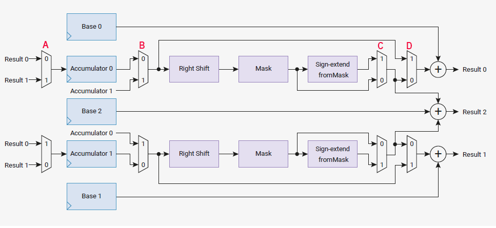
Image is slightly modified from the RP2040 hardware manual.
The configuration for FM using DDS is:
Interp0 data:
-- accum0 holds the modulation frequency DDS phase.
-- base0 holds the modulation frequency DDS increment.
-- base2 is a pointer to mod_sine_table base address.
Interp0 (FM modulation frequency) is setup to:
--
add accum0 + base0 and store result in accum0 (result0 to accum0) (add raw -- no shift)
This data path implements the Fmod DDS phase increment.
--
right-shift accum0 23 bits and mask to bits 8:1 (zero low bit for short pointer)
This implements the DDS determination of the sine table index
--
add shifted/masked accum0 to base2 and
This implements the DDS sine table address a the index determined above
-- The C progam will
read result2 as sine table address and copy (shifted) table value
plus the Fout increment
to interp1_base0.
The shift operation imlements the fm_depth multiply in the above equation.
Interp1 data:
-- accum0 holds the main frequency DDS phase
-- base0 holds the main frequency (Fout) DDS increment (sum of Fout increment and Fmod inc)
-- base2 is a pointer to sine_table base address
Interp1 (main oscillator) setup to:
--
add accum0 + base0 amd store in accum0 (result0 to accum0) (add raw -- no shift)
--
right-shift accum0 23 bits and mask to bits 8:1 (zero low bit for short pointer)/
--
add shifted/masked accum0 to base2 and
-- The C progam will
read result2 as table position output and copy table value to PWM
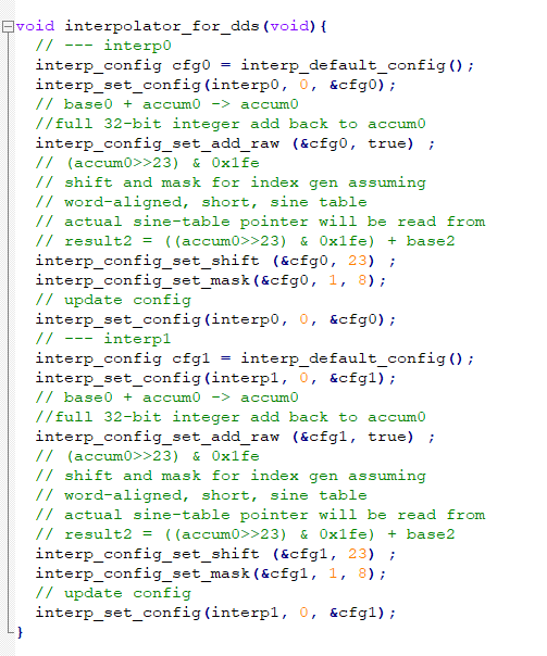
The actual setup code for interpolators is short, but obscure.
Refer often to the register diagram above and to the C_SDK sections 4.1.11 and 4.1.12.
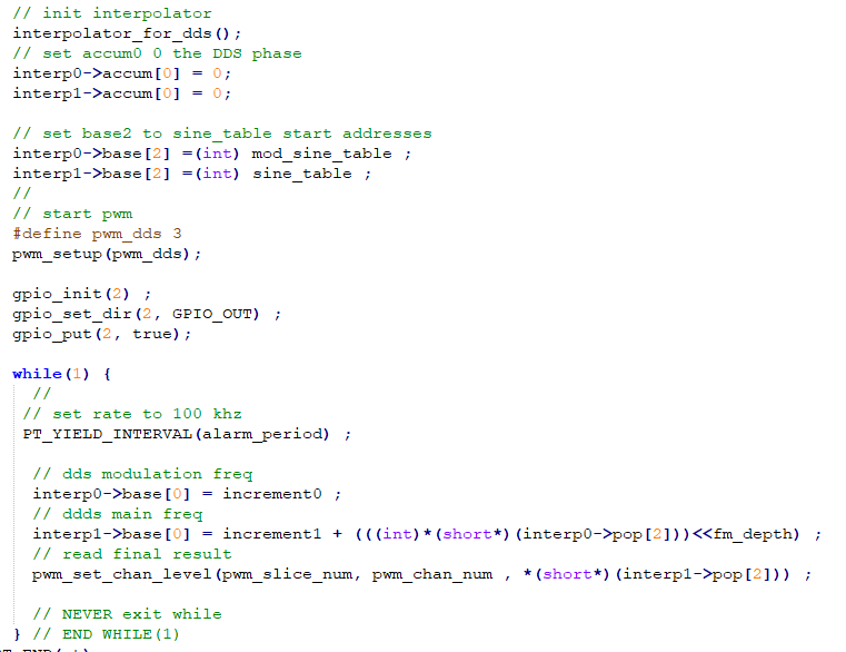
The thread which sequences the interpolators runs at Fs rate. The obscure aspects of this code are that reading any pop register on the interpolators clocks the next result in. For instance, reading interp0->pop[2] reads out the contents of the result2 register and clocks interp0. Also, the integer read from the register needs to be cast to a pointer-to-short, then accessed, then cast to int.
C_code, ZIP of project
Adding a simple amplitude envelope using an interpolator
Most sounds are recognized both by their spectral content and by their time course. The FM generator described above was modified to use another interp lane to produce a simple decaying amplitude envelope. The envelope is set to some maximum value by the C code by initializing an accumulaor. A constant in a base register is subtracted on each synthesis sample until the envelope amplitude is zero.
The basic waveform equation for this process is:
output wave = (amp_envelope(t)) * sin(Fout*t + fm_depth*(sin(Fmod*t)))
The setup code configures three lanes.
Interpolator0-lane1 (FM modulation frequency) setup to:
--
add accum1 + base1 amd store in accum0 (result1 to accum1) (add raw -- no shift)
--
right-shift accum1 23 bits and mask to bits 8:1 (zero low bit for short pointer)
--
add shifted/masked accum0 to base2 and read result2 as table position output to interp1
Interpolator0-lane0 (AM modulation amplitude) setup to:
--
add accum0 + base0 amd store in accum0 (result0 to accum0) (add raw -- no shift)
but note that base0 contains a negative number.
-- the shift/mask options were set to always output zero, so that the lane1 calculations are not affected.
Interpolator1-lane1 (main oscillator) setup to:
--
add accum1 + base1 amd store in accum0 (result1 to accum1) (add raw -- no shift)
--
right-shift accum1 23 bits and mask to bits 8:1 (zero low bit for short pointer)
--
add shifted/masked accum0 to base2 and read result2 as table position output to PWM
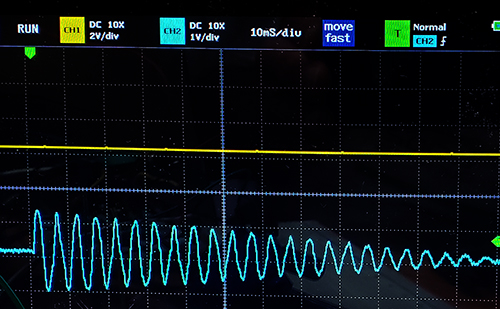
For a main frequency of 200 Hz, modulation frequency of 330 Hz,
fm_depth of 16 and decay rate of 100 we get the following waveform.
You can see the linear decay and the odd distortion due to the FM modulation.
C code, ZIP of project
It would be possible to add one more amplitude modulation (perhaps rise time)
using the interpolators, but the C overhead makes it less desirable. A more general system
is described below with the DDS units in the interpolators and amplitude envelope in C.
FM synthesizer with attack, sustain, decay envelope controls
The interpolators are used for the FM DDS, but the amplitude is set similarly to the scheme used on the PIC32. While the interpolators are using integer counter arithmetic, most of the envelope calculations will be done in s15x16 fixed point. Also, the relatively coarse fm_depth setting of the pervious examples, using shifts, will be replaced with actual fixed-point multiplies.
Copyright Cornell University
July 24, 2024