GND ---> PICO GND
+5 ----> PICO +3.3 Vdd (NOT to 5 volts!)
Rx ----> ADC channel 0 - GPIO 26
Ry ----> ADC channel 0 - GPIO 27
SW ----> GPIO 4 (with pullup turned on in software)
Cornell University ECE4760
Joystick and Encoder wheel
with 640x480 VGA 16-color
Pi Pico RP2040
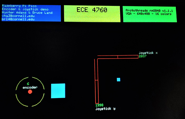
A simple joystick and encoder application for testing.
This example connects both joystick and encoder, but is stripped down to minumum graphics mostly to show how to hook up and read the devices. In the image below the Adafruit ANO rotary encoder is shown as a circle with four breaks in the circle. Each break represents a spot for a red dot representing a button push. In the image, the center button is depressed. The encoder wheel count is shown inside the circle. Pressing the center button draws two squares. One square is just to the right of the encoder icon, with a color determined by the encoder count. At the top of this page you can see the color mapping. The other square is smaller and has a location set by the joystick x,y positions. The joystick positions are indicated in the red dial-like structures. Pushing the joystick button draws a small square at the upper-left corner of the x,y indicators. One immidiately obvious 'feature' is that the noise on the analog x and y mesurements is on the order of 4 LSB. Probably better wire routing and/or some lowpass filtering would help.
Joystick connections are:
GND ---> PICO GND
+5 ----> PICO +3.3 Vdd (NOT to 5 volts!)
Rx ----> ADC channel 0 - GPIO 26
Ry ----> ADC channel 0 - GPIO 27
SW ----> GPIO 4 (with pullup turned on in software)
Encoder Connections are to the switches and grounds are:
ENCA - This is the rotary encoder A pin. ---> gpio 11
ENCB - This is the rotary encoder B pin. ---> gpio 10
COMA - Common pin A. connect to ground
SW1 - This pin is the center button. ---> gpio 9
SW2 - This pin is the down button. ---> gpio 8
SW3 - This pin is the right button. ---> gpio 7
SW4 - This pin is the up button. ---> gpio 6
SW5 - This pin is the left button. ---> gpio 5
COMB - Common pin B. connect to ground
VGA connections are shown below.
Joystick with VGA
A VGA display begs for a GUI pointer/controller.
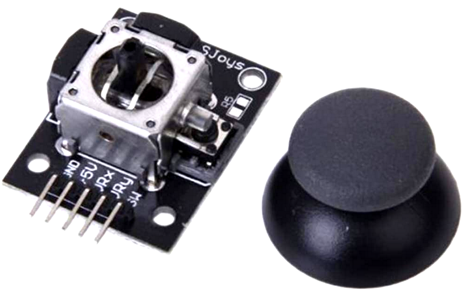
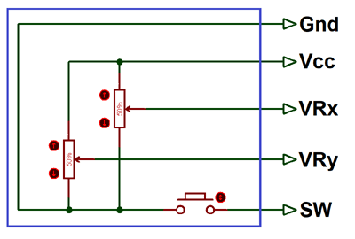
We interfaced a cheap joystick to enable a very simple interactive draw function and a basic menu. The joystick consists of two potentiometers and a push-click button. The joystick position is interpreted as a motion rate in this implementation. The connections are as shown below. The left column are the pin designations on the joystick (HiLetgo Game Joystick Sensor Game Controller Sensor schematic). To the right are the connections to the Pico.
GND ---> PICO GND
+5 ----> PICO +3
Rx ----> ADC channel 0 - GPIO 26
Ry ----> ADC channel 0 - GPIO 27
SW ----> GPIO 4 (with pullup turned on in software)
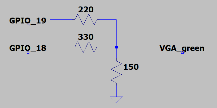
VGA video connections are as shown belowe. The default serial port (gpio0 and gpio1) are connected to a serial terminal emulator for debugging. The test program will run with no serial attached. The blue and red VGA lines are driven directly through 330 ohm resistors, as in Hunter's implementation:
- GPIO 16 ---> VGA Hsync
- GPIO 17 ---> VGA Vsync
- GPIO 18 ---> VGA Green lo-bit -- see below
- GPIO 19 ---> VGA Green hi_bit -- see below
- GPIO 20 ---> 330 ohm resistor ---> VGA-Blue
- GPIO 21 ---> 330 ohm resistor ---> VGA-Red
- RP2040 GND ---> VGA-GND
The VGA-green connection is as shown.
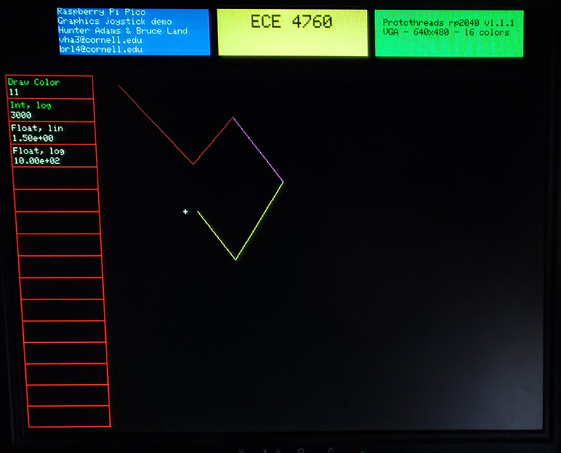
In the draw-region, clicking connects the current cursor position to the last position, to make a set of lines. In the menu-region, clicking in the box of a menu item enables edit of its value by changing the x-potentiometer. When a menu item is selected for modification by clicking in its box, a small dot appears in the item box. The change can either be in constant increment/decrement, or in constant ratios. The menu item structure supports integer and float values, specifies min and max values, increment value, increment type (linear or log), and the color of the menu item title. In the image below, the cursor is a small white cross. Each menu item is surrounded by a red box. only four of the 16 menu item slots are defined in this example: integer value, linear increment; integer value, ratio increment; float value, linear increment; float value, ratio increment. The first item controls the drawing color, according to the color table at the top of the page.
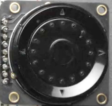
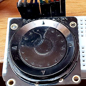
ANO Directional Navigation and Scroll Wheel Rotary Encoder
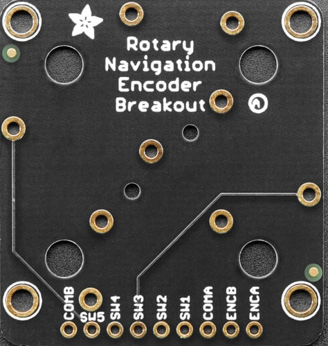
This Adafruit controller has five push buttons and an rotary encoder wheel. As shown below, when the device is oriented with the connector at the top, the five buttons map nicely into up, down, left, right, and center-select. The rotary encoder is a ring of small bumps between the center button and the four outer buttons. It is slightly difficult to press on the encoder without pressing one of the buttons (at least with my blunt fingers). The device just looks like seven contact closures which need to be pulled up by the input ports. Oriented so connnnector is at top, from right to left the switches and grounds are:
ENCA - This is the rotary encoder A pin. ---> gpio 11
ENCB - This is the rotary encoder B pin. ---> gpio 10
COMA - Common pin A. connect to ground
SW1 - This pin is the center button. ---> gpio 9
SW2 - This pin is the down button. ---> gpio 8
SW3 - This pin is the right button. ---> gpio 7
SW4 - This pin is the up button. ---> gpio 6
SW5 - This pin is the left button. ---> gpio 5
COMB - Common pin B. connect to ground
The demo code has exactly the same funcitonality as the joystick example above, with the four directional switches moving the cursor, the center button selecting a menu item and controlling drawing. The encoder wheel changes the value of a menu item.
Copyright Cornell University June 9, 2023