Introduction Support for the RP2040 has been officially ported to Arduino environment. The interesting part of this is that the port uses the MBED ARM programming base. The overall effect is that you can use the Arudino easy install and toolchain, but use only C, C++ constructs. The MBED system includes a preemptive multtasker RTOS, but currently no support for multicore, PIO, SIO, or DMA subsystems. Also, some of the device interfaces (e.g. ADC) are limited compared to what the hardware can do. The RTOS defaults to round-robin scheduling, with a time slice of about 5 mSec, and with priority control of threads. A higher priority thread always runs, if it is ready.
Setup and preliminary tests
The setup is quite easy. I liked the description at Tom's Hardware. I am using the 2.0 beta IDE. Downloading the board support package using the board manager worked well, as long as you have a fast connection. MBED documentation and examples are a little scattered, but there is a lot of material. The Pico board is not recognized completely as a program target, so you need to disconnect the Pico, hold down the program switch, and connect it. I am using a switchable USB hub for this. Before you compile, make sure the board-select text field shows Raspberry Pi Pico, with a red X next to it.
The first example code aims at trying to understand the speed of task context switches, interrupts, and i/o primitives. Two threads just toggle i/o pins at around 500 Hz. Another thread handles serial communication through the USBserial device. One of the toggle threads is used as a signal driver for an input pin set up as an interrupt source. The associated ISR just toggles another i/o line. MAIN binds the ISR to the interrupt, starts three threads and exits. Setting a pin high-low as fast as possible results in a 100 nSec pulse. Entering the ISR takes about 5 uSec and exiting about 4 uSec. For comparision, raw C-SDK calls take 1 uSec to enter and 4 uSec to exit. Context switching betwen threads is about 3 uSec, so probably the ISR entry includes a RTOS context switch. After programming, the board enumerates as a Pico on some COM port, but don't choose this. Just open a PuTTY window at attach to the COM port. In PuTTY setup, Terminal panel: Set Local echo and Local editing to 'FORCE ON'. The Arduino serial monitor does not seem to work. This code is written without using any Arduino primitives or functions. The MBED libraries and RTOS libraries replace the Arduino libraries.
The second example has a timer ISR, i/o pin ISR, a toggle thread, and the USBserial thread. The timers ISR toggles a pin, which acts as a driver for the i/o pin interrupt, which toggles another pin.The latency between the timer-triggered pulse and the i/o pin-tirggered pulse is about 10 uSec, with a jitter of 1 uSec. The latency corresponds to the time required to exit one ISR and enter another. The Ticker interrupt is good up to about 10 KHz, without loading the cpu too much. See below for information on faster timer ISR by using low level C-SDK rather than MBED Ticker.
MBED and C-SDK
MBED on Core0 with C-SDK on Core1
It turns out that MBED does not know that core1 exists, but core1 can be started and programmed using the C-SDK. Interrupts run at the C-SDK speed. There is no RTOS. One posssible user model is to put interactive, multitasking threads on core0, and put fast computational routines on core1. Of course, either core can start hardware coprocessors running, then step out of the way of DMA, PWM, PIO, an other hardware systems. As a first compatability check (Code), I started two ISRs and two threads on core0, much like the first example above, but with the addition of C-SDK calls to start the ADC and read it. This shows that (at least some) C_SDK functions can co-exist with MBED. Core1 starts an ISR, checks its core ID, then endlessly toggles a pin and increments a spin-lock protected counter. Again, only C-SDK routines are used on core1. MBED functions simply crash core1. The core0 MAIN enables the two ISRs, starts two threads, initializes the spin-lock, resets core1, then launches core1. The USB serial thread running on core0 verifies that core1 indeed starts, then prints a sequence number, the ADC reading, and the spin-lock protected count from core1. Communication is via global variables.
USBserial and Direct Digital Synthesis (DDS) MBED:USBserial and C-SDK:ADC on Core0 <and> C-SDK:DMA,PWM on Core1
The C-SDK one core1 was used to start two PWM channels and a PWM slice. The DMA channels were used to output a sine table to the PWM as fast as possible. PWM speed is about 0.5 MHz for 8-bit resolution, but the DMA channels can transfer up to about 60 MB/sec.
The DMA channels are throttled to a specific sample rate to set the desired sine wave frequency. Two DMA channels are necessary as explained in the DMA-to-PWM sinewave synthesis paragraph on the python page. The DMA channels are triggered by a high resolution timer built into the DMA subsystem. Setting the timer divider is a bit obscure, so there is a separate paragraph, DMA-to-PWM sinewave with settable frequency, describing the sine-frequency-to-timer-setting conversion also on the python page. Core0 is running MBED threads, one of which handles USB serial input/output using the usual C scanf and printf functions.The serial thread blocks on user input, and it blocks on the FIFO connected to core1. The FIFO sends the user input frequency to core1 where it is converted to DMA timer settings. Core1 cannot run any MBED objects. It has to use only native C-SDK functions to set up the PWM and DMA channels and to listen to the FIFO input from core0. The C-SDK is explained here (at great length). Hunter's page describing the DMA setup is excellent.
(Code)
DDS and monitor waveform with ADC
MBED & C-SDK:ADC>DMA>PWM on Core0 <and> C-SDK: DDS>DMA>PWM on Core1
The sine wave output from the previous example is feed back to an ADC channel attached to a DMA channel transfering the samples to a PWM slice at ADC rate. The ADC rate is settable up to 0.5 Msamples/sec to as low as 735 samples/sec in auto-sample mode (adc_run(1);). The following image shows the synthesized 1 KHz waveform on the top trace with a synthesis rate of 0.5 Msamples/sec.The bottom trace is the voltage from the low-passed PWM feed back from ADC channel zero, which is sampled at 10 Ksamples/sec. The DDS synthesis is set up on core1 and the ADC playback is setup on core0. Once set up, all of the real work is done in hardware external to the two cores. Core0 is just waiting for user input of frequency and ADC sample rate, while core1 is blocking waiting for a valid frequency value in the FIFO.
(Code)
The ADC setup turns on autosample, sets channel 0, and configures the ADC FiFO to autoload new conversion values into the FIFO. A DMA channel is configured to watch the FIFO load, then transfer the new value to a PWM duty cycle register. Once set up, the hardware grabs samples and outputs to the PWM with no cpu involvment.
PIO in MBED environment
Compatability and PIOasm
-- Introduction: The PIO subsystem contains eight completely separate, small i/o state machines for fast, cycle accurate, i/o protocol generation. Examples might be extra SPI channels, VGA driver, DVI driver, pulse density modulation, or stepper motor sequencer. There is a nine-instruction assembly language used to program each PIO state machine. The instructions are Turing-complete, but not meant for general computation (e.g. don't use them to add 32-bit integers). Each state machine has transmit-receive FIFOs which can read/written by the M0 cores, or by the DMA system. Each state machine can also read/write any of the GPIO pins. YOu can toggle an i/o pin as fast as 62 MHz, but you will not see such a fast signal if you are using a solderless breadboard. See also Hunter's excellent PIO example, PIO VGA driver for RP2040.
-- PIO processor (there are 8)
From the documentation:
 * Each PIO is programmable in the same sense as a processor:
 *   the four state machines independently
 * execute short, sequential programs, to manipulate GPIOs and transfer data. Unlike a general
 * purpose processor, PIO state machines are highly specialised for IO, with a focus on determinism,
 * precise timing, and close integration with fixed-function hardware. Each state machine is equipped
 * with:
 *  * Two 32-bit shift registers: either direction, any shift count
 *  * Two 32-bit scratch registers
 *  * 4x32 bit bus FIFO in each direction (TX/RX), reconfigurable as 8x32 in a single direction
 *  * Fractional clock divider (16 integer, 8 fractional bits)
 *  * Flexible GPIO mapping
 *  * DMA interface, sustained throughput up to 1 word per clock from system DMA
 *  * IRQ flag set/clear/status
-- The assembly language:
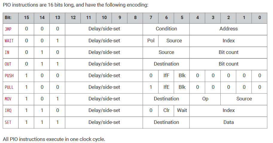
See C-SDK manual, section 3.4. Program memory is only 32 insetructions long, but each instruction can have several simultaneous effects, including a variable delay after execution (for pulse length trimming), the ability to set/clear a group of pins(side-set), and, of course, the main opcode function. Some instructions can also be set up to auto-pull or auto-push the i/o FIFOs at the same time they perform other functions. An extra SPI channel takes 5 instructions, PWM takes 7, VGA takes ~30.
-- Merging PIO code with C: PIOASM runs as a separate step in the default C-SDK make-process. The C compile details are hidden by the Arduino-MBED interface (good), but aso hides the ability to build PIO code (bad). The solution is to use a stand-alone version of PIOASM. The version I have been using is a web version at https://wokwi.com/tools/pioasm. PIOASM takes assembler source (of course) and also allows you to write some of the state machine C set up code in the same file. The output of the assembler is a C header file with an array representing the assembled PIO code, a couple of assembler-written C routines, and with the C code you specifed passed through to the header file.
-- Example 1: From examples: To test, I implemented the blink.pio example from the C-SDK example from the examples github page. There are two source files, the pio source and the C source. Pasting the pio source into the web assembler results in the header file. The main C application is just the previous dual core example, with added logic to toggle one gpio pin via the PIO. The program is large, but I wanted to test for compatability of the various libraries, and the external assembler utility. The C application can be compiled in the MBED environment, with the header file in the same directory as the C source. Remember that the C source has an ino extension becuase of the Arduino environment, but uses no Arduino constructs.
-- Example 1: Simplify the example PIO code: The example above uses 8 PIO instructions to produce a precise square wave frequency. The range of frequencies is quite large (milliHz to MHz). However 8 instructions is one-quarter of the total PIO program memory! It is possible to keep the large range and precision, while dropping the memory footprint. The original PIO assmebler code from the git site is below. The design uses two instructions to grab a value from the FIFO, then store OSR (output shift register) into Y register. The Y register is then used to reload the X register to repeatedly produce the desired delay, while setting or clearing the pin value.
.program blink
    pull block
    out y, 32
.wrap_target
    mov x, y
    set pins, 1   ; Turn LED on
lp1:
    jmp x-- lp1   ; Delay for (x + 1) cycles, x is a 32 bit number
    mov x, y
    set pins, 0   ; Turn LED off
lp2:
    jmp x-- lp2   ; Delay for the same number of cycles again
.wrap             ; Blink forever!
I found two optimizations (there may be more)
which drops the instruction count to five.
First, just leave the FIFO input in the OSR, and reload the X register from there.
Second, Use the Y register and the MOV instruction ability in invert bits to toggle an i/o bit. The resulting code performs output to the GPIO pin using the MOV insruction, rather than the SET instruction, so one line of the C program needs to be modified. The configuration mapping the SET group to an actual pin sm_config_set_set_pins(&c, pin, 1);
is modifed to
sm_config_set_out_pins(&c, pin, 1); C-code, pio-code, header-file.
.program blink
    pull block    ; wait for cpu value to FIFO, 'pull' copies to 'osr'
    ;set y, 1     ; y will be toggled for output, BUT initial state irrelevant
.wrap_target
    mov pins, y   ; Modify LED pin
    mov x, osr 	  ; reload x from 'osr'
lp1:
    jmp x-- lp1   ; Delay for (x + 1) cycles, x is a 32 bit number
    mov y, !y     ; Toggle y register
.wrap             ; Blink forever!
-- Example 1: Completely change code, but similar function:
To really minimize the PIO code, but keep the wide frequency range, it is necessary to change the C code as well as the PIO code. The PIO code is sripped down to two instructions: just a set-bit, followed by a chear-bit instruction, but each have as associated delay (0 to 31 cycles). By having the C code hack the delay values, and set the state machine clock divider we can generate frequencies as high as 62 MHz, and as low as 29 Hz. Settability is not uniform, like the previous example, but in the audio region it is quite good.
At run-time, the C program clobbers PIO instruction memory as below. The shifted 0x7 is the SET opcode (bits 13-15), the instruction delay in in bits 8-12 (five bits), and the 1/0 sets or clears the i/o pin. The delay is set to zero at frequencies above 1000 Hz, and to 31 for lower frequencies. The memory offset comes from the program load routine. pio0_hw->instr_mem[offset] = (0x7<<13) | (inst_delay<<8) | 1 ;
pio0_hw->instr_mem[offset+1] = (0x7<<13) | (inst_delay<<8) | 0 ;
The clock divider is directly set using
PIO stepper motor sequencer Unipolar (5 or 6 wire) stepper motors require a 4-phase sequence of pulses to rotate. Typically the job of producing the pulse trains is put in a interrupt-service-routine on small controllers. The PIO i/o co-processor on RP2040 can produce the sequenced pulses to offload the main cpu. The PIO unit waits for pulse-rate and sequence information from the cpu, then produces an indefinite number of pulses at that rate, until signalled by the cpu. When signalled, the PIO finishes the curent sequence of either 4 full steps, or 8 half-steps, signals the cpu that it is ready, waits for new data, then starts the new sequence.
To test this, I hooked up a 28BYJ-48 stepper motor using a ULN2003 driver and ran it (video). Half stepping these motors gives better torque and higher top speed. At 5 volts, and <0.25 amp : For single step, top pulse rate is 600/sec, but it will only pull in below 500 step/sec. For half step, you can get pull in at 1200 half-steps/sec (so 600 steps/sec) and run up to 1600 half-steps/sec (800 full). Output shaft rotates in about 2.5 seconds at full speed.
There are two source files which are compiled using the Arduino 2.0beta IDE and a PIO assembler. The C++ source file has a .ino extension The assembler I have been using is a web version at https://wokwi.com/tools/pioasm. PIOASM takes assembler source (of course) and also allows you to write some of the state machine C set up code in the same file. The output of the assembler is a C header file with an array representing the assembled PIO code, a couple of assembler-written C routines, and with the C code you specifed passed through to the header file.
There are therefore three files:
The C program uses both MBED and C-SDK functions. MBED threads are used for multitasking and USB serial support. The PIO is initialized and started using C-SDK low-level functions. The PIO itself runs a weird, stripped down assembly language, in which each opcode may execute several related functions, but ALWAYS in one cycle (including conditional jumps). There are four 32-bit registers: x, y, osr, and isr.
There are nine opcodes. Some of them used in this program:
The pull opcode grabs a 32-bit value from the CPU output FIFO and loads it into the osr register.
The mov command does what you would expect, but can optionally logically invert or bit-reverse on move.
The set opcode loads immediate data. In my program it sets i/o pin values directly.
The out opcode always operates on the osr register. It shifts out the number of bits you specify iteratively unitl it is empty or you reload osr.
The jmp opcode can perform unconditional or conditional junps in one cycle. The jump conditions are limited, but optimized for speed and i/o. Much of the function of the program depends on the context that you set up in configuration registers. For instance, the jmp opcode can be made conditional on a pin value, but only one pin, and that is specified in PIO setup C code.
PIO stepper motor sequencer + PIO cumulative step counter This version starts two PIO state machines. The first state machine is the same as the last example. The second counts edges on one of the four motor control output pins in order to give cumulative feedback on total number of steps (motor position). A PWM slice could be used to count edges, but can only count to 65535 steps. At full motor speed, this would overflow in about 40 seconds. The state machine can count to over 4 billion total steps. At full motor speed, this would overflow in about a month. Since the state machine only counts edges, actual motor position must be determined by using the cpu to appropriately add/subtract counts for forward/backward rotation. You would use this version when you want to command speed, but not absolute position.
There are the usual three files, but the pio and header files now contain the assembler code for both machines:
PIO stepper motor sequencer + PIO control step counter
Sometimes you want to have a motor run for a set distance. This version uses the counter state machine to turn off the stepper state machine after a number of pulses set by the cpu, then signals the cpu to load more move commands. As long as you do not exceed the troque limits of the motor, this version allows command of speed and position.
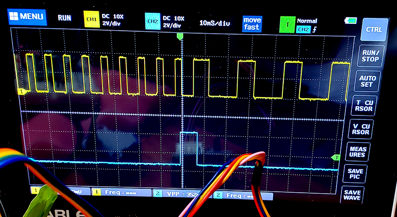
This version starts two PIO state machines. The first state machine is the same stepper as the last example. The second counts edges on one of the four motor control output pins in order to give the number of steps (motor position) for this specific motor command, then signals the stepper machine to stop. In the image below, the top trace is one phase of the 4-phase motor control and the bottom trace is the signal from the counter state machine to the stepper state machine to stop. Because the cpu had cued up a new speed, the stepper state machine immediately started a new (slower) speed. The length of the signal pulse is determined by the time to finish one full step sequence on the stepper state machine.
Using the counter, it is easy to show that one rotation of the motor output shaft is exactly 512 full steps. If the sequence parameter is set to 4-phase full-step, then exactly 2048 pulses were sent to the motor. If the sequence parameter is set to 8-phase half-step, then exactly 4096 pulses were sent to the motor. Half-step provides 1.4 times higher and more uniform torque, at the expense of twice the current. Current draw, unloaded, at 500 pulses/sec, half-step, is 0.23 amps.
There are the usual three files, but the pio and header files contain the assembler code for both machines:
The PIO programs in the source above work, but take 20 memory slots, out of a total of 32 per PIO. By using some configuration features of the state machines, I reduced to total count to 14, so that two copies driving two separate motors will fit in one PIO. This optimization required turning on autopull for the data reads, using sideset for inter-machine communication, and moving a flag-clear operation to the C program. The revised three files are
Dual (PIO stepper motor sequencer + PIO control step counter)
For a robot or plotter you need at least two motors. Using the optimized PIO programs, I fit two drivers and step counters into one PIO. You could put two more motors on the other PIO.
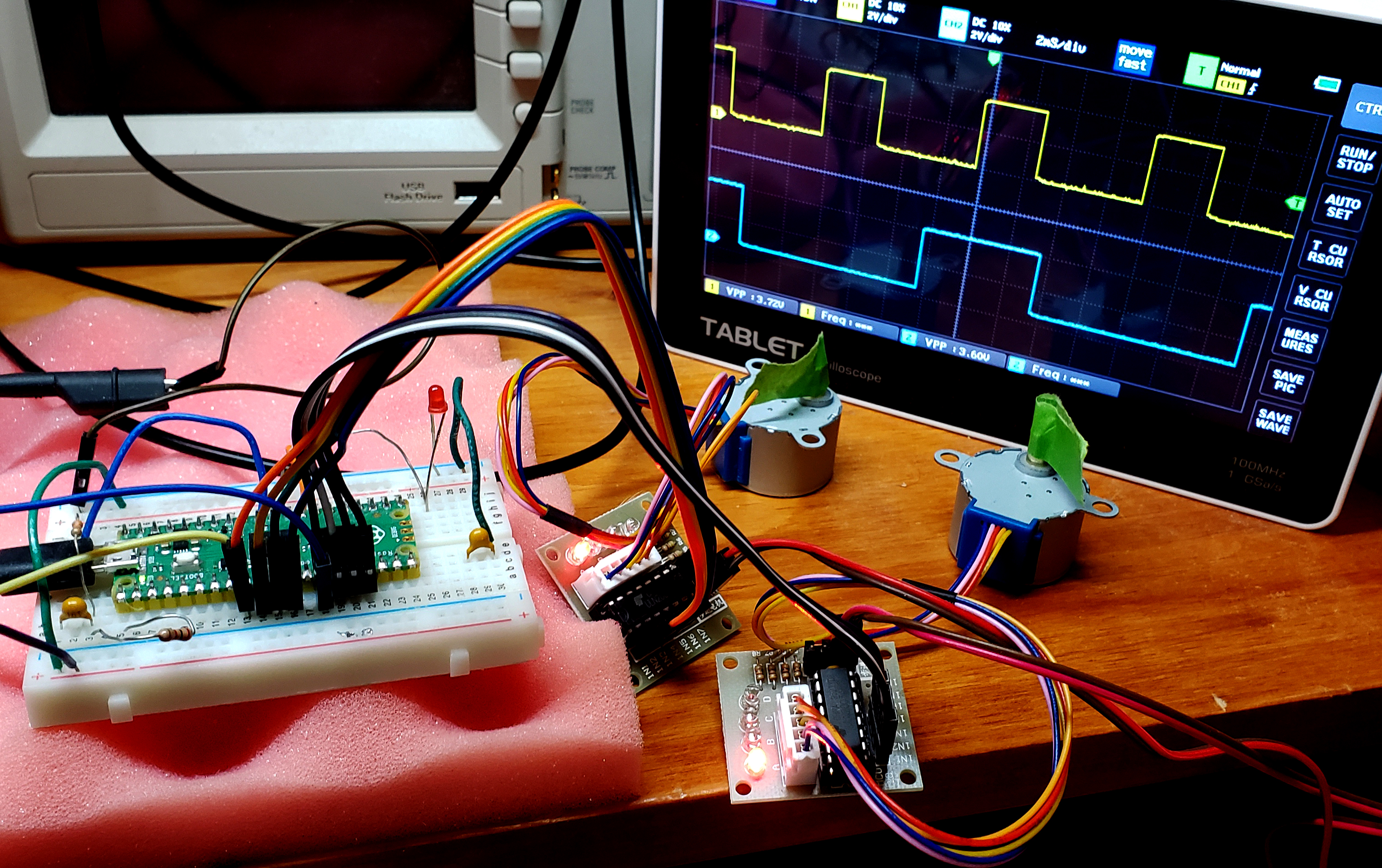
Two motors use a total of 10 pins. 4 for each motor, and one each for count-SM to stepper-SM signaling. With no load the motors draw around 0.5 amp total when running in half-step mode (better torque, more current). Using the 28BYJ-48 stepper and its ULN2003 driver board, GPIO 6 to 9 are connected to motor controller in1 to in4 on the first motor. GPIO 10 to 13 are connected to motor controller in1 to in4 on the second motor. GPIO 5 and 14 are used for signalling between state machines and should not have an external connection. The scope is showing one phase of each motor. The motor on the blue trace is running at half the speed of the motor on the yellow trace. The revised source files are a bit ponderous because of the state machine initialization routines. All that the ARM does is to start all of the state machines, ask the user for parameters, then do nothing until the sequence of steps is finished.
The full-step sequences turn on one phase at a time in one of two patterns for forward and reverse. In terms of the motor input lines the sequences are 1-2-3-4-1-2-3-4 or 4-3-2-1-4-3-2-1. These are encoded in a single 32-bit word as 0x12481248 and 0x84218421. The half-step sequences turn on one or two consecutive pins in an overlapping pattern. The sequences are 1-12-2-23-3-34-4-41 and 41-4-34-3-23-2-12-1, encoded as 0x13264c89 and 0x98c46231. Note that for full-steps four phases are completed in 4 pulse times, but for half-step four phases take 8 pulse times to complete. The 'stop' pattern, 0x80808080, just toggles the pin that the counter sate machine uses. This allows one (or both) motors to stop while still being timed by the counter state machine. The program is initialized to stop pattern. When a motor is stopped, the maximum pulse rate for pull-in is 500/sec in full-step and 1200/sec in half-step. You can go faster, but you have to use a sequence of increasing pulse rates to smoothly accelerate the motor. In half-step mode you can accelerate an unloaded motor to at least 1700 pulses/sec.
the PIO assembler source (.pio) with assembler and configuration for four machines. The stepper program is generic and can be used by both step controllers. The counter program has one hard-coded wait-on-gpio and so needed two versions.
PIO input capture of event times The RP2020 has no "input capture" peripherial that uses hardare to grab a time stamp for an external event (edge on i/o pin). Both the AVR and PIC32 that I have used can capture times in hardware, and I find it useful. The PIO can be used to implement a fast timer/counter, detect i/o pin edges, and log the time stamps at full bus rate to a 8-slot hardware FIFO. The FIFO can then be read by the M0 core at some much slower rate. The implemented capture has a useful dynamic range from 10 MHz events down to a milliHertz. If the capture rate is slower than the thread execution rate, then an indefinite number of captures is possible. If the capture rate is very high, then only the first 8 will be logged to the FIFO, then the system will stall until the CPU reads the FIFO. As configured, the PIO state machine counts at 62.5 MHz, with an overhead of two cycles per timing event (easy to compensate for). If the input is a 10 MHz square wave, there will be 6 or 7 counts recorded in each FIFO entry (barely useful). If the input is a 1 KHz square wave there will be 62500 counts per event.
PIO generated 1-bit, 255x200 resolution, NTSC video
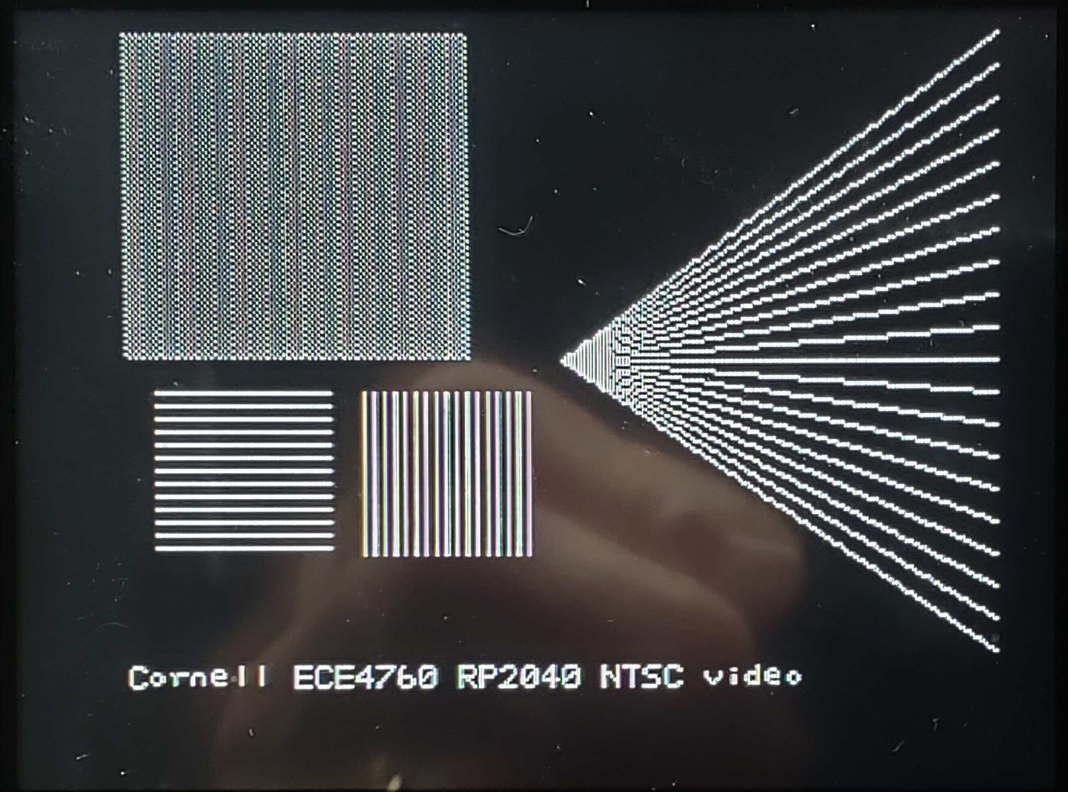
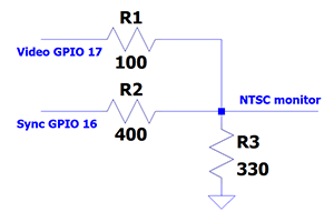
You might think that NTSC video (analog broadcast video standard in USA) is completely obsolete but it is not. The TV monitor which displays the image is quite stupid and must be sent sync and pixel data as a single time-varying voltage in realtime. As a result, the communication time demands can be high. On an 8-bit AVR, raster data transfer required 80% of the CPU! On a 32-bit PIC32 with DMA, the percentage dropped to 8%. Using the PIO parallel i/o processors on the rp2040, the ARM CPU time required to keep the monitor supplied with data is zero percent. CPU time is still required to generate the graphics content (e.g. points, lines, text), of course. The video system fit into two PIO state machines, with different clock rates. The slower machine generates the sync pulses, which have a minimum feature time of aound 5 uec. The faster machine generates the 1-bit video, with a bit time of around 0.2 uSec. The rate gives a pixel density of 256 points across the scan-line active time of 51 uSec. The rest of the 63.55 uSec scan line is used for sync and image centering.The sync and video are then combined using a two bit DAC to convert to a single voltage. Sync is defined as 0 volts, with black pixels at 0.3 volts, and white pixels at 1.3 volts. The start of each scan line is signaled by a sync pulse of just under 5 uSec. The start of a new frame is signalled by a sync pulse of about 180 uSec. One scan line is shown on the scope image.
The image below is a test image photographed from a 5 inch NTSC monitor.
The 100x100 square in the upper left is a grid with every other pixel on.
While limited, this code is sufficient base for a very cheap, audio-rate, oscilloscope.
PIO generated 2-bit grey scale, 255x200 resolution, NTSC video
A minor modification to the above code allows for 4-level gray scale drawing. The PIOs now handle 2-bit data and two data i/o lines, plus the sync output. The DAC from the previous verion was modified so that the sync-input is 470 ohms, the low order data bit is 470 ohms, and the high order data bit is 330 ohms. The output ground resistor remains at 330 ohms.
The images below show the grey scale test image and one scan line in which you can see the
video levels coresponding to the rectangles in the upper-left corner of the image screen. The scan line image
also shows two h-sync pulses and a series of very short white-level pulses corresponding to the intersection
if the scan line with the sloping lines to the right.
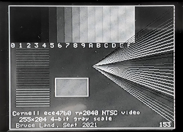
PIO generated 4-bit grey scale, 255x200 resolution, NTSC video
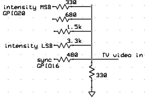
A better DAC and modification to the above code allows for 16-level gray scale drawing. The PIOs now handle 4-bit data on four data i/o lines, plus the sync output. The DAC was modified so that the sync-input is 470 ohms, the low order data bit is 3.3 Kohms, then 1.5k, then 680 ohms and the high order data bit is 330 ohms. The output ground resistor remains at 330 ohms. The drawing software was imporved to allow drawing and filling rectangles, and setting the background color of text.
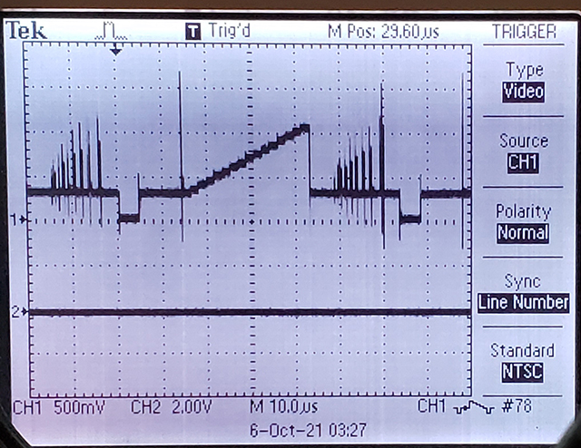
The images below show the grey scale test image with the 4-bit gray levels indicated below 16 rectangles. One scan line is shown in the other image in which you can see the voltage video levels coresponding to the grey scale in rectangles in the upper-left corner of the image screen. The scan line image also shows two h-sync pulses and a series of very short pulses corresponding to the intersection if the scan line with the different intensity sloping lines to the right.
PIO generated NTSC video animation, 4-bit grey scale, 255x200 resolution, 30 fps The PIO code was modified to send a signal to the ARM when the active pixel drawing is complete for one frame (video). This allows double-buffering of the drawing to minimize flicker during animation. Ater the active pixels are transfered to the screen there is around 2.4 mSec until the next pixel transfer starts. A DMA copy of the render buffer to the transfer buffer takes less than 100 uSec. The graphics writing performance is about 30,000 pixels/frame at 30 frames/sec. When writing rectangles, the fill rate is about 2 million pixels/sec.
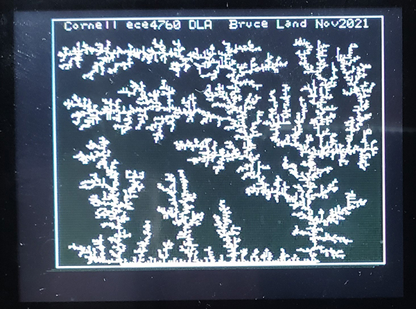
NTSC video animation of Diffusion-limited Aggregation (DLA) DLA is one way of generating fractal geometries. This example generates a 2D DLA by simulating diffusion of several thousand particles which can stick to a seed structure, but not to each other. An example is shown below, growing from a small seed at the center-bottom of the screen. They system is fast enough to animate up to 11000 particles per M0 core at 30 frames/sec. The code is parallized across the two cores by updating the first and second halfs of the particle arrays on the two cores. The graphics double-buffer, plus the particle data structures use about 80% of RAM. All bulk data motion is via DMA between buffers and to the PIO state machines.
The video shows aggregation from 22000 particles, running on both cores. The density
is high enough that there is run-away clustering.
Fixed point for C++
Floating point is relatively slow on the M0, even though there are hand-tuned floating routines in the boot-rom. For limited dynamic range realtime signals, like the ADC, fixed point arithmetic carries enough precision and is much faster. I wote three macro-based systems of fixed point, all signed: Q7.8, Q1.14, and Q16.16. The notation is <Q><number of integer bits> <binary point> <number of fractional bits>.
The sign bit is in all cases the most significant bit, and the notation is always 2's complement. I also tested the fixed point library written for C++ by Pharap. This library implements a fixed point class and features operator overloading, so that fixed point is just another data type. The class overhead is small, taking just slightly longer to execute than my simple macro expansions, but is much easier to use. I imported Pharap's library using the Arduino library manager. I tested his SQ15x16 and SQ1x14, very similar to two of my types. The C++ source just defines a bunch of fixed types, then estimates the time through a loop for each type and each operation.
Multiply:
*
Using Q15.16 or SQ15x16 is about 2x faster than floats
* Using Q1.14, Q7.8 or SQ1x14 is about 10x faster than floats
* Absolute time for float multiply is about 1 USec.
Add:
* All of the fixed pt formats are about 7-8x faster than a floating Add
* Absolute time for float add (at 125 MHz clock) is about 1 uSec
For most ADC data I use SQ1x14, with more that enough range for ADC results, including most digital filters and FFT (see below). For digital sound synthesis, or for very narrow-band fliters, SQ15x16 is probably better.
FFT
The Fast Fourier Transform I ported over from PIC32 code. The code implements a raised-cosine window, radix-2 FFT, then estimates the power spectrum using the Alpha max plus beta min algorithm (to avoid multiplies and square-root). The code just prints out the first 20 frequency bins for testing. The Q1.14 or SQ1x14 code does a 256 point window-FFT-mag calculation in ~0.9 milliSec. The SQ15x16 code takes ~3.5 milliSec.
For calculating the cepstrum (useful for speech analysis) you need to take the log of the magnitude. The floating log funciton is fairly slow, so I adapted the fixed point algorithm from Generation of Products and Quotients Using Approximate Binary Logarithms for Digital Filtering Applications, IEEE Transactions on Computers 1970 vol.19 Issue No.02. The algorithm reduces the log function range by noting that any number can be written as N=2c *(1+x) with 0≤x≤1. So log2(N)=c+log2(1+x). All we need is a short interpolation from x=0 to x =1. Using a two-segment, piecewise linear, interpolation is accurate to better than 0.02 log unit. The code uses SQ15x16 format and returns a log2 in the range of 14 to -14. The value -15 indicates underflow or attempt to take the log of a negative number. Of course, the log function is not defined for (input)≤(zero), but a real time system has to just ignore undefined inputs and return something reasonable.
C++ source for SQ15x16, 256 point, computing: data window, FFT, magnitude, and log2(mag)
Simplifing FFT specra to identify spoken vowels Vowel sounds are produced by filtering the vocal cord output (sawtooth wave) through the throat, tongue, lip resonant vocal tract. The system can be represented mathematically as the convolution of the vocal tract impulse response with the vocal cord excitation. To identify vowels, which depend on the shape of the vocal tract, we need to deconvolve the source/filter to isolate the filtering effect of the vocal tract. Taking the FFT of a convolution converts the convolution to a product of functions. Taking the log of the magnitude of the product terms converts the product to a sum. Taking the inverse FFT of the sum produces a signal which often separates the filter and excitation terms by the distance along the very weird (fake) time axis. Chopping out the longer fake times isolates the filter effect at lower fake time. Taking the FFT of this new, short time signal produces an estimate of the spectrum of the filter.The overall effect is to follow the large-scale shape of the original spectrum, while deleting the details. The order of operations is thus:
Preemphasis -- turns up the higher frequencies relative to low frequencies
Typically
data(i) = (data(i) - 0.95 * data(i-1))
Window -- the usual cos window before FFT window[ii] = (1.0 * (1.0 - cos(6.283 * ((float) ii) / (N_WAVE - 1)))
FFT -> magnitude -> log2 -- compute the usual log power spectrum
FFT -- Convert to cepstrum: compute periodicity of the log power spectrum
Truncate -- eliminate the fast spectral changes in the cepstrum (vocal cord excitation)
FFT -- convert back to power spectrum
Display 1/(magnitude) -- displays smooth peaks in original spectrum
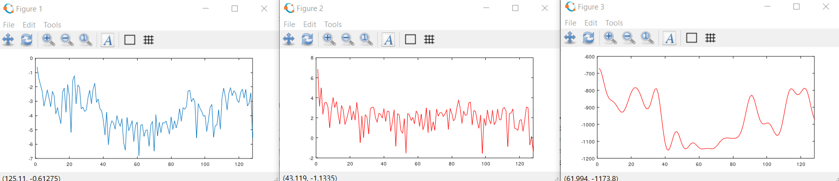
Testing was done first in Octave to understand the algorithm. The program performs the steps outlined to produce the image below. Analysis is based on 256 samples at 8000 samples/sec for me saying 'AHH'. The left image is the log-power-spectrum. Second image is the cepstrum. Third image is the smoothed spectrum. Cepstrum was truncated after the first 30 values to produce the smoothed spectrum. The first two or three peaks in the third image estimate the formants of the vowel. Since the time window for the recording is about 31 mSec, the fundamental of my vocal cords is quite near the left end of the power spectrum.
The C code to implement the algorithm can process a 256 point sample in around 15 mSec using fixed point arithmetic. This code just prints lists of data for testing. The test signal is six pure sine waves divided into two frequency groups to produce two wide 'bumps' in the spectrum. The smoothed spectrum recovered the 'bumps', so it is probably working.
C++ source to compute cepstral estimate of smoothed spectrum, but only tests the computation, and outputs as a simple text stream with no graphics.
The next step is to get ADC input of real speech, display it as a spectrogram, display the simplified spectrum versus time, and extract the formant peak frequencies. This is a ponderous amount of code because it includes the NTSC graphics drivers, FFT algorithms, and ADC initializiation. Getting this all running means setting up DMA channels for the ADC recording and video output, setting up two PIO state machines for video output, and, of course, actually doing the data acqusition and calculations as fast as possible. The basic analysis window was set to 32 mSec, with 256 ADC samples, sampling is at 8 KHz (common for speech processing). See note below on antiliasing the analog input. Computing the spectral parameters (steps 1 to 6 above) and displaying them takes about 11.5 mSec, so the system runs completely real-time.
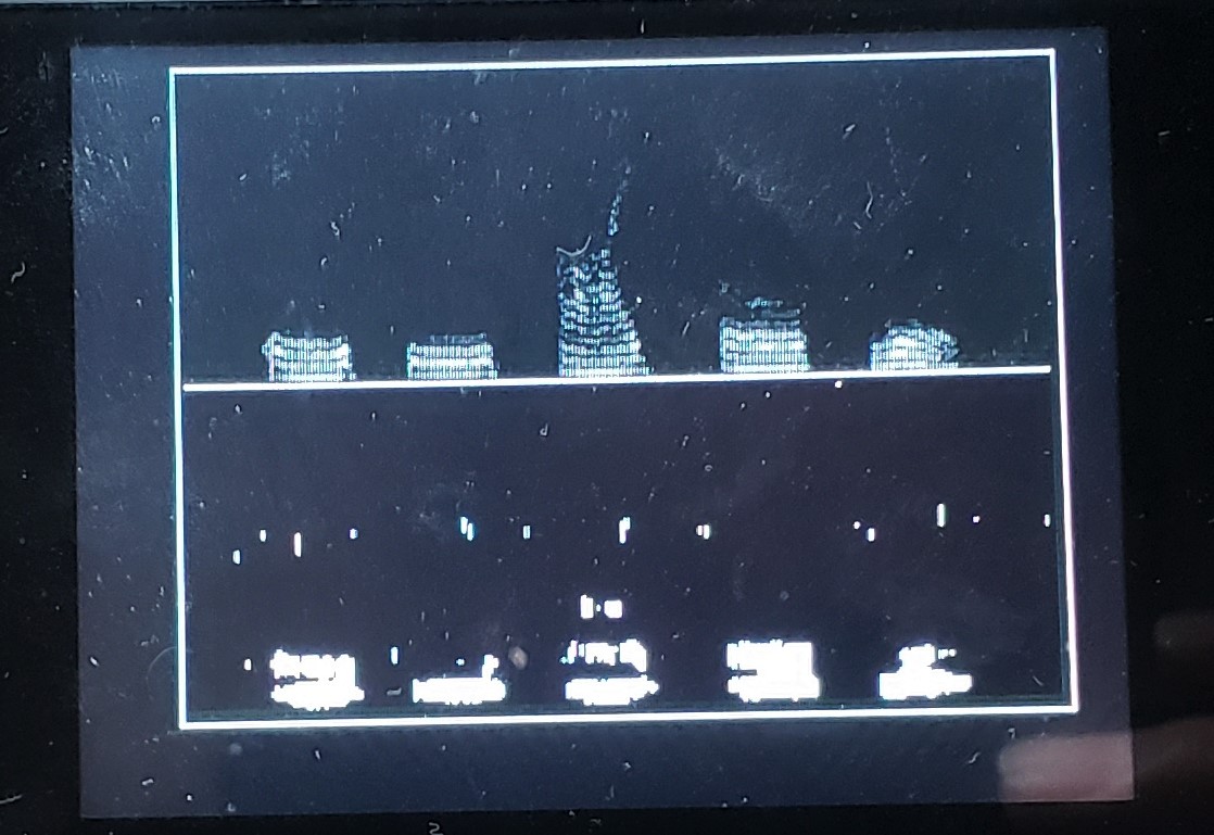
Two output images show the vowels a, e, i, o u on the left and the numerals 1 to 6 on the right
At the top is the spectrogram scaled from 0 to 3KHz vertically and running 7.8 seconds.
On the bottom
are the smoothed spectra from cepstral lowpass filtering. Peaks in the smoothed spectra were used to
estimate formants. The formant frequencies at 1 second intervals are printed near the top of the lower
panel. Formant estimates are still fairly noisy and need some averaging.
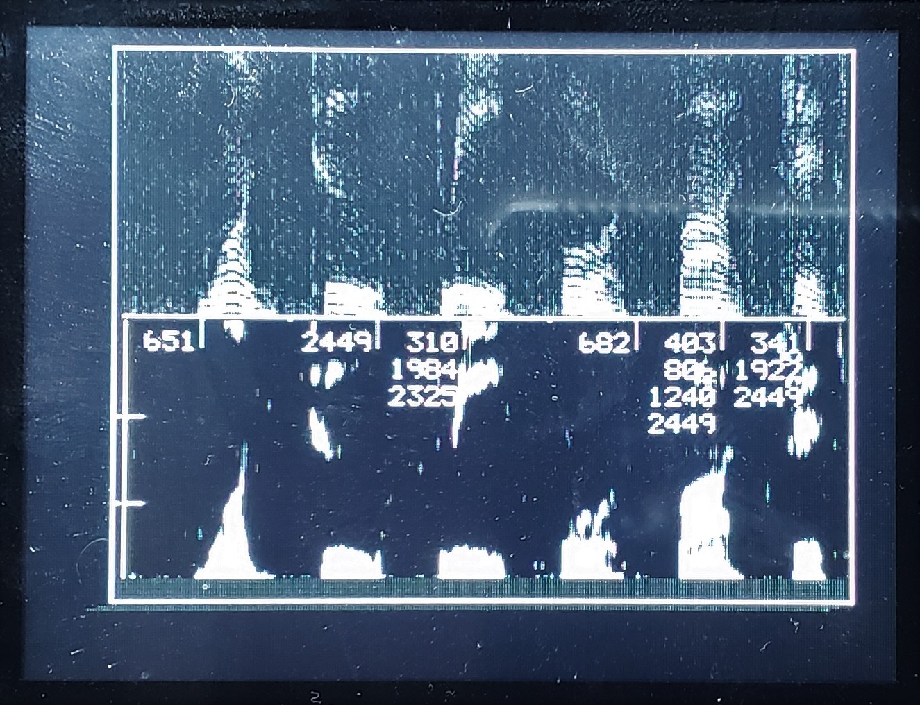
Another example is the spoken sentence: "The spirit is willing, but the flesh is weak."
I know, slightly odd, but it has a good range of sounds.
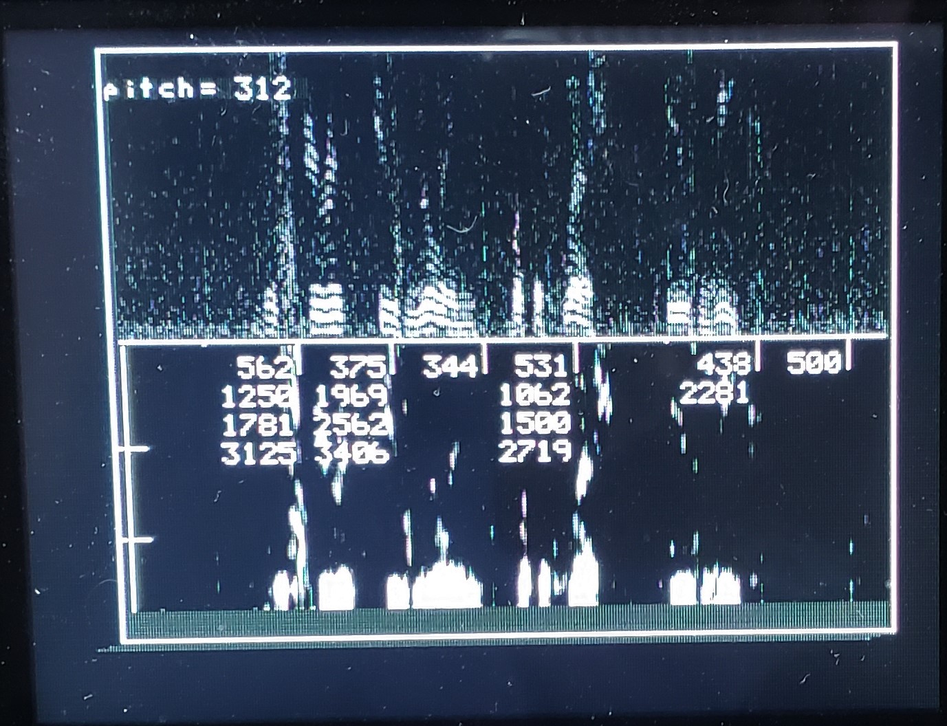
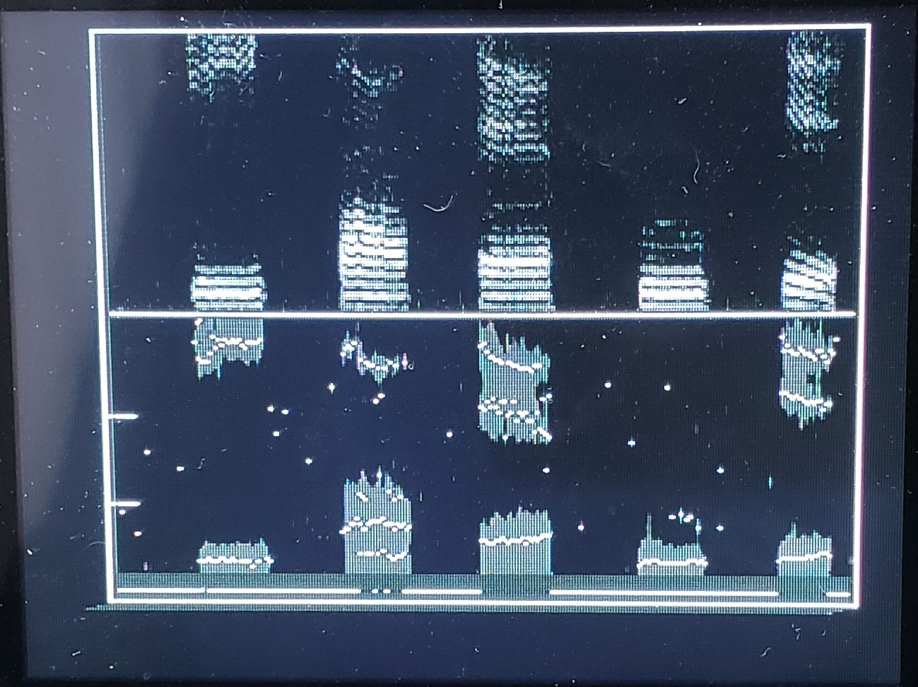
Improving the formant display. The formants change quickly, so plotting them as dots over the simplified spectra makes more sense. In the following code, the peak detection algorithm is improved to reject noise better, and the simplified spectrum is dimmed. The formants are clearly centered on the spectra maximums, as they should be.
The image shows just the vowels spoken from the words: beat - bot - bat - boot - bit
Antialiasing the ADC input
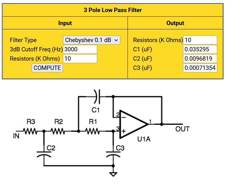
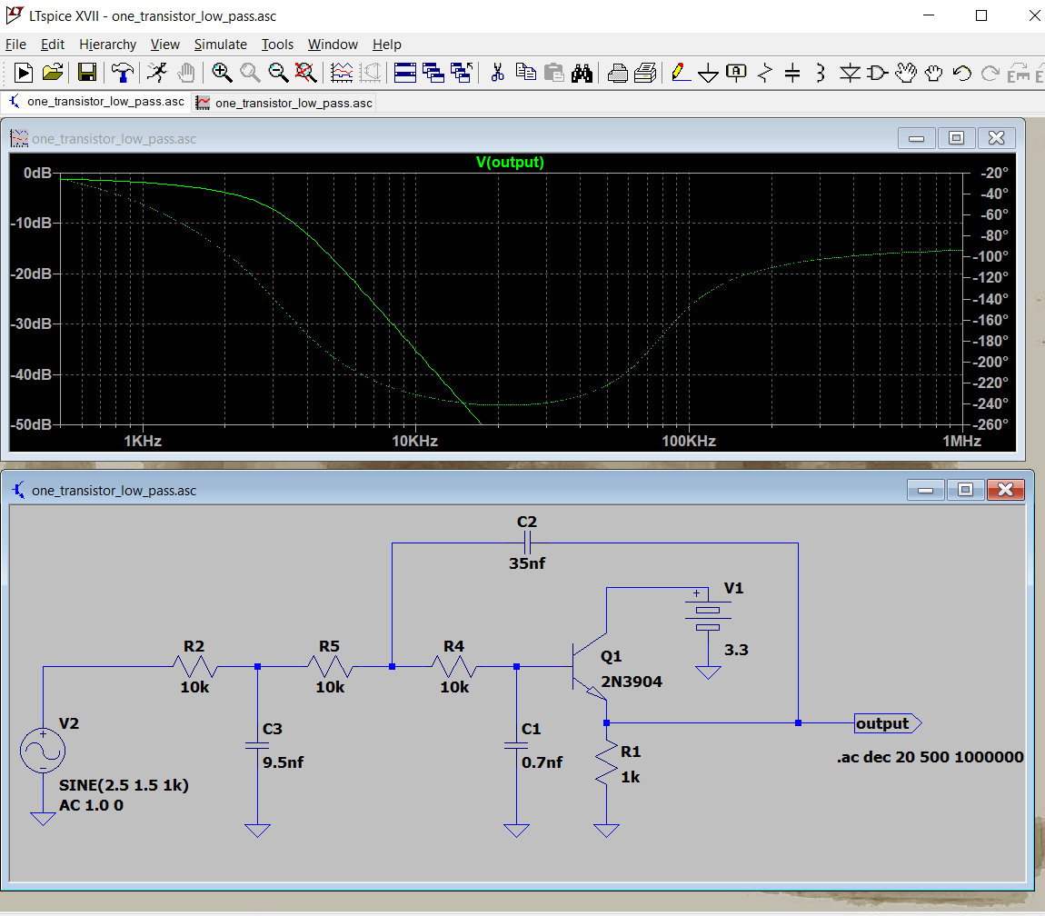
All sample data systems need bandwidth limitiation on their input to avoid aliasing. A simple RC filter will sometimes work, but a higher order active filter is often necessary. It is possible to build a 3rd order Butterworth or Chebychev filter with one opamp, or even one transistor! There are many possible designs but a 3-pole active filter design utility by Stellar Coding is easy to us to build a opamp version. Note that in the circuit diagram below (from the web page) the opamp is configured as a unity gain follower. That means that we could use a single BJT as an emitter follower, if the input and output offsets worked out right. A commercial microphone module, such as Electret Microphone Amplifier have an ouput offset of Vdd/2. If powered by 5 volts then the output offset in 2.5 volts, with an active range of +/-1 volt from 2.5 volts. Using this to feed the BJT circuit (ltspice .asc) below subtracts one silicon diode drop, 0.7 volts, from the 2.5 to make 1.8 volt offset, just about perfect for the PICO ADC. Either filter rolloff is 60 db/decade. If you power the microphone from 3.3 volts, then just use the opamp circuit.
Another approach to antialiasing is to use a clock-tunable analog filter. Such devices are made by Analog Devices and Maxim Semiconductor. They are sample-data device, but the sample rate is so high that they do not alias in the range of their own cutoff frequency. Restricting the Analog device search to 8-pin PDIP only gives 4 choices: an 8-pole elliptic filter with a very sharp cutoff, a linear-phase 5-pole bessel, and two 5-pole Butterworth filters.
Interrupt speed for GPIO, ADC, Timer ISRs(with NO MBED)
In this example, MBED was completely omitted to see how fast the C-SDK interrupts can be with no interference from the MBED scheduler. Main was configured to toggle GPIO1 pin at a few MHz. Three interrupts were configured, but only one can be used at a time because the ISRs all toggle GPIO2 pin for timing analysis.
GPIO0 pin is used as an interrupt input.The GPIO interrupt used the high level routines in the C-SDK. The timer and ADC interrupts were coded using low-level register manipulation. The high-level GPIO routines produce an ISR that takes 800 nSec to enter, and almost 4 uSec to exit. The low-level timer alarm interrupt takes ~160 nSec to get in, ~150 nSec for minimum ISR, and ~160 nSec to get out again. BUT DO NOT use Alarm 0! Something else is using it. ADC ISR speeds are similar to the timer. Code
Interrupt speed for GPIO, and Timer ISRs (MBED on core0)
Both cores are started with main in core1 just toggling an i/o pin and incrementing a timer.Core0 is running two MBED threads to blink and LED and handle serial communication. A low level timer alarm interrupt can be started either core. Both cores will run the timer ISR up to at least 500 KHz. Jitter on core1 is about 0.25 uSec, while jitter on core0 is about 3 uSec. Core0 has to take scheduler interupts from MBED. Core1 jitter probably occurs beause of memory contention with core0. But the main conclusion is that timer interrupts on either core can run interrupts at audio rate (~22 uSec interval) with plenty of time to execute fast filters, or FFT, or motor control. Code
Fixed-point lowpass filter running in ADC ISR(with NO MBED)
This example uses SQ1x14 fixed point to make a one-pole, low-pass, IIR, Butterworth filter running in the ADC ISR. Total time in the ISR is ~900 nSec, of which approximately 300 nSec is the actual filter. Filtering is good down to a bandwidth of around 0.01 of the Nyquist frequency. Two PWM channels are used to monitor ADC input and the filtered output. GPIO3 PWM outputs the ADC input. GPIO2 PWM is the filter output. GPIO1 is toggled by the ISR for timing. The ADC conversion rate is set by the ADC timer to 44 KHz. The ADC timer triggers the ADC, which when finished pushs the result (right shifted to 8-bits) onto a FIFO. Loading the FIFO triggers the ISR. Code
Fixed-point Finite Impulse Response filter in ADC ISR(with NO MBED)
The speed for SQ1x14 arithmetic seems to be around 6 MAC/microsecond, so I wrote a FIR with 31 taps to get a better idea of timing and to see if the rp2040 is fast enought to do a full Head-Related Impulse Function in real-time. It is almost fast enough with one core, assuming impulse response lengths of 64 samples, so using both cores would work. The 31 tap filter ran in ~6 uSec. I used the Octave command fir1(30, .1) to design the filter. Code


