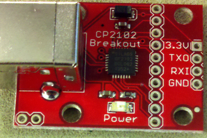
Solder a header to the board. Do not connect 3.3 volts to anything.
Connect TXO to the MCU RX pin.
Connect RXI to the MCU TX pin
Connect gnd to MCU ground.
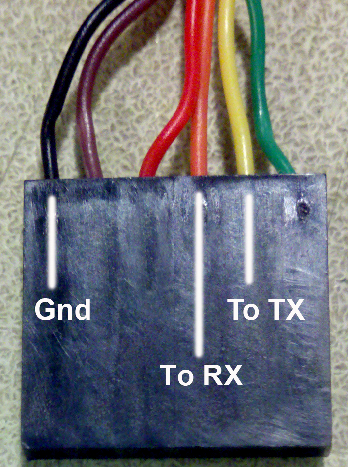
Use wires to connect the the three signals shown.
You will build a digital tachometer which displays motor speed on a LCD display
and controls the motor with user-selectable parameters to maintain constant speed. You will be required to use a multitasking kernel and write your program as tasks within the kernel API.
Procedures.
Serial Connection:
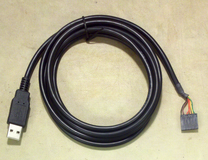
There will be a USB connection for serial communication between the running program and the PC, which will be running PuTTY. Set up PuTTY for 9600 baud, no parity, 1 stop-bit, no flow-control.
In the PuTTY config window, choose serial connection, then click serial in the left hand panel and set the parameters. Connect PuTTY to whatever serial port the USB connection configures. Use Control Panel...System...Hardware Tab...Device Manager Button...+Ports to find out which serial port is connected to the USB connection. There are two styles of USB connection:
Concurrency:
For this assignment you must write your code for a multitasking
kernel called Tiny Real Time (TRT).
Look through the examples on the TRT
page to see how to use the API and to download the kernel.
You must edit the trtSettings.h file!
If the kernel continually resets then:
main becomes the default
task. Don't put any initialization or other code in main except for the uart init.(deadline)
- (release
time) should be greater than the LCD update time so that the kernel
can meet all the deadlines. If you give a slow task a release time equal
to it's deadline, then it has to execute in zero time to meet deadline,
and nothing else can run until the slow task completes. Experiment with this
test code by changing the
difference in the spoiler task while watching A.0 on the scope.
Generally speaking, the deadline-release time difference should be greater
than the execution time of the thread between kernel sleep calls. Mount at least two LEDs and push buttons for testing, as explained in the code.int0 (pin D2). The motor_period and motor_period_ovlf variables should declared as volatile int.
// --- external interrupt ISR ------------------------
ISR (INT0_vect) {
        motor_period = TCNT2 + motor_period_ovlf  ;
        TCNT2 = 0 ;
        motor_period_ovlf = 0 ;
}
// --- set up extra 8 bits on timer 2 ----------------
ISR (TIMER2_OVF_vect) {
        motor_period_ovlf = motor_period_ovlf + 256 ;
}
You will, of course, need to turn on timer 2, set up the timer 2 overflow interrupt, and set up int0 in main.
//set up INT0
EIMSK = 1<<INT0 ; // turn on int0
EICRA = 3 ;       // rising edge
// turn on timer 2 to be read in int0 ISR
TCCR2B = 7 ; // divide by 1024
// turn on timer 2 overflow ISR for double precision time
TIMSK2 = 1 ;
IR sensor:
We will be bouncing infrared light off the hub of the fan and detecting intensity
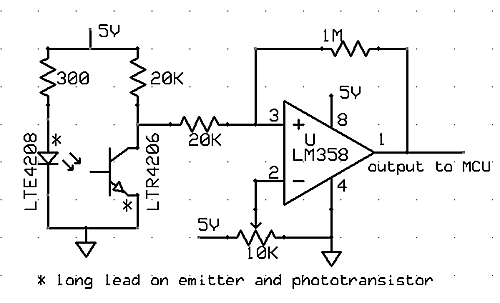
variations in the reflected light to determine the speed. The circuit below
uses a infrared emitter to shine light onto
a surface. The relected light is detected by a phototransistor.
You will want to run the phototransistor output through an opamp comparator
to produce fast, logic-level output swings. Even if the levels at the output
of the phototransistor are compatable with CMOS logic, the rise time of the
light will be too slow for accuracy. The 10K potentiometer sets the comparator
threshold, the 1M resistor sets the hysteresis and may need to be adjusted.
Hysteresis makes the rising/falling edges of the waveform less sensitive
to noise.
Note the * in the following
schematic indicating the long component lead!
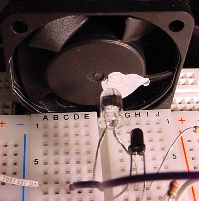
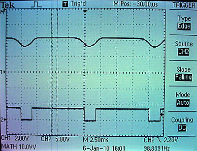
The left image below shows a fan with a dab of white paint on the hub. The clear IR emitter is pointed at the hub. The dark phototransistor is also pointed at the hub. The top trace on the right shows the output from the phototransistor. As the white paint rotates in front of the sensor, the transistor turns on and the voltage drops. The bottom trace shows the output of the opamp. The threshold should be adjusted so that the opamp switches at a voltage where abs(dv/dt) is high.
The output of the opamp could be fed directly into the int0 external
interrupt pin (MCU pin D.2), as long as the opamp power rails are +5 and ground.
Keep the opamp output away from the PWM lead coming from the MCU.
Capacitative coupling can corrupt the output of the opamp!
For debugging, you can see a slight glow in the IR emitter using your cell phone camera because a solid state camera is sensitive to infrared light. You may need to shield the phototransistor from the LED by slipping a small piece of black paper between them so that the transistor sees the white paint, but not the LED. The symptom will be that the transistor output is always low.
Motor Control:
You will need to drive a fan from the mcu. Fans have motors which can cause
nasty inductive spikes to wipe out the transistors in the mcu port. The
circuit shown below is fairly safe. An optoisolator completely isolates
the MCU from the motor. The diode placed across the motor shorts out spikes
when the motor is turned off. The resistor grounding the base of the phototransistor
should be set for best falltime, probably around 1Mohm. The motor capacitor
should start around 0.1uf. Increase it if there is too much spike noise on
the analog input, but be sure to use ceramic capacitors, not electrolytic.
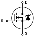
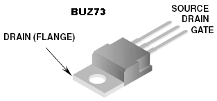
Electrolytic capacitors are too slow. The pinout of the 4N35 optoisolator
and BUZ73 or 2SK4017 are also shown. Note that the bandwidth
of the 4N35 is very small, so use a low PWM frequency, perhaps about 1000
Hz.
A matlab program demonstrating the PID control algorithm includes the following nonlinear effects: The sensor is modeled as producing a new value once/revolution. The effect is to make a feedback which is dependent on the speed of the motor, with the motor becoming more stable at higher speed. The motor is modeled as a second-order system when it is powered, and a first-order system when it is coasting. The controller has saturation (maximum voltage) and rectification (no negative output).


Assignment
Write two to four tasks using the TRT kernel API and construct a circuit which will:
s 300p 10i 2d 5.2 You will demo all the features above to your TA.
Your program should not need to be
reset during the demo.
Your written lab report should include the sections mentioned in the policy page, and :