You will use the digital oscilloscope as an analog x-y display to simulate an etch-a-sketch. The device will be controlled by a 16-key keypad. As you push directional buttons on the keypad the device will leave a trail of dots on the 'scope screen.
Procedure:
You will need to build two simple digital-to-analog converters as shown below.
One for the 'scope x input, one for the y input. On the 'scope press the Display
button, then use the on-screen menu to change the format to XY.

The Keypad:
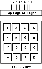
You will need to get user input from a keypad with the following configuration. Demonstration keypad scanning code is in ASM and in C.

Pin 1  -- row 1 2 3 A
Pin 2  -- row 4 5 6 B
Pin 3  -- row 7 8 9 C
Pin 4  -- row * 0 # D

Pin 5  -- col 1 4 7 *
Pin 6  -- col 2 5 8 0
Pin 7  -- col 3 6 9 #
Pin 8  -- col A B C D

(a) Each switch shorts one row to one column.
(b) Each pin should be connected to one bit of an i/o port.
(c) The i/o port pins will be used both as inputs and outputs.
    When they are inputs, they should have active pullup resistors.
Write a program and build a circuit which will:
When you demonstrate the program to a staff member, you should exercise the keypad commands to draw a picture. Full credit will be given only if you can store more points than you have bytes of RAM. Since you have 1k byte of RAM, you will need to draw at least 1000 points in 33 mSec. The code which blasts points from RAM to the DAC will probably have to be written in assembly language for adequate perfromance.
Your written lab report should include: