EE 476: Laboratory 1
Reaction Time Tester.
Introduction.
This assignment introduces you to the software and hardware development tools
you will use this semester to work with the Atmel AT90-series microcontroller
(MCU) chips. You will use the STK500 development board to build a human reaction
time tester. The STK500 pushbuttons, an external LCD, and the mcu will be used
to see how fast you can push a button after a light flashes.
Hardware
The hardware you will be using to
support the AT90-series is the Flash MCU evaluation board, a small board providing:
- A target AT90-series microcontroller (mcu) with onboard flash program memory.
- A programmer for the target flash memory, including a serial connection
to a PC.
- Eight general pushbuttons, eight LEDs and a RESET button.
- A serial connection for applications.
- Connectors for bringing out the microcontroller signals to user-designed
peripheral equipment. Note that there is no protection on these lines. You
are connecting directly to the mcu. Prudent design suggests you might want
to use buffers when you are uncertain of voltage levels or other conditions.
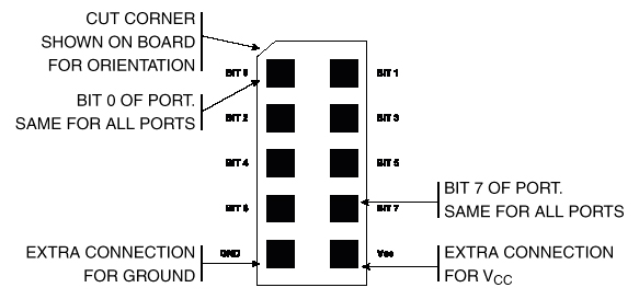
The pin definitions for the connectors are shown below. The inner squares
represent pins. The outer border is a white line surrounding the plug.
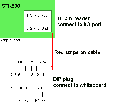
- There are cables connecting the 10-pin header plugs shown above to DIP plugs
to make it easy to connect to the usual white protoboards. The connection
pinnout is given below.
A small power supply provides power to the development board. The demo codes
given in this lab are written for the MEGA32, but many of the examples throughout
the 476 web site are written for the 8515 or MEGA163 mcus. This year we are
using the MEGA32 which has more memory. To run the 8515 or MEGA163example programs
you will need to:
- Change the header file to
<Mega32.h>
- You will need to program the clock select bits in the CodeVision setup:
choose "External crystal/slow power up"=1010
- TIMSK bit definitions are different from the 8515. You must modify any reference
to TIMSK.
- UART register names have changed.
- The programmer cable connects to the PC serial port. Do
NOT use the Altera dongle.
The Liquid Crystal Display (LCD):
A 16 character, two line (16x2), LCD display be used
as a numerical display. The display we are using has an industry-standard interface.
A more detailed data sheet for a similar
display shows the command set. There are several aspects of the display you
should note:
- Connecting the power backwards will destroy it.
Always check the polarity before connecting the display.
- The 14 pin header is on the lower-left corner of the display. Pin 1 is
closest to the left edge of the pc-board.
- Since the display only draws about 1-2 mA, you can use port VTG pin for
+5 volts. You may need a 10k or 20k trimpot to adjust display contrast connected
as shown in the following program. But first, try hooking LCD contrast control
(pin 3) to ground.
- The LCD interface to the mcu is documented in the CodevisionC libraries
and in a short C program which you can use to test
your LCD connections. Note that this program uses a software delay to time
the display, something you can never do if your program has to respond to
external events.
- The character representation is identical to ASCII codes for numbers, letters
and most symbols. Refer to the data sheet above for a complete listing.
- The LCD display is arranged as 2 lines of 16 characters and is addressable
on a per-character basis.
Software
Software you will use consists of:
Procedure:
- Make sure the evaluation board is connected to power and to the PC as specified
in the evaluation board description. Turn on the power supply with the switch
on the board. An LED in the middle of the board should cycle from red to yellow
to green. For this first lab, there should be jumpers on the PortB to the
LED header and on PortD to the switch header. Ask your instructor for help
if these are not installed.
- Make a subdirectory for your group in the
My Documents folder.
Name it with your netid.
Be sure to put all your files there and to back up daily!.
- There should be a shortcut to Codevision C on the desktop.
- After you define a new project, you can add a C source file and edit it.
- Save this code (from the Program
Organization page) into your directory. This program blinks LEDs and
responds to buttons. It is organized as three task subroutines. You will
modify this code in the assignment below.
- Under the
Project menu, choose Configure...
, then in the Files tab, add the source code to the project
you just defined.
- In the
Compiler tab, set the Chip type to
Mega32.
Also set (s)printf features to int,width.
- In the
After make tab, set
the Program the Chip checkbox.
Set CKSEL0 and CKSEL2.These select the clock
source.
You may need to uncheck the Check Signature box.
Then close the configure dialog.
- Click on the compile icon. A message window will open to tell you if
there are errors in the code. If there are errors, The open the listing
file to see where they are. If the compile is successful, you should be
able to download the program to the STK500 board and see some blinking
LEDs.
- Connect the LCD and run the LCD test program. You should see a counter and
a moving dot.
-
You will need to generate a time base for measuring reaction times. Most
people have a reaction time in the range of 100 mSec to 200 mSec, but this
can be quite variable, up to several hundred mSec.I suggest that you use
the multiple task timing scheme from this code.
- Remember that a switch which is pushed reads back a logic zero.
Assignment
Be prepared to demo the program you wrote to your TA in lab.
Your written lab report should include:
- How accurate was the interrupt time base in the program you were given?
How could you make it more accurate?
- Why did we make you use interrupts rather than wait-loops?
- The scheme you used to detect the pushbutton state. (e.g. polling loop,
interrupt)
- Other design aspects of the assignment.
- A heavily commented listing of your code.
- Your reaction times and the reaction time of your TA.
Copyright Cornell University Jan 2004