You will construct a device with produces a a series of musical notes. The note sequencing will be determined by a Markov process. Synthesis of sounds will be controlled by your choice of additive, FM, or Karplus-Strong algorithms. A keypad will be used to set Markov and synthesis parameters.
Examples from 2012:
From Ranjay Krishna: Fur Elise, Star Wars, Harry Potter
Procedure:
You will build a syhtnesizer with audio output to amplified speakers. Analog output will be in the form of a PWM signal which will go to the audio input of the speakers. The PWM signal will be low-pass filtered enough by the speakers. The PWM signal will be mixtures of sinewaves generated using Direct Digital Synthesis (DDS), then added, multiplied and/or filtered. . For this lab, you will need to produce some waveform more interesting than a pure sine wave. This example shows how you can generate an FM modulated sinewave by DDS. This example shows how to generate additive synthesis. This example generates an audio sine wave and white noise. More explanation and examples are available on the DSP page. Use the timer0 fast PWM mode with the prescalar set to 1 to produce 62500 PWM pulses/sec, but only update the PWM at 8000 samples/second. A matlab program generates FM syntheisis for testing parameters and another matlab program generates power-law probabilities, normalized to 127.
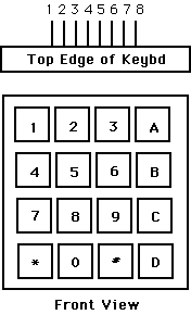
You will need to get user input from a keypad with one of two following configurations. Some keypads have the connector on the top, as shown. Some have them on the bottom. A demonstration keypad scanning code for testing your connections is here. An example of a debounce state machine for a single STK500 pushbutton (not the keypad) is included here for reference.

Connector:  top:8-pin      top:9-pin   bottom
Pin 1  ---- row 1 2 3 A    col 1       col 1
Pin 2  ---- row 4 5 6 B    col 2       col 2
Pin 3  ---- row 7 8 9 C    col 3       col 3
Pin 4  ---- row * 0 # D    col 4       col 4

Pin 5  ---- col 1 4 7 *    row 1       row 1
Pin 6  ---- col 2 5 8 0    row 2       row 2
Pin 7  ---- col 3 6 9 #    row 3       row 3
Pin 8  ---- col A B C D    row 4       row 4
Pin 9  ----              (NO CONNECT--common)

(a) Each switch shorts one row to one column.
(b) Each pin should be connected to one bit of an i/o port.
(c) The i/o port pins will be used both as inputs and outputs.
    When they are inputs, they should have active pullup resistors.
(d) On the 9-pin models, do not connect the common lead.


Hints on debugging are here.
| note names | C4 | D4 | E4 | G4 | A4 | C5 | D5 | E5 |
| frequencies (Hz) | 262 | 294 | 330 | 392 | 440 | 523 | 587 | 659 |