Cornell University
Electrical Engineering 476
Video Generation history
Introduction
This page documents the steps in developing the video software.
Video Generation
There are several very good references for understanding how TVs are controlled by a pulse sequence. I particularly liked the Stanford EE281 Handout #7 entitled "TV paint". Also very useful were Software generated video, by Rickard Gunée, Video Tutorials by Glen A. Williamson, and various excellent projects by Alberto Riccibitti.
The goal is to generate non-interlaced, black and white video,
with enough image content to be interesting as a graphics device. The software
described here implements an NTSC-rate, non-interlaced, video signal. For ease
of teaching, I wanted as much of the code as possible to be in C, with litttle
or no assembler. The first version of the code is entirely in CodeVision C and
generates a 64 (horizontal) by 100 (vertical) bit map. The CodeVision compiler
controls (in the Project:Configure... menu) must be set to default
to:
signed charThe "video engine" consists of two parts:
These parts are described in the next two paragraphs.
Sync Generation
Since uniform pulses are required every 63.5 microseconds to cause horizontal sync, the natural choice is to run timer 1 at full speed (8 MHz), and interrupt on compare match after 508 timer ticks. However, if you use 63.625 microseconds (509 timer ticks), then each frame is exactly 1/60 of a second, so building software timers is easier. If you just enter the ISR directly from running code, the time to enter can vary by a couple of machine cycles, which is several 100 nanoseconds. This variability causes unacceptable visual jitter on the TV. The solution, originally used by Alberto Riccibitti is to put the mcu to sleep just before the interrupt will occur. The version of the code shown below puts the sleep command in a while loop which is executed once per horizontal line for lines 1 to 230 (the image content). Between line 231 and line 262, the main loop executes once per frame functions, such as raster updates. During this interval, a few sleep commands are scattered through the code to keep the sync accurate. The ISR code which generates the sync is shown below. All of the logic for counting lines, inverting the horizontal sync to make vertical sync, and running the i/o port are contained within the 5 microsecond pulse time. This ISR must be entered from the mcu "sleep" state to reduce jitter.
interrupt [TIM1_COMPA] void t1_cmpA(void)
begin
  //start the Horizontal sync pulse
  PORTD = syncON;
  //count timer 0 at 1/usec
  TCNT0=0;
  //update the curent scanline number
  LineCount ++ ;
  //begin inverted synch after line 247 to make vertical sync
  //note that at least 3 lines before this must be left at BLACK
  //level for the TV to lock on properly
  if (LineCount==248)
  begin
    syncON = 0b00100000;
    syncOFF = 0;
  end
  //back to regular sync after line 250 to make the
  //required 10 blank lines before starting a new frame
  if (LineCount==251)
  begin
    syncON = 0;
    syncOFF = 0b00100000;
  end
  //start new frame after line 262
  if (LineCount==263)
  begin
     LineCount = 1;
  end
  //end sync pulse
  PORTD = syncOFF;
end
Image Generation
The displayed image is stored in an 800 byte array in the RAM of the Mega163. The image bits are packed so than 8 displayed bits are stored in each byte. This gives a resolution of 6400 total addressable points. To speed up dot generation (and produce a tighter raster) the eight array bytes for one line are preloaded into registers. Each bit can then be put on the screen in 4 machine cycles. All loops must be unrolled to keep the rate constant during one line. There are a set of variables which are declared which must be the very first variables to be declared. The compiler puts these in registers. The code depends on register allocation for speed. Note that CodeVision version 1.23.7 changes register allocations. A new version which corrects the complier dependencies is in the the Optimization and Bug Fixes section near the bottom of this page. Also near the bottom of the page is an improved Mega32 version.
char syncON, syncOFF, v1, v2, v3, v4, v5, v6, v7, v8;
int i,LineCount;
The actual image is generated by copying RAM into registers v1-v8 at the beginning of a line, then blasting them out of registers as fast as possible to make a dense raster. The following while loop waits for each sync pulse in sleep mode, then processes one line.
while(1)
  begin

    //precompute pixel index for next line
    if (LineCount<ScreenBot && LineCount>=ScreenTop)
    begin
       //left-shift 3 would mean individual lines
       // << 2 means line-double the pixels so that they are
	   //about as tall as they are wide.
	   //The 0xfff8 constant clips the lower 3 bits so that the
	   //byte address within a line can be added after the sleep.
       i=(LineCount-ScreenTop)<< 2 & 0xfff8;

   end

   //stall here until next line starts
    //sleep enable; mode=idle
    //use sleep to make entry into sync ISR uniform time

    #asm ("sleep");

    //The code here to executes once/line.
    //--Usable lines 1 to about 240, but
	// the raster is written on lines 30 to 230.
	// Any other processing must occur on lines 1-30 or 231-262.

    if (LineCount<ScreenBot && LineCount>ScreenTop)
    begin
      //load the pixels for one line into registers for speed
      v1 = screen[i];
      v2 = screen[i+1];
      v3 = screen[i+2];
      v4 = screen[i+3];
      v5 = screen[i+4];
      v6 = screen[i+5];
      v7 = screen[i+6];
      v8 = screen[i+7];

      //now blast the pixels out to the screen
        PORTD.6=v1 & 0b10000000;
        PORTD.6=v1 & 0b01000000;
        PORTD.6=v1 & 0b00100000;
        PORTD.6=v1 & 0b00010000;
        PORTD.6=v1 & 0b00001000;
        PORTD.6=v1 & 0b00000100;
        PORTD.6=v1 & 0b00000010;
        PORTD.6=v1 & 0b00000001;

        PORTD.6=v2 & 0b10000000;
        PORTD.6=v2 & 0b01000000;
        PORTD.6=v2 & 0b00100000;
        PORTD.6=v2 & 0b00010000;
        PORTD.6=v2 & 0b00001000;
        PORTD.6=v2 & 0b00000100;
        PORTD.6=v2 & 0b00000010;
        PORTD.6=v2 & 0b00000001;

        PORTD.6=v3 & 0b10000000;
        PORTD.6=v3 & 0b01000000;
        PORTD.6=v3 & 0b00100000;
        PORTD.6=v3 & 0b00010000;
        PORTD.6=v3 & 0b00001000;
        PORTD.6=v3 & 0b00000100;
        PORTD.6=v3 & 0b00000010;
        PORTD.6=v3 & 0b00000001;

        PORTD.6=v4 & 0b10000000;
        PORTD.6=v4 & 0b01000000;
        PORTD.6=v4 & 0b00100000;
        PORTD.6=v4 & 0b00010000;
        PORTD.6=v4 & 0b00001000;
        PORTD.6=v4 & 0b00000100;
        PORTD.6=v4 & 0b00000010;
        PORTD.6=v4 & 0b00000001;

        PORTD.6=v5 & 0b10000000;
        PORTD.6=v5 & 0b01000000;
        PORTD.6=v5 & 0b00100000;
        PORTD.6=v5 & 0b00010000;
        PORTD.6=v5 & 0b00001000;
        PORTD.6=v5 & 0b00000100;
        PORTD.6=v5 & 0b00000010;
        PORTD.6=v5 & 0b00000001;

        PORTD.6=v6 & 0b10000000;
        PORTD.6=v6 & 0b01000000;
        PORTD.6=v6 & 0b00100000;
        PORTD.6=v6 & 0b00010000;
        PORTD.6=v6 & 0b00001000;
        PORTD.6=v6 & 0b00000100;
        PORTD.6=v6 & 0b00000010;
        PORTD.6=v6 & 0b00000001;

        PORTD.6=v7 & 0b10000000;
        PORTD.6=v7 & 0b01000000;
        PORTD.6=v7 & 0b00100000;
        PORTD.6=v7 & 0b00010000;
        PORTD.6=v7 & 0b00001000;
        PORTD.6=v7 & 0b00000100;
        PORTD.6=v7 & 0b00000010;
        PORTD.6=v7 & 0b00000001;

        PORTD.6=v8 & 0b10000000;
        PORTD.6=v8 & 0b01000000;
        PORTD.6=v8 & 0b00100000;
        PORTD.6=v8 & 0b00010000;
        PORTD.6=v8 & 0b00001000;
        PORTD.6=v8 & 0b00000100;
        PORTD.6=v8 & 0b00000010;
        PORTD.6=v8 & 0b00000001;

        PORTD.6=0 ;
    end
The raster generation code needs to run fast to get good pixel density. Once the TV gets to line 231, there is some extra time to do computations, interact with users, or update state. See the code below for examples.
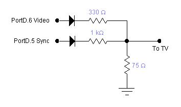
Video DAC
Two bits of a port are used to generate three video levels:
The circuit is shown below.
Graphics primitives
There are a few primitive operations which are nice to have:
The point, line and detection graphics primitives are implemented in the fourth example code below. The fifth code example has improved character generation. I implemented three character generators. The 8x8 and 3x5 pixel character generators are very fast, but have limited placement of characters in the x-direction. The 5x7 character generator has pixel-accurate placement, but is much slower.
All drawing must be done during TV scan lines 230-260 and 1-30 to avoid visual
artifacts (flickering). Drawing is done by writing bits (pixels) into the main
screen array, while the array is not being displayed.
Draw a point
The point code is a function which takes three parameters: an x coordinate
in the range of 0-63, a y coordinate in the range of 0-99, and a color given
as 0 means black, 1 means white, and 2 means invert the pixel. The pixels are
packed into bytes, so there is an addressing step which looks strange. There
are 8 pixels/byte and 8 bytes/line. Thus, the x coordinate has to be divided
by 8 to get the byte number within a line and the y coordinate has to be multiplied
by 8 to get the appropriate group of 8 bytes corresponding to a line. The 1<<(7-(x
& 0x7)) construction isolates (within the byte) which bit must be
set/cleared.
//plot one point
//at x,y with color 1=white 0=black 2=invert
void video_pt((char x, char y, char c)
begin
	//The following odd construction
  	//sets/clears exactly one bit at the x,y location
	i=((int)x >> 3) + ((int)y << 3) ;
 	if (c==1) 	screen[i] = screen[i] | 1<<(7-(x & 0x7));
  	if (c==0)	screen[i] = screen[i] & ~(1<<(7-(x & 0x7)));
  	if (c==2)	screen[i] = screen[i] ^ (1<<(7-(x & 0x7)));
end
Read back a point
The read back code is a function which takes an x coordinate in the range of 0-63, a y coordinate in the range of 0-99, and returns a character with value 1 if the pixel is white and 0 if it is black.
//return the value of one point
//at x,y with color 1=white 0=black 2=invert
char video_set((char x, char y)
begin
	//The following construction
  	//detects exactly one bit at the x,y location
	i=((int)x >> 3) + ((int)y << 3) ;
	return ( screen[i] & 1<<(7-(x & 0x7)));
end
Draw a line
The line drawing code takes two (x,y) coordinates and connects them with a line drawn with a Breshenham algorithm. The Breshenham algorithm avoids all multiplys and divides (except by 2), so it is fast on a small processor. It also ensures a dense line with points in adjacent pixels. The CodeVision compiler control panel must set to allow signed chars.
//plot a line
//at x1,y1 to x2,y2 with color 1=white 0=black 2=invert
//NOTE: this function requires signed chars
//Code is from David Rodgers,
//"Procedural Elements of Computer Graphics",1985
void video_line(char x1, char y1, char x2, char y2, char c)
begin
	char x,y,dx,dy,e,j, temp;
	char s1,s2, xchange;
	x = x1;
	y = y1;
	dx = cabs(x2-x1);
	dy = cabs(y2-y1);
	s1 = csign(x2-x1);
	s2 = csign(y2-y1);
	xchange = 0;
	if (dy>dx)
	begin
		temp = dx;
		dx = dy;
		dy = temp;
		xchange = 1;
	end
	e = (dy << 1) - dx;
	for (j=0; j<=dx; j++)
	begin
		video_pt(x,y,c) ;
		if (e>=0)
		begin
			if (xchange==1) x = x + s1;
			else y = y + s2;
			e = e - (dx << 1);
		end
		if (xchange==1) y = y + s2;
		else x = x + s1;
		e = e + (dy << 1);
	end
end
Draw a character
Three character generators were written. Each will be described below. The 5x7 and 3x5 character sets have limited string-to-video abilities.
8x8 Character Generator. A simple character generator
reads a bitmap stored in flash and copies it into the screen
array. The first few entries of the bitmap array are shown
below, corresponding to the characters 0, 1 and 2. You can discern the character
shape by squinting at the 1/0 table.
flash char bitmap[13][8]={
	//0
    0b00000000,
	0b00111000,
	0b01000100,
	0b01000100,
	0b01000100,
	0b01000100,
	0b01000100,
	0b00111000,
	//1
	0b00000000,
	0b00010000,
	0b00110000,
	0b01010000,
	0b00010000,
	0b00010000,
	0b00010000,
	0b01111100,
	//2
	0b00000000,
	0b00011100,
	0b00100010,
	0b00000010,
	0b00000100,
	0b00001000,
	0b00010000,
	0b00111110,
The actual character generator is shown below. It is limited
to drawing characters which are aligned on byte boundaries. The desired
character is simply copied into the screen array, and is therefore
fast..
// put a character on the screen
// x-cood must be on divisible by 8
// c is index into bitmap for one character
void video_putchar(char x, char y, char c)
begin
	i=((int)x >> 3) + ((int)y << 3) ;
	screen[i]    = bitmap[c][0];
	screen[i+8]  = bitmap[c][1];
	screen[i+16] = bitmap[c][2];
	screen[i+24] = bitmap[c][3];
	screen[i+32] = bitmap[c][4];
	screen[i+40] = bitmap[c][5];
	screen[i+48] = bitmap[c][6];
	screen[i+56] = bitmap[c][7];
end
// put a small character on the screen
// x-cood must be on divisible by 4
// c is index into bitmap
void video_smallchar(char x, char y, char c)
begin
	char mask;
	i=((int)x >> 3) + ((int)y<< 3) ;
	if (x == (x & 0xf8)) mask = 0x0f;
	else mask = 0xf0;

	screen[i] =    (screen[i] & mask) | (smallbitmap[c][0] & ~mask);
   	screen[i+8] =  (screen[i+8] & mask) | (smallbitmap[c][1] & ~mask);
   	 screen[i+16] = (screen[i+16] & mask) | (smallbitmap[c][2] & ~mask);
    	screen[i+24] = (screen[i+24] & mask) | (smallbitmap[c][3] & ~mask);
   	screen[i+32] = (screen[i+32] & mask) | (smallbitmap[c][4] & ~mask);
end

// put a string of small characters on the screen
// x-cood must be on divisible by 4
void video_putsmalls(char x, char y, char *str)
begin
	char i ;
	for (i=0; str[i]!=0; i++)
	begin
		if (str[i]>=0x30 && str[i]<=0x39)
			video_smallchar(x,y,str[i]-0x30);
		else video_smallchar(x,y,str[i]-0x40+12);
		x = x+4;
	end
end
// put a big character on the screen
// c is index into bitmap
void video_putchar(char x, char y, char c)
begin
	char j;
    for (j=0;j< 7;j++)
    begin
        v1 = bitmap[c][j];
        video_pt(x,   y+j, (v1 & 0x80)==0x80);
        video_pt(x+1, y+j, (v1 & 0x40)==0x40);
        video_pt(x+2, y+j, (v1 & 0x20)==0x20);
        video_pt(x+3, y+j, (v1 & 0x10)==0x10);
        video_pt(x+4, y+j, (v1 & 0x08)==0x08);
    end
end

// put a string of big characters on the screen
void video_puts(char x, char y, char *str)
begin
	char i ;
	for (i=0; str[i]!=0; i++)
	begin
		if (str[i]>=0x30 && str[i]<=0x39)
			video_putchar(x,y,str[i]-0x30);
		else video_putchar(x,y,str[i]-0x40+9);
		x = x+6;
	end
end
Example Programs
For the newest version go to the bottom of the page in the Optimization and Bug Fixes section.
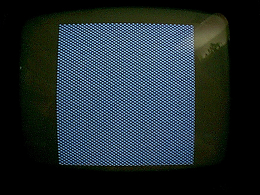
The first code produces a checker board pattern to check for accuracy and stability of the displayed raster. The pattern is hard-coded.
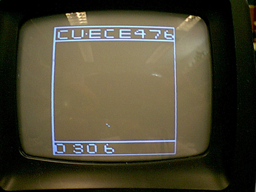
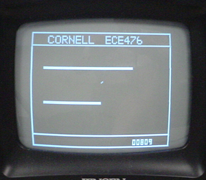
The second test program content consists of points, lines, and text. The lines are hard-coded, and the point drawing stuff is minimal. The vertical and horizontal lines were hard-coded to the edges of the display region. A bouncing ball (the two dots in the lower center, just above the 6) tests for correct write/erase of a point. The 8x8 character generator supports bitmap characters, which are defined in flash memory. The number at the bottom is an elapsed time in seconds.
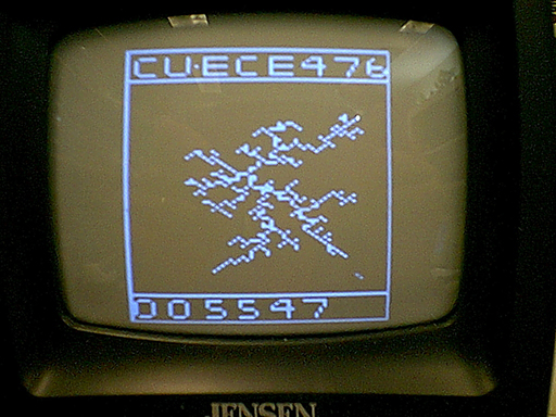
The third program computes a diffusion-limited aggregation (DLA). This was a test of dynamics in the code and required a better version of a function to write/erase a point and a function to read back a point from video memory. The algorithm releases a particle at the edge of the region, which then diffuses randomly until it hits a seed particle in the center of the screen. A new particle is then released and the process repeated. This example took 5547 seconds to compute. The current free particle can be seen in the lower-right of the screen.
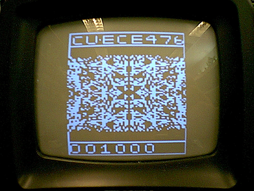
The fourth program implements a fast line generator and cleans up the point, character, and read-back primitives to be more consistent. It uses the line generator to draw a 4-fold symmetric kalidoscope pattern.
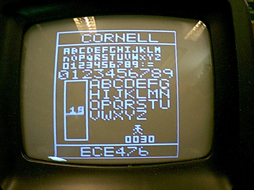
The fifth program implements the very small (3x5) font and a limited string-to-video abilty for the 3x5 and 5x7 fonts. The rectangle at the lower left is an animated "fuel gauge". The animated "stick figure" suggests how to do sprite animation.
Adding Sound
Since most TVs have a sound input, it would be nice to be able to generate some sound from the program. Two modifications of the video program are necessary to generate sound on the Mega163. (Note that sound on the Mega32 is much easier, see the next section.) First, a bit needs to be toggled in the the interrupt which handles the sync generation. Care must be taken to make all conditionals use the same number of cycles, to avoid video jitter. Second, to save a few microseconds, loading resisters for video playback on each line has to be converted to assembler. This example produces a two-octave scale, playing 4 notes/second. The accuracy of the tones is about 1%, which is good enough for sound effects, but will drive some people out of the room. This version of the video program is portable across compiler versions and is compatable with CodeVision version 1.23.7.
The following Matlab code generates the required counts, assuming that the sync interrupt will toggle a bit. The first column of the output is the frequency of the note. The second column is the note duration in units of 63.625 microseconds. The third is the relative error. Between C3 and C6, all note frequencies are within 1% error except for F5 which is flat by 2%.
The output port pin should be connected to ground by a 5 Kohm resistor. The TV should be connected across the resistor. The resistor is necessary because the TV is AC coupled and will slowly charge up and cut off the audio.
 %Generate counts for notes c3 to c6
 %in units of 63.625 microseconds
fmax = 1/63.625e-6;
notes=[130.8 146.8 164.8 174.6 196 220 246.9 ...
        261.6 293.7 329.6 349.2 392 440 493.9 523.3 ...
        587.3 659.3 698.5 784 880 987.8 1046.5];
r = (fmax./notes);

for i=1:length(r)
    fprintf(1,'%6.1f%6.1f%10.4f\n',notes(i),round(r(i)),(r(i)-round(r(i)))/r(i));
end

%frequency, count, relative error
 130.8 120.0    0.0013  C3
 146.8 107.0    0.0006
 164.8  95.0    0.0039
 174.6  90.0    0.0002
 196.0  80.0    0.0024
 220.0  71.0    0.0062
 246.9  64.0   -0.0054
 261.6  60.0    0.0013  C4
 293.7  54.0   -0.0091
 329.6  48.0   -0.0066
 349.2  45.0    0.0002
 392.0  40.0    0.0024
 440.0  36.0   -0.0078
 493.9  32.0   -0.0056
 523.3  30.0    0.0012  C5
 587.3  27.0   -0.0089
 659.3  24.0   -0.0068
 698.5  23.0   -0.0222  F5 2% error!
 784.0  20.0    0.0024
 880.0  18.0   -0.0078
 987.8  16.0   -0.0056
1046.5  15.0    0.0012  C6
Optimization and Bug fixes
Mega32 with sound 5 May 2003 Current Version
Changes/improvements/bugs:
Mega32 version 27 March 2003
Changes/improvements/bugs:
Mega32 version. 5 March 2003
Changes/improvements/bugs:
delay_us() calls.chip signature
checkNewest Mega163 version. 28 Feb 2003
Bug fixes:
colon character prints
correctly.signed char box
in the compiler.Optimization:
Copyright Cornell University Jan 2003