
Generate interactive real-time 3D stereograms on your very own FPGA!
We developed an animated single image random dot stereogram (SIRDS) generation platform. Our platform can generate a 3D stereo image from a depth map which records the distance to each pixel within the image. The depth map can be a dynamic scene with varying depth values over time. Each horizontal line of the stereogram image is generated on the fly from the corresponding line of the depth map. The image is displayed on a VGA screen at a resolution of 640x480 pixels. The user can toggle between the display of the depth map and the stereogram with the DE2 board switches. The user can interact with the depth map itself with the DE2 board keys.
When we began looking at final projects, we wanted to do something entertaining. Technical competence is obviously the most important aspect of the project, but we wanted ours to be interesting to look at. The classroom lectures on the human visual system and stereograms inspired us to make our own stereogram generator. However, the traditional static image is a poor use of the FPGA's processing capability. We wanted to build a real-time stereogram generator which would support changing depth maps and user interaction.
The central idea behind stereograms is that the paths from an object to each eye are different. If the eyes maintain a certain focal depth, they cannot tell the difference between a single point at that depth and a pair of points along the paths to that depth. The stereogram tricks the eye by correlating the pixels along these paths and making the brain believe that the eyes are focused at a particular depth when they are not.
There are two spaces that are important when thinking about a stereogram. They are the virtual surface and the screen surface. The virtual surface is the 3D image that the stereogram encodes. It exists entirely behind the screen and consists of a height value for each point on the surface. Screen surface is the 2D space of the screen. Since the stereogram relies on each eye seeing a different image, each point on the virtual surface maps to two points on the screen surface. The distance between the screen points is a function of the virtual surface point's height, the background depth, and the observer's eye separation and distance.
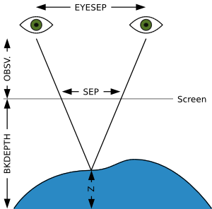
Background depth specifies the perceived distance between a virtual height of zero and the surface of the screen in pixels. Observer distance specifies the expected number of pixels between the screen and the viewer. Eye separation specifies the expected number of pixels between the centers of the viewer's pupils. These parameters determine how the pixels will be linked together for 3D viewing. The latter two values are approximate, but the more accurate they are to the viewer's actual position and physiology, the easier it will be for the viewer to perceive the image.
The following equation can be used to calculate the separation of two linked pixels on the screen surface:

The generation of a stereogram consists of many steps, but it is not very complicated. The process begins with a depth map. The desired scene is represented as a field of height values. The dark areas are far away, with black representing the background. Lighter areas are closer to the viewer, with pure white representing the nearest possible point.
Once the depth map is known, a link buffer must be created. The purpose of this buffer is to capture the relationships between pixels. The array is as wide as the screen and is initialized such that each element of the array stores the value of its index. The array elements are then linked to each other. For each point on the depth map, the separation of the screen surface pixels is calculated. The screen pixel that is separation/2 pixels to the right of a virtual surface point is linked to the screen pixel that is separation/2 pixels to the left of the point. The linking process consists of setting the link buffer element corresponding to the right pixel to the value of the link buffer corresponding to the left pixel.
With the pixels linked, the last step is to assign values to them. If a link buffer element contains its own index, then it is not associated with any other element. The corresponding pixel therefore receives a random value. If a link buffer element contains a different index, then it has been associated with a pixel to its left. The corresponding right pixel therefore gets the value of that left pixel. The proceedure works it way from the left side of the link buffer to the right, assigning either a random value or a linked value to each pixel.
This algorithm will generate a single line of screen values for display. To create a full frame of stereogram, the process must be repeated for each screen line. If the depth map is static, there is no need to go any further, but if it is changing, then a new frame must be created for each update of the map.
We decided to implement our design entirely in hardware. We started with a sequential algorithm, so it would have been more straightforward to try to calculate our SIRDS in a NIOS II processor. However, that would have made it difficult or impossible to achieve the real-time and animation aspects of our design. We spent a lot of effort figuring out how to convert from sequential operation to parallel operation, but it was worth the speed up. With everything in hardware, we were able to implement the algorithm as fast was necessary.
We initially based our code on a C++ SIRDS generator we found at [1]. Our first implementation was a direct conversion to Verilog. Since that algorithm was sequential, we used a large state machine to do the SIRDS generation in a similar sequential manner. We stored both the depth-map and stereogram in SRAM as 8-bit 320x240 images. This approach had several serious limitations. The most serious limitation was speed: computing the stereogram entirely sequentially was a slow process that took about one third of a second. The resulting 3Hz framerate was too slow to allow for convincing animation. Also, the storage capacity of the SRAM prevented the generation of full VGA resolution stereograms.
We investigated condensing the state machine into fewer states so that each stereogram pixel could be computed in fewer cycles. However, the generation of a single stereogram pixel requires several independent steps that can only be executed in series. On top of that, our implementation required four memory accesses per pixel (excluding the read required by the VGA controller): a write and read of the depth-map, and a write and read of the stereogram. All combined, the generation of a single stereogram pixel took at least a dozen cycles.
After consideration, we realized that the depth-map didn't need to be saved, since each line of the stereogram was generated independently of every other line. Therefore, only a single line needed to be in memory at a time. A single line fit easily within the FPGA's onchip M4K blocks, and thus two memory accesses could be eliminated. Furthermore, by parallelizing the generation of multiples pixels, we thought that we could significantly increase the rate at which pixels could be generated.
We wanted to pipeline our SIRDS generator, but since each pixel still required two memory accesses we couldn't do a true pipeline due to the structural hazard. Therefore, we designed a two stage pseudo-pipeline where each stage was actually a state-machine. This configuration was able to compute a stereogram pixel in four clock cycles, with a throughput of a pixel every two cycles. At a resolution of 320x240, this was fast enough to regenerate stereograms at VGA framerate.
Although we had achieved full 60Hz update rate, we were still unable to increase to full VGA resolution. In order to reach 640x480 resolution, we would need a throughput of one stereogram pixel per clock cycle. With two memory accesses per pixel (again excluding the read required by the VGA controller), this was simply not possible if the SRAM was clocked at the VGA control clock. We considered clocking the SRAM faster than the VGA control clock, but our real breakthrough was realizing that we didn't actually need SRAM at all. There was no particular reason that the VGA controller had to operate out of SRAM. Instead, it would be possible generate pixels on the fly. By removing the structural hazard imposed by SRAM, a true pipeline was possible.
We designed an eight stage pipeline that took a pair of x and y coordinates as input to the first stage and produced a pixel value as the output of the eighth stage. The pipeline takes advantage of the fact that a pixel can only be linked to a pixel to the left of it. This means that the color of pixel (x,y) on the stereogram is only dependent on points (x'<x,y'=y) on the depth-map. Therefore, only the part of the line left of (x,y) needs to be linked before pixel (x,y) of the stereogram can be determined. The pipeline stages are summarized in the table below:
| Stage | Inputs | Operation | Outputs |
|---|---|---|---|
| 1 & 2 | x0, y0 | Generate height (z1) at point (x0,y0) | x2, y2, z2 |
| 3 & 4 | x2, y2, z2 | Compute separation (sep) for point (x2,y2) | x4, y4, z4, sep |
| 5 | x4, y4, z4, sep | Compute left & right pixels corresponding to point (x4,y4) | x5, y5, z5, left, right |
| 6 | x5, y5, z5, left, right | Link right pixel to left pixel; follow link of (x5,y5) | x6, y6, z6, link_x6 |
| 7 | x6, y6, z6, link_x6 | Read the color of pixel (link_x6,y6) | x7, y7, z7, link_x7 |
| 8 | x7, y7, z7, link_x7 | Determine color of pixel (x7,y7) | color of (x7,y7) |
The first two stages simply take as input depth-map (x,y) coordinates and determines the height z corresponding to those coordinates. Two stages are used in order to allow for complex computation that cannot be performed in a single clock cycle. Using the height computed in the first two stages, the third and fourth stages determine the separation of the stereogram pixels corresponding to that height. Again, the calculation is too complex to be done in a single cycle, so it is spread over two. The first cycle (third stage) computes the numerator and denominator of Equation 1 separately. The second cycle (fourth stage) then divides the numerator by the denominator. The separation is then passed into the fifth stage, which computes the left and right pixels coordinates corresponding to the original depth-map coordinates.
The left and right pixel coordinates are linked together in the sixth stage. This is perhaps the most complicated stage. Since each pixel must initially be linked to itself, the sixth stage maintains two link buffers. It initializes one while using the other, alternating between the two each line. In addition to linking the right pixel to the left, the sixth pipeline stage also follows the link of the pixel at coordinates (x,y) that were passed into the first stage.
The seventh stage uses the coordinates of the linked pixel determined in the sixth stage and reads the color of that pixel. This color is passed into the eighth stage which decides the color of the pixel at (x,y). If the pixel is linked to itself, then a random color is assigned to that pixel. Otherwise the color from the linked pixel as read in the seventh stage is used. The color of pixel (x,y) is stored in two separate buffers in M4K. One buffer is used for reading the color of a pixel in the seventh stage, and the other is used by the VGA controller.
The pipeline is started at the end of each H-sync by passing in coordinates (0,y), where y is the current line that will be displayed by the VGA controller. Each cycle thereafter the x-coordinate is incremented by one until the entire line has been generated. The second buffer described above allows the SIRDS generator and VGA controller to operate independently. This is true as long as they remain synchronized to the same line and the length of the pipeline is less than the back porch of the VGA signal. Since the back porch is 40 cycles of VGA_CTRL_CLK, 32 additional pipeline stages could probably be added without a problem.
The opportunity to add more pipeline stages allows for a great deal of possible future development. The SIRDS algorithm as implemented is about as simple as possible. More pipeline stages would allow it to be enhanced using oversampling or hidden object removal (see [1] for more details). Another possibility is that the SIRDS pipeline could be prefixed with a deep 3D GPU pipeline that could generate more interesting 3D scenes on the fly.
We achieved our goal of making an interactive animated single image random dot stereogram generator. We began with a sequential algorithm in C++ and were able to first convert it into a multi-cycle SIRDS generator and from there into a real-time pipelined generator. We were able to upgrade our display from a static 320 by 240 pixel image to an animated 640 by 480 pixel image by generating the depth map on the fly and then discarding it. An example is below with two large squares in the middle of the screen, a small square near the bottom-right, and a long rectangle across the top. Click on the image to see a bigger (and clearer) version:
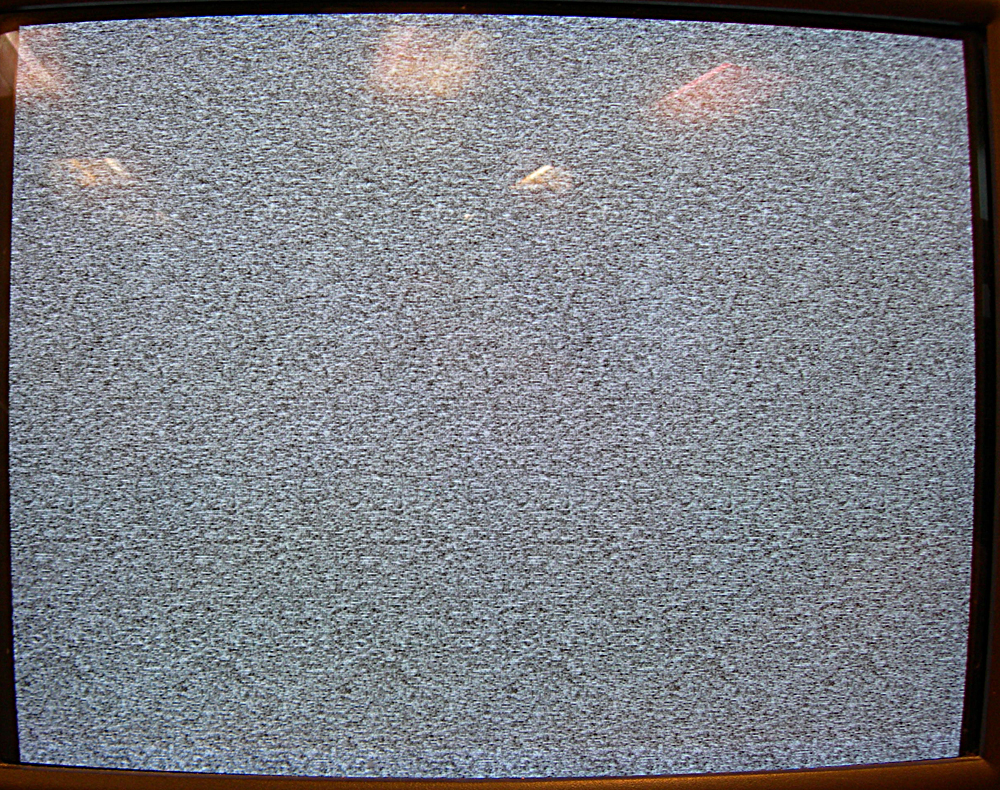
A movie shows the bottom square moving left-right and the rectangle at the top moving deeper-shallower.
We had a lot of trouble with VGA timings in our early implementation of the SIRDS generator. Since we were generating an entire screen line at once, we had to make use of the horizontal sync to have any hope of keeping up with the refresh rate of the screen. Unfortunately, we had so many states and memory accesses to process we could only update the screen at about 3 Hz. When we moved to the pipelined design and M4K block storage, we could generate each pixel's value as it was requested by the VGA, so we were able to match the timing exactly.
There are some issues that we had to deal with when we were animating our SIRDS. Since we were generating a completely new random image for each frame, there was no direct spatial consistency between frames. The mind's lock on the virtual surface was not interrupted, because the links between pixels were still the same for most of the image, but all of the colors were different. This was good because it was not possible to see what was happening on the screen without locking on to it. However, it made it difficult to pin down the edges of objects in the virtual space.
The level of interactivity we achieved was good in some senses, but lacked in others. We were able the use the keys to change the depth map as it was generated. This gave us a very easy to use and responsive system. On the other hand, there are only so many buttons on the DE2 board and the hardware level manipulations that we could assign to the buttons were not as interesting as a more elaborate control scheme might have been.
Safety is of some concern in our project. Staring at screens of flashing lights has been linked to seizures and migraines, and the abnormal nature in which the user views the screen could cause eye strain. The latter concern is a minor one. If the viewer is uncomfortable looking at the screen then there is no reason to continue to do so. The device is meant for entertainment, not long term use. As the former two health risks, we can only offer a warning and hope that those afflicted by such conditions know that they are at risk and avoid our project.
We do not know how many people will be able to use our project. Magic Eye estimates that 95% of people are able to see their images, so our project should be accessible to the majority of the population.
Overall we are satisfied with our project. It is an effective, fast implementation of the algorithm. It offers smooth animations and responsive controls. It would have been nice to have had time to add a slicker demo element, but the core is solid.
The most disappointing shortcoming of the project is that we were not able to implement a mechanism for creating complex depth maps. The current implementation relies on generating the depthmap in hardware. This limits the shapes we can display to ones that are easy to describe mathematically. Originally, we were also limited to a single cycle to do any generation. When we added more pipeline stages, that limitation went away.
The only Verilog code that we did not write was the Terasic wrapper module that does all of the dirty work of creating and connecting the pin signals. We based our first implementation of the SIRDS generator on a C++ algorithm we found on a website, but the conversion to Verilog and subsequent modification into a pipelined processor was entirely our work.
Copyright (c) 2007: Adam Hart, Morgan Jones.
Logo contains elements derived from the work of Randall Munroe (www.xkcd.com) and is used in accordance with the terms of the Creative Commons Attribution-NonCommercial 2.5 License.