Parallelized Knuth-Morris-Pratt Search Algorithm
Chris Dolen
Robert Zimmerman
Introduction
Our project was to implement a highly parallelized and modular version of the Knuth-Morris-Pratt algorithm. The main objective of the project was to demonstrate the implementation of parallel units capable of performing this algorithm on the FPGA. The secondary objective was to develop a modular platform for parallelization of serial algorithms that require a short input string that varies often and a large database that is fairly static.
Knuth-Morris-Pratt Algorithm
The algorithm we chose to parallelize is called the Knuth-Morris-Pratt algorithm, as it was invented by Donald Knuth, Vaughan Pratt, and J. H. Morris. The algorithm is used to search for a given string in a longer string or set of strings. It is better than the brute force algorithm of comparing characters in the strings by moving 1 character at a time in the set of strings – it skips a subset of the string if a partial match has already been found. A link to the paper describing this algorithm is located in the references section. The example below is based on an online example that is derived from this paper.
Example of the Algorithm
This section shows an example of the algorithm in action. First let’s create our string that we want to check for a possible match. This string we will call the database. It can be any series of characters. We also need a string that we are searching for. This string is called the search string. We will also have two index variables, x and i. x will be the current position we are looking at in the database, and i will be the current character we are matching in the search string. In order to skip characters that have already been matched, a table also needs to be created. So let’s create an array called table, and index with the variable i. The index here is the same I as previously mentioned. Now we can define our database and our search string:
Database: ABC ABCDAB ABCDABCDABDE
Search string: ABCDABD
The table is initialized to all 0’s. It needs to be computed first, so that it can be referenced to bypass recomparing partial matches. Here is the pseudo code of the table building algorithm, taken from Wikipedia.
algorithm kmp_table:
input:
an array of characters, W (the word to be analyzed)
an array of integers, T (the table to be filled)
output:
nothing (but during operation, it populates the table)
define variables:
an integer, i ← 2 (the current position we are computing in T)
an integer, j ← 0 (the zero-based index in W of the next character of the current candidate substring)
(the first few values are fixed but different from what the algorithm might suggest)
let T[0] ← -1, T[1] ← 0
while i is less than the length of W, do:
(first case: the substring continues)
if W[i - 1] = W[j], let T[i] ← j + 1, i ← i + 1, j ← j + 1
(second case: it doesn't, but we can fall back)
otherwise, if j > 0, let j ← T[j]
(third case: we have run out of candidates. Note j = 0)
otherwise, let T[i] ← 0, i ← i + 1
Our code was based off this pseudo code, so understanding how it works is important. First of all, you can see that table[0] = -1, and table[1] = 0. Those two table values are always set to these initial conditions. So our table looks like this:
|
i |
0 |
1 |
2 |
3 |
4 |
5 |
6 |
|
Search String |
A |
B |
C |
D |
A |
B |
D |
|
Table[i] |
-1 |
0 |
0 |
0 |
0 |
0 |
0 |
What we’re trying to do is fill in the table so that a repeating pattern in the search string is noted. As you can see, there is a repeating pattern of AB in the search string. Knowing this will make the searching of the database faster. The table building algorithm helps us find these repeating patterns. So, starting at i=2, we look at (i-1) which is a B. Now the search string is checked to see if this character repeats anywhere, starting at index 0 (referred to as j in the Wikipedia pseudo code). Index 0 (j=0) is A, which is not equal to B. Now we check to see if j > 0, which it is not. Therefore we determine that Table[2] = 0. For i=3, we look at (3-1) which is C, and not equal to A. So the same thing happens, and Table[3] = 0. When i=4, we compare D to A, and they are not equal, so Table[4] = 0. But, when i=5, we compare A to A, and they are equal. This means the variable j is incremented by 1, and Table[5] = 1. Now, when i=6, B (at i-1) is compared to B (at j, which is now 1). Again, these are equal. So j is incremented once more, and now Table[6] = 2. This is the end of the search string, so the table building algorithm is over. Our table now looks like this:
|
i |
0 |
1 |
2 |
3 |
4 |
5 |
6 |
|
Search String |
A |
B |
C |
D |
A |
B |
D |
|
Table[i] |
-1 |
0 |
0 |
0 |
0 |
1 |
2 |
You might notice that even though the partial match starts at i=4, its table value is still a 0, and a 1 isn’t in the table until the following character, at i=5. You might also notice that ABD is not a repeating pattern, yet D (at i=6) has a non-zero value in the table. This is just how the table building algorithm works. It will become clearer once we finish the example of the search algorithm. For now, just remember that a 1 in the table means the previous search string character is the beginning of a partial match, that the partial match continues as long as the table values keep incrementing, and that the maximum value in an incrementing sequence in the table is where the partial match fails. For example, our partial match above ends at i=5, but the highest value in the table is 2, which is at i=6. So the partial match failed at i=6.
Now to continue with the search algorithm. The pseudo code for this algorithm, from Wikipedia, is shown below:
algorithm kmp_search:
input:
an array of characters, S (the text to be searched)
an array of characters, W (the word sought)
output:
an integer (the zero-based position in S at which W is found)
define variables:
an integer, m ← 0 (the beginning of the current match in S)
an integer, i ← 0 (the position of the current character in W)
an array of integers, T (the table, computed elsewhere)
while m + i is less than the length of S, do:
if W[i] = S[m + i],
let i ← i + 1
if i equals the length of W,
return m
otherwise,
let m ← m + i - T[i],
if i is greater than 0,
let i ← T[i]
(if we reach here, we have searched all of S unsuccessfully)
return the length of S
Here we have our database and search string:
|
x |
0 |
1 |
2 |
3 |
4 |
5 |
6 |
7 |
8 |
9 |
10 |
11 |
12 |
13 |
14 |
15 |
16 |
17 |
18 |
19 |
20 |
21 |
22 |
|
DB |
A |
B |
C |
|
A |
B |
C |
D |
A |
B |
|
A |
B |
C |
D |
A |
B |
C |
D |
A |
B |
D |
E |
|
i |
0 |
1 |
2 |
3 |
4 |
5 |
6 |
|
|
|
|
|
|
|
|
|
|
|
|
|
|
|
|
|
SS |
A |
B |
C |
D |
A |
B |
D |
|
|
|
|
|
|
|
|
|
|
|
|
|
|
|
|
To begin with, x and i start at 0, and the first characters of the database and search string are compared. A and A match, so the algorithm continues comparing. B and B match, C and C match, but “space” and D do not match. When this occurs, the table is checked to see what should be done next. x is marking the beginning of the current match in the database, meaning the first place we found a character match. Right now it’s 0, but when this match failed, it gets assigned x + i – Table[i]. x is 0, i is the position of the current character in the search string, which is 3, and Table[3] = 0. So x is now 3. i becomes Table[i], which is again 0. So now our progress looks like this:
|
x |
0 |
1 |
2 |
3 |
4 |
5 |
6 |
7 |
8 |
9 |
10 |
11 |
12 |
13 |
14 |
15 |
16 |
17 |
18 |
19 |
20 |
21 |
22 |
|
DB |
A |
B |
C |
|
A |
B |
C |
D |
A |
B |
|
A |
B |
C |
D |
A |
B |
C |
D |
A |
B |
D |
E |
|
i |
|
|
|
0 |
1 |
2 |
3 |
4 |
5 |
6 |
|
|
|
|
|
|
|
|
|
|
|
|
|
|
SS |
|
|
|
A |
B |
C |
D |
A |
B |
D |
|
|
|
|
|
|
|
|
|
|
|
|
|
As you can see, the algorithm skipped checking x=1 and x=2, as it knows there is no partial match there. This was determined by the help of the table. If there were a partial match there, the table value at i=3 (the location where the string matching failed) would have been non-zero. As we can see by looking at our array, the next location we really want to be looking at is x=4, which is where the next A is. This happens after one more step. A is compared to “space”, and since it is not a match, the search string is shifted one more place.
|
x |
0 |
1 |
2 |
3 |
4 |
5 |
6 |
7 |
8 |
9 |
10 |
11 |
12 |
13 |
14 |
15 |
16 |
17 |
18 |
19 |
20 |
21 |
22 |
|
DB |
A |
B |
C |
|
A |
B |
C |
D |
A |
B |
|
A |
B |
C |
D |
A |
B |
C |
D |
A |
B |
D |
E |
|
i |
|
|
|
|
0 |
1 |
2 |
3 |
4 |
5 |
6 |
|
|
|
|
|
|
|
|
|
|
|
|
|
SS |
|
|
|
|
A |
B |
C |
D |
A |
B |
D |
|
|
|
|
|
|
|
|
|
|
|
|
Now we begin again. Starting at x=4, A=A, B=B, C=C, D=D, A=A, B=B, but a failure occurs at i=6 where D is not equal to “space”. The table is consulted, and Table[i] when i=6 is 2. Therefore x = x + i – Table[i], or 4 + 6 – 2, which is 8. So our array now looks like this:
|
x |
0 |
1 |
2 |
3 |
4 |
5 |
6 |
7 |
8 |
9 |
10 |
11 |
12 |
13 |
14 |
15 |
16 |
17 |
18 |
19 |
20 |
21 |
22 |
|
DB |
A |
B |
C |
|
A |
B |
C |
D |
A |
B |
|
A |
B |
C |
D |
A |
B |
C |
D |
A |
B |
D |
E |
|
i |
|
|
|
|
|
|
|
|
0 |
1 |
2 |
3 |
4 |
5 |
6 |
|
|
|
|
|
|
|
|
|
SS |
|
|
|
|
|
|
|
|
A |
B |
C |
D |
A |
B |
D |
|
|
|
|
|
|
|
|
Notice what has happened here. The search string skipped x=5, 6, and 7, and the algorithm is now starting at x=8, where a potential match could possibly begin. You can see this match also fails, so the next section the algorithm will check is at x=11.
|
x |
0 |
1 |
2 |
3 |
4 |
5 |
6 |
7 |
8 |
9 |
10 |
11 |
12 |
13 |
14 |
15 |
16 |
17 |
18 |
19 |
20 |
21 |
22 |
|
DB |
A |
B |
C |
|
A |
B |
C |
D |
A |
B |
|
A |
B |
C |
D |
A |
B |
C |
D |
A |
B |
D |
E |
|
i |
|
|
|
|
|
|
|
|
|
|
|
0 |
1 |
2 |
3 |
4 |
5 |
6 |
|
|
|
|
|
|
SS |
|
|
|
|
|
|
|
|
|
|
|
A |
B |
C |
D |
A |
B |
D |
|
|
|
|
|
Here, the match is almost successful, but still fails. So the algorithm will now begin again at x = 15, with the help of the table pointing out the partial match again.
|
x |
0 |
1 |
2 |
3 |
4 |
5 |
6 |
7 |
8 |
9 |
10 |
11 |
12 |
13 |
14 |
15 |
16 |
17 |
18 |
19 |
20 |
21 |
22 |
|
DB |
A |
B |
C |
|
A |
B |
C |
D |
A |
B |
|
A |
B |
C |
D |
A |
B |
C |
D |
A |
B |
D |
E |
|
i |
|
|
|
|
|
|
|
|
|
|
|
|
|
|
|
0 |
1 |
2 |
3 |
4 |
5 |
6 |
|
|
SS |
|
|
|
|
|
|
|
|
|
|
|
|
|
|
|
A |
B |
C |
D |
A |
B |
D |
|
On this run, a match is indeed found. This is determined when every character in the search string has been matched with a subset of characters in the database.
Parallelizing The Algorithm
In the above example, there was only 1 substring in the database. Let’s assume the database looks more like this:
ABC ABCDABC ABCDABEE
BBCBABCDABC ABCDABEEABD
AECABBDABCCABCDABEEBBACDE
DBCABEDADC ABCDABCC
CDCABBDAACBABCDABED
ABDABBBCDAC
ABCBCDABCBCDABEEDEDCA
etc… Here we have multiple strings with differing lengths. Instead of searching each of these substrings one by one, they could be searched in parallel, if there were multiple hardware units available to do this. An example of wanting to do this might be something like Google, where you enter a search term and multiple terms inside a giant database need to be searched. While multiple CPU’s could also do the job, for the same amount of chip real estate and power consumption, you could have more specialized search units running on an FPGA. This is the basis of our project.
High Level Design
System Requirements
For this project, the following design specification requirements were developed:
1. The design shall implement the Knuth-Morris-Pratt algorithm for string searching.
2. The design shall receive data to be searched from a file on the user’s computer.
3. The design shall accept search string input from the user.
4. The design shall report the location(s) in the data to be searched of the search string to the user.
5. The design shall use the DE2 Board and Cyclone II FPGA.
Block Diagram
To transfer data over to the FPGA, we decided to use the Ethernet port on the FPGA. We chose to use a Nios II processor to interface the Ethernet port with the hardware that runs the algorithm. We chose to use the Nios IDE terminal to view the search results.
In order to send data over the Ethernet port, we used a program written in C# (included in the appendix) that utilized a raw Ethernet driver. A homemade crossover cable was used to connect the computer to the DE 2 board.
The system structure is as follows:
We implemented the Knuth-Morris-Blocks in Verilog. These blocks all received their data from the Nios II.
Program/Hardware Design
C# Program
For this part of the design, we mirrored closely a design by Eric Brumer and Brent Patane for their Head Related Transfer Function Project. Eric was able to provide a link to a raw Ethernet packet driver that allowed us to directly write packets to the Ethernet port from C#. This eliminated a lot of the overhead that would have been incurred by using a higher level protocol, such as UDP or TCP.
In order to interface our C# code with the Nios II, we defined the following protocol for packets:
|
Byte in Packet |
Description |
|
0-5 |
Destination MAC address. Should always be all 0xFF for “broadcast”. |
|
6-9 |
Part of the source MAC address. Value is ignored by the receiver, but 0x55 is generally used in our code. |
|
10-11 |
Packet type. The following are valid packet types: · 0x0000 – Reset the K-M-P database on the Nios II · 0xAAAA – Nios II will print the checksum of all data packets received so far. The checksum is calculated by adding all the 16 bit words in the data stream and returning the lower 16 bits · 0xBBBB – the data portion of the packet is a search string (null terminated) · 0xCCCC – a “go!” packet (not used) · Any other packet type is a data packet. The data in the data section of the packet should be appended to the database in SDRAM by the Nios II |
|
12-13 |
Protocol. Should always be 0x8000 (most significant byte first) |
|
14-1023 |
Data. Discarded if this is not a data or search string packet. |
|
1024-1027 |
Packet checksum. This is sent automatically by the packet driver (the C# code only needs to send the first 1024 bytes) and ignored by the NiosII. |
This protocol was designed to follow basic data link layer definitions so as not to trip up the Ethernet controller on the DE2 board. All packets are a fixed size of 1024+4 bytes of checksum automatically appended by the Ethernet driver.
Sending data from the C# program was straightforward. By making modifications to the sample code on the HRTF site, we were able to obtain the following flow:
1. Open the NDIS raw packet driver
2. Open the selected network adapter
3. Send a reset packet
4. Wait 50ms
5. Open the database file
6. Send 1024 bytes of the database file as a data packet
7. Update the internally calculated checksum to reflect the data in the packet
8. Wait 1ms
9. If the file has more data, go back to step 6
10. Send the print checksum packet (this allows us to compare checksums)
11. Prompt the user for a search string
12. Send the search string in a search string packet
13. Send the go packet (not necessary, originally used for debugging)
The 1ms delay was necessary to ensure data was not lost by the Nios II. With some tweaking of the Ethernet ISR, this could probably be eliminated. The full code is included in the appendix.
Nios II Design
Our Nios II used the following components:
|
Component Type |
Name |
Descirption |
|
JTAG UART |
jtag_uart |
Used to communicate with the user and for debugging |
|
SDRAM Controller and SDRAM |
sdram_0 |
8MB of RAM used for storing the database. This was allocated as the upper part of memory and we told our Nios II project to put variables into SDRAM using the project settings. |
|
SRAM |
sram_0 |
512KB of SRAM used for program memory. We assigned the memory address to 0x000000 and set the reset vector appropriately to allow this space to be exclusively for program memory. |
|
DM9000A Ethernet Controller |
dm9000a |
Used to interface with the Ethernet port. This block was taken off of the Altera DE2 CD-ROM. |
|
Parallel Output |
module_sel |
16 bit bus to select the appropriate K-M-P block when writing memory and reading results. |
|
Parallel Output |
data_out |
16 bit bus for data output to K-M-P block SRAM blocks. |
|
Parallel Output |
mem_addr |
16 bit bus to select memory address to write to in K-M-P SRAM. |
|
Parallel Output |
control_flags |
8 bit bus with control flags. Bits are
all active high: 1 – Write enable for search string SRAM 2 – Write enable for table SRAM 3 – Reset line for all K-M-P blocks 4 – Unused 5 – Unused 6 – Unused 7 – Unused |
|
Parallel Input |
result_in |
16 bit input from the K-M-P block selected by module_sel. Bit 15 is the done bit, indicating the module has completed searching. The lower byte is the resulting position of the search string in the module’s database, or 0xFF if it is not found. This byte is only valid if the done bit is high. The other bits are undefined and not guaranteed to be zero. |
Verilog and Knuth-Morris-Pratt
For this part of the design, we chose to use the Nios II as our central control block. The Nios II was responsible for ferrying data from SDRAM to the various search units and reading their results as they finished. It was also responsible for precomputing the table.
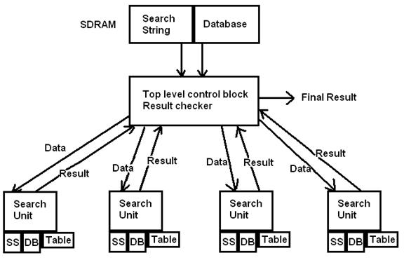
In order to store data, such as the database, string, and table, some sort of storage needed to be used in the search units. SRAM or SDRAM couldn’t be used; we needed parallel access to the data, potentially every cycle. So, M4K blocks were used. Each search unit uses 3 modules of this data memory, called ram_infer. This block was taken from the Altera HDL style manual, pages 6-17:
// data memory:
// single read and write
// taken from Altera HDL style manual page 6-17
// Synchronous RAM with Read-Through-Write Behavior
// and modified for 8 bit access
// of 256 bytes
module ram_infer (q, a, d, we, clk);
output [7:0] q;
input [7:0] d;
input [7:0] a;
input we, clk;
reg [7:0] read_add;
reg [7:0] mem [255:0];
always @ (negedge clk) begin
if (we) mem[a] <= d;
read_add <= a;
end
assign q = mem[read_add];
endmodule
Notice that these blocks are clocked on the negative edge. This is so the inputs can be changed on a positive edge, the read and/or write can occur on the negative edge, and the result is ready on the next positive edge.
Each search block was instantiated identically, using a generate loop. This allowed us to change the number of blocks by changing a single parameter and recompiling the design.
generate
genvar i;
for (i = 0; i < SEARCH_BLOCKS; i = i + 1)
begin : blocks
searchblock u(CPU_CLK, ram_din, nios_ram_addr, ((module_sel == i) ? ram_we : 0), ss_we, tbl_we, result[i], complete[i], hc_reset);
end
endgenerate
These variables were hooked to the PIO ports of the Nios II as follows (see the code in the Appendix for details):
|
module_sel |
Hooked directly to the module_sel net |
|
data_out |
Hooked to the ram_din net |
|
mem_addr |
Hooked to the nios_ram_addr net |
|
control_flags |
Bits connected as follows: 1 – ss_we 2 – tbl_we 3 – hc_reset 4 – Unused 5 – Unused 6 – Unused 7 – Unused |
|
result_in |
Bit 15 is hooked to complete[module_sel] Bits 7 through 0 are hooked to result[module_sel] Bits 14 through 8 are floating |
Note that since the search string and table strings are the same for all search blocks, we used the same enable lines for all blocks. This allowed us to write to all search blocks simultaneously. The database, however, is different for each search block, so only the module selected by module_sel receives the write enable signal to allow serial transfer.
Search Module
The search module is based off of the algorithm described in the introduction. The Verilog code is included below and is available in the appendix.
Inputs to the module include a clock, data bus, address bus, write enables for each ram block, and a reset. Outputs include the result and a flag indicating the block is done and the result is valid.
module searchblock (CLK, din, addr, ram_we, ss_we, tbl_we, result, complete, reset);
input CLK;
input [15:0] din, addr; //input data bus
input ram_we; //database write enable
input ss_we; //search string write enable
input tbl_we; //table write enable
input reset; //hold off searching until low
output [15:0] result; //address of match
output complete; //searching is done
Defined next are output busses from the ram blocks, registers for the output and state, registers that correspond to the i and j indices in the example, and states.
wire[7:0] ss_output, tbl_output, db_output;
reg complete;
reg [3:0] searchState;
reg [15:0] result;
reg [15:0] tbl_addr, ss_addr, db_addr; //db_addr = i index, tbl and ss_addr are j index
parameter init = 0, search = 1, done = 2, ramwait = 3;
Next is the state machine. There is a reset condition to hold the block from starting until the Nios II is ready. There is an initialize state which sets variables to zero, a search state which does the searching, and a state to wait for the ram blocks to settle. The search state was based off of the example c code. When the search is complete, the machine sits in the done state.
always @(posedge CLK)
begin
if (reset == 1)
begin
searchState <= init;
end
else
begin
case (searchState)
init:
begin
db_addr <= 0;
ss_addr <= 0;
tbl_addr <= 0;
searchState <= ramwait;
end
search:
begin
if (ss_output == 0 && ss_addr[7:0] != 8'hff) //string is found (account for index of -1)
begin
searchState <= done;
result <= db_addr - ss_addr;
complete <= 1;
end
else if (db_output == 0) //string not found (db exhausted)
begin
searchState <= done;
result <= -1;
complete <= 1;
end
else if (ss_addr[7:0] == 8'hff || db_output == ss_output) //if j < 0 || ss[j] == db[i]
begin
//i++;
//j++;
db_addr <= db_addr + 1;
ss_addr <= ss_addr + 1;
tbl_addr <= ss_addr + 1;
searchState <= ramwait;
end
else
begin
//j = table[j];
tbl_addr <= tbl_output;
ss_addr <= tbl_output;
searchState <= ramwait;
end
end
ramwait: //not sure this is necessary, but works
begin
searchState <= search;
end
done:
begin
searchState <= done;
end
endcase
end
end
Finally, the ram blocks are defined. When the Nios II is writing, the address lines are controlled by the Nios II. When it is not, the internal state machine controls the address. The Nios II will never be writing while reset is low.
ram_infer table_sram(tbl_output, (tbl_we ? addr : tbl_addr), din, tbl_we, CLK);
ram_infer searchString_sram(ss_output, (ss_we ? addr : ss_addr), din, ss_we, CLK);
ram_infer database_sram(db_output, (ram_we ? addr : db_addr), din, ram_we, CLK);
endmodule
The remaining code can be found in the appendix.
Nios II Software
Software for the Nios II had to fulfill several functions:
1. Receive data from the Ethernet port and store it into SDRAM as necessary.
2. Receive search string from user
3. Calculate the table
4. Fill the search string ram blocks
5. Fill the table ram blocks
6. Fill each database block with a new set of data
7. Wait for the search units to complete
8. Read and report results to user
9. If there is more data in SDRAM, go back to step 6
10. Return to step 2
For our code, we started from the Nios II Ethernet example. The code first calls the DM9000_init() function which was left unmodified from the DE2 CDROM DE2_NET example. This function sets all of the registers in the DM9000A to initialize the hardware interface. There are a lot of registers that need to be set in a specific order. We originally tried to do this ourselves, however there were so many different registers that we eventually just went with this sample code.
We did, however, significantly modify the receive interrupt. The original interrupt called a read function that had 5us delays between all reads. This clearly slows down the data transfer significantly. With some experimentation, we found that these delays were completely unnecessary and were causing packet loss. We wrote our own read code inside the interrupt based off of the original read function. The interrupt is explained below.
The first part of the function is taken mostly from the Altera example. It reads the status register from the DM9000A and checks to see if the packet is “good”.
void ethernet_interrupts()
{
unsigned char rx_READY;
unsigned int Tmp, i, rx_len, ptype, RxStatus;
packet_num++;
rx_len = 0;
/* mask NIC interrupts IMR: PAR only */
iow(IMR, PAR_set);
/* dummy read a byte from MRCMDX REG. F0H */
rx_READY = ior(MRCMDX);
/* got most updated byte: rx_READY */
rx_READY = IORD(DM9000A_BASE,IO_data)&0x03;
/* check if (rx_READY == 0x01): Received Packet READY? */
if (rx_READY == DM9000_PKT_READY)
{
/* got RX_Status & RX_Length from RX SRAM */
IOWR(DM9000A_BASE, IO_addr, MRCMD); /* set MRCMD REG. F2H RX I/O port ready */
RxStatus = IORD(DM9000A_BASE,IO_data);
rx_len = IORD(DM9000A_BASE,IO_data);
/* Check this packet_status GOOD or BAD? */
if ( !(RxStatus & 0xBF00) && (rx_len < MAX_PACKET_SIZE) )
{
If the packet is good, it first reads the first 14 bytes of the packet. All bytes are ignored except for the command bytes, which are stored in ptype. Note that we read 16 bits at a time.
//read the destination MAC (and ignore it)
for (i = 0; i < 6; i+=2) {
Tmp = IORD(DM9000A_BASE, IO_data);
}
//read first 6 bytes of source MAC (and ignore first four)
for (; i < 12; i += 2) {
ptype = IORD(DM9000A_BASE, IO_data);
}
Tmp = IORD(DM9000A_BASE, IO_data);
i+=2;
Next, we handle the individual packet types. For a reset packet, we reset all the buffer pointers and dump the rest of the data in the packet. The full packet needs to be read before another packet can appear.
if (ptype == 0) { //if reset packet
#ifdef DEBUG
printf("Got reset packet!\n");
#endif
for (; i < rx_len; i += 2) { //dump the data
usleep(STD_DELAY);
Tmp = IORD(DM9000A_BASE, IO_data);
}
unsigned int * clearer;
for (clearer = sdram_ptr; clearer < sdram_ptr; clearer++)
*clearer = 0;
sdram_ptr = buff;
ss_ptr = ssbuff;
Next is the checksum packet, which computes and prints the checksum for debugging.
} else if (ptype == 0xAAAA) { //printf packet
#ifdef DEBUG
printf("Got print packet!\n");
#endif
unsigned char *theend = (unsigned char *) sdram_ptr;
unsigned char *counter = buff;
unsigned int checksum = 0;
for (;counter < theend; counter++)
checksum += *counter;
printf("%d\n",checksum);
for (; i < rx_len; i += 2) { //dump the data
usleep(STD_DELAY);
Tmp = IORD(DM9000A_BASE, IO_data);
}
The go packet is implemented next. This also dumps the data in the packet.
} else if (ptype == 0xBBBB) { //printf packet
#ifdef DEBUG
printf("Got go packet!\n");
#endif
for (; i < rx_len; i += 2) { //dump the data
usleep(STD_DELAY);
Tmp = IORD(DM9000A_BASE, IO_data);
}
goFlag = 1;
Next is the search string receive, which puts the incoming data into a search string buffer. Note we have to ignore the final two words, since these are the four checksum bytes auto-generated by the Ethernet driver.
} else if (ptype == 0xCCCC) {
//search string packet
#ifdef DEBUG
printf("Got search string packet length %d!\n", rx_len);
#endif
for (; i < rx_len - 4; i += 2) {
*(ss_ptr++) = IORD(DM9000A_BASE, IO_data);
}
//just eat the checksum
Tmp = IORD(DM9000A_BASE, IO_data);
Tmp = IORD(DM9000A_BASE, IO_data);
i+=2;
#ifdef DEBUG
printf(ssbuff);
printf("\n");
#endif
dataTransferred += rx_len - (4 + 14);
Next is the data packet, which appends the packet data to the SDRAM buffer. It also needs to ignore the checksum.
} else { //data packet
#ifdef DEBUG
printf("Got data packet length %d!\n", rx_len);
#endif
for (; i < rx_len - 4; i += 2) {
*(sdram_ptr++) = IORD(DM9000A_BASE, IO_data);
}
//just eat the checksum
Tmp = IORD(DM9000A_BASE, IO_data);
Tmp = IORD(DM9000A_BASE, IO_data);
i+=2;
dataTransferred += rx_len - (4 + 14);
}
} /* end if (GoodPacket) */
The rest of the if statement deals with bad packets and was copied from the example code.
else
{
/* this packet is bad, dump it from RX SRAM */
for (i = 0; i < rx_len; i += 2)
{
usleep(STD_DELAY);
Tmp = IORD(DM9000A_BASE, IO_data);
}
printf("\nError\n");
} /* end if (!GoodPacket) */
} /* end if (rx_READY == DM9000_PKT_READY) ok */
else if(rx_READY) /* status check first byte: rx_READY Bit[1:0] must be "00"b or "01"b */
{
/* software-RESET NIC */
iow(NCR, 0x03); /* NCR REG. 00 RST Bit [0] = 1 reset on, and LBK Bit [2:1] = 01b MAC loopback on */
usleep(20); /* wait > 10us for a software-RESET ok */
iow(NCR, 0x00); /* normalize */
iow(NCR, 0x03);
usleep(20);
iow(NCR, 0x00);
/* program operating registers~ */
iow(NCR, NCR_set); /* NCR REG. 00 enable the chip functions (and disable this MAC loopback mode back to normal) */
iow(0x08, BPTR_set); /* BPTR REG.08 (if necessary) RX Back Pressure Threshold in Half duplex moe only: High Water 3KB, 600 us */
iow(0x09, FCTR_set); /* FCTR REG.09 (if necessary) Flow Control Threshold setting High/ Low Water Overflow 5KB/ 10KB */
iow(0x0A, RTFCR_set); /* RTFCR REG.0AH (if necessary) RX/TX Flow Control Register enable TXPEN, BKPM (TX_Half), FLCE (RX) */
iow(0x0F, 0x00); /* Clear the all Event */
iow(0x2D, 0x80); /* Switch LED to mode 1 */
/* set other registers depending on applications */
iow(ETXCSR, ETXCSR_set); /* Early Transmit 75% */
/* enable interrupts to activate DM9000 ~on */
iow(IMR, INTR_set); /* IMR REG. FFH PAR=1 only, or + PTM=1& PRM=1 enable RxTx interrupts */
/* enable RX (Broadcast/ ALL_MULTICAST) ~go */
iow(RCR , RCR_set | RX_ENABLE | PASS_MULTICAST); /* RCR REG. 05 RXEN Bit [0] = 1 to enable the RX machine/ filter */
} /* end NIC H/W system Data-Bus error */
Finally, the interrupt is reset. We’re not 100% sure this is required, but it does work.
/* clear any pending interrupt */
iow(ISR, 0x3F); /* clear the ISR status: PRS, PTS, ROS, ROOS 4 bits, by RW/C1 */
iow(IMR, INTR_set); /* IMR REG. FFH PAR=1 only, or + PTM=1& PRM=1 enable RxTx interrupts */
Also, a ‘bytes received’ counter is updated. This variable is volatile so it is current when used in main.
//update the volatile number of bytes received
buffUsed = ((unsigned char *) sdram_ptr) - buff;
}
Main Function
The main function performs several functions:
1. Call the DM9000A init function included from the sample code.
2. Register the receive interrupt.
3. Pull the reset line high for all of the modules.
4. Read a search string from the user.
5. If the string is non-zero length, store it to the search string buffer, otherwise use the current search string (this can be done to allow the C# program to send the search string over).
6. Compute the table (see below).
7. Write the search string to all blocks:
IOWR_ALTERA_AVALON_PIO_DATA(CONTROL_FLAGS_BASE, SS_WE | BLOCK_RST); //write enable on
for (ramIndex = 0; ramIndex < RAM_BLOCK_SIZE; ramIndex++) {
IOWR_ALTERA_AVALON_PIO_DATA(MEM_ADDR_BASE, ramIndex);
IOWR_ALTERA_AVALON_PIO_DATA(DATA_OUT_BASE, ssbuff[ramIndex]);
}
8. Write the table to all blocks:
IOWR_ALTERA_AVALON_PIO_DATA(CONTROL_FLAGS_BASE, TBL_WE | BLOCK_RST); //write enable on
for (ramIndex = 0; ramIndex < RAM_BLOCK_SIZE; ramIndex++) {
IOWR_ALTERA_AVALON_PIO_DATA(MEM_ADDR_BASE, ramIndex);
IOWR_ALTERA_AVALON_PIO_DATA(DATA_OUT_BASE, tblbuff[ramIndex]);
}
9. Fill the blocks with data from the database:
IOWR_ALTERA_AVALON_PIO_DATA(CONTROL_FLAGS_BASE,
RAM_WE | BLOCK_RST); //write enable on
for (block = 0; block < NUM_RAM_BLOCKS; block++) {
IOWR_ALTERA_AVALON_PIO_DATA(MODULE_SEL_BASE, block);
ramIndex = 0;
if (*currentByte != 0) {
do {
IOWR_ALTERA_AVALON_PIO_DATA(MEM_ADDR_BASE, ramIndex);
IOWR_ALTERA_AVALON_PIO_DATA(DATA_OUT_BASE, *(currentByte));
ramIndex++;
} while (*(currentByte++) != 0);
} else {
bufferEmpty = 1;
IOWR_ALTERA_AVALON_PIO_DATA(MEM_ADDR_BASE, 0);
IOWR_ALTERA_AVALON_PIO_DATA(DATA_OUT_BASE, 0);
}
}
10. Enable the blocks, wait for results to finish and print them to the user block by block:
IOWR_ALTERA_AVALON_PIO_DATA(CONTROL_FLAGS_BASE,
0); //reset/we off
usleep(5);
//Read results...
int blk, retval;
blk = 0;
while (blk < NUM_RAM_BLOCKS) {
IOWR_ALTERA_AVALON_PIO_DATA(MODULE_SEL_BASE, blk);
retval = IORD_ALTERA_AVALON_PIO_DATA(RESULT_IN_BASE);
if (retval & 0x8000) {
blk++;
printf("String %d:", blk);
if ((retval & 0x00ff) == 0x00ff) {
printf(" Not Found!\n");
} else {
printf(" Location %d\n", retval & 0x0ff);
}
}
}
11. If there is more data in the buffer, go back to step 9.
12. Go back to step 4.
Table generation is done using the C code in the Introduction section. For a detailed code listing, see the appendix.
Results
We were able to successfully run several test case databases and search strings. The system returned the correct values for each test case.
Data transfer over the Ethernet was relatively fast. It ran at approximately 4MBit/s after removing all of the extraneous delays in the receive code. The rest of the slowdown is probably a result of the 1ms delay on the computer side, and also possibly on slower execution of data handling in C#, which is a managed language. The interface was highly reliable. After we had removed the delays and we rewrote the receive code, we never saw the interface fail.
We originally tested with eight blocks on the FPGA. However for later tests we were able to fit upwards of 48 parallel blocks on the Cyclone II. Compile time increases notably with more blocks.
In the end our design satisfied all of our design requirements. Using Ethernet provided a robust interface that can easily be used with many other systems. However, changes would need to be made to the Nios II code to work with standard Ethernet protocols. This would involve parsing an IP header. This was beyond the scope of our project requirements.
Conclusion
Our design met our system requirements with some constraints on the input data. These constraints were limited length on the search string (255 bytes), each database entry (255 bytes) and the full database size (about 7MB). For a truly usable system, an improved interface, perhaps done completely over Ethernet using UDP, would be necessary. Also, there are several optimizations that could still be made, including RAM sizing, a larger number of blocks, and possibly running the Nios II code out of internal memory. Database entries are also currently limited to 255 bytes. In order to search larger strings, the Nios II would need to split the strings up, leaving enough overlap to find matches on the boundaries. This is currently not implemented. Also, RAM blocks could theoretically be loaded 4 bytes at a time out of SDRAM if data were padded properly.
Using the Nios II for data management was a good decision. The HRTF project had used a hardware interface, which was notably harder to implement. Even with the buggy example code, getting the DM9000A running on the Nios II was much more manageable.
Implementing Knuth-Morris-Pratt in hardware was not hard once we understood the algorithm.
An Application
The best application for our design is a situation where a moderately sized database (smaller than our SDRAM) needs to be queried often with various search strings. A database that changes infrequently would be best. A good example of this might be an online phone book search. In this case, the database could consist of names of people. The search string could contain a first name, last name, or both. If the phone book fit into SDRAM, our search would significantly out perform a similar, serial algorithm. A serial algorithm performs approximately 10 instructions per data byte (see the C code in the introduction). These operations consist of several compares and memory accesses. Our algorithm first loads data from the SDRAM, which takes 1 cycle per byte. It then runs the algorithm, which takes another 2 cycles per byte divided by the number of modules. In the case of just one module, this is already a speedup of about a factor of 3. With a large number of modules, this is a speedup of about a factor of 10. However, if the number of modules is large enough, the data does not need to be continually loaded from SDRAM and the speedup is approximately 5 x the number of modules.
Intellectual Property
Our project used code from several sources:
· Raw Ethernet driver – This is freely available online and we have the author’s (Jeremiah Clark) permission to use this so long as he is credited
· Example Code from HRTF – This is freely available and we have the author’s (Eric Brumer) permission to use this
· DM9000 example project – This is from the Altera DE2 CD-ROM.
· Nios II processor – Our lab software has the appropriate licenses to generate the code required to run this processor
· Knuth-Morris-Pratt algorithm – This is a widely used and taught algorithm for string matching. This algorithm does not have any IP restrictions to the best of our knowledge. There is a link to the paper describing the algorithm under References
Ethical Considerations
The IEEE Code of ethics is a list of bylaws to be followed by responsible engineers. We tried to keep these rules in mind when formulating and developing our project. All data and results presented in this report are honest, well-founded, and correct to the best of our knowledge and abilities. Our project takes the work of other people and combines it in a way we hope is valuable to the engineering community. We did our very best to give credit where due to other developers.
In the development of our project we both sought out help from and gave help to other groups in the class. Everyone in the class was always willing to help us, and we did our best to give thoughtful and honest advice.
Possible Extensions of the Project
While our project was specific to Knuth-Morris-Pratt, it uses a well defined interface between the Nios II and the modules that is highly modular. This means that any algorithm that can run on small strings could be parallelized using our model. This could even be extended to algorithms that are not linear in their runtime, which would produce large performance gains. A great example would be an FFT for audio processing. Our architecture would allow audio files to be transferred over quickly and the FFT algorithm could be run in almost linear (O(n)) time as opposed to O(nlogn) time. With some tweaking, the Ethernet interface should be fast enough to send real-time audio data at high quality. The modularity of the architecture allows extension to many algorithms, Knuth-Morris-Pratt is only one example.
Appendix
Code
Work Division
Chris
- Search module
- Knuth-Morris-Pratt implementation
- Table generation code
Rob
- Nios II hardware
- Ethernet software
- Top level module
References
Donald
Knuth; James H. Morris, Jr, Vaughan
Pratt (1977). "Fast pattern matching in
strings". SIAM Journal on Computing 6 (2): 323–350. doi:10.1137/0206024.
Thomas
H. Cormen; Charles E. Leiserson, Ronald
L. Rivest, Clifford Stein (2001). "Section 32.4: The
Knuth-Morris-Pratt algorithm", Introduction to Algorithms,
Second edition, MIT Press and McGraw-Hill, 923–931. ISBN
978-0-262-03293-3.