Hardware Implementation
The pitch shifting was done entirely in hardware on the FPGA in real time. The DE2 audio codec was used to sample from the microphone input and output the pitch-shifted voice to the audio DAC. To accomplish this, we set the audio control path register (0x08) via an I 2C interface to sample the microphone. We found that with the default settings provided to us in a previous lab (lab 3), the output to the speakers were not loud enough. Therefore we boosted the gain on both input channels and both output channels (registers 0x00, 0x02, 0x04, and 0x06). Figure 4 shows all the registers that control the audio codec and their functions.
Name |
Address |
Functions |
Line In |
00h |
bit 4:0 is line volume. |
Right Line In |
02h |
bit 4:0 is line volume. |
Left headphone out |
04h |
bit 6:0 is volume. |
Right headphone out |
06h |
bit 6:0 is volume. |
Analog Audio Path Control |
08h |
bit 0=1 is mic boost. |
Digital Audio Path Control |
0ah |
bit 0=1 disables highpass filter |
Power Down Control |
0ch |
|
Digital Audio Interface Format |
0eh |
bit 1:0 is format, use 01=MSB-first, left-justified |
Sampling control |
10h |
bit 0=0 normal mode |
Active control |
12h |
bit 0=1 turns on codec |
Reset control |
1eh |
writing 0x00 resets |
Figure 4. Audio Codec control registers
Filling the input buffer
Two state machines were implemented to sample the microphone input, stretch it, and then output the result to the audio DAC. Four m4k memory blocks were used to buffer the data coming from the microphone input and to buffer data to be sent to the DAC for outputting to the speakers. M4K blocks can be used in parallel. That is, we can load from one m4k block and write to another one at the same time. This was very handy because not only did it increase the efficiency of our algorithm, but it also simplified the two state machines we used. We decided that the sample size that we would pitch shift would be 256 samples and therefore the maximum size of the input m4k block was 256 words. The maximum size of the output m4k block was 1024 words to give a range of frequency shift up to a 4x increase.
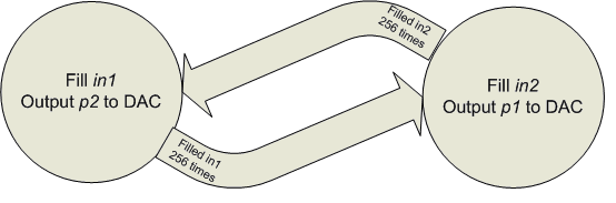
One state machine (figure 5 ) sampled the data at the microphone input to an m4k block and put data into the DAC from another m4k block. At any given point in the program, we were putting samples into one m4k block and outputting from the other. The initial state was that buffer in2 was the input and buffer p1 was the output. After 256 ticks of the audio DAC clock, buffer in1 was input and buffer p2 was the output. This buffer switching was done so that at any point, one output buffer, p1or p2¸ was being filled with time stretched data while the other was being outputted. The reasoning is the same for the input buffers in1 and in2. Once one input buffer was full, this state machine signaled the other state machine that data was ready to be processed via the control signal input_ready.
Figure 5: Input buffer filling state machine
Time stretching the sampled input
Once one of the input buffers was full, the fill state machine signaled the other state machine, which performed the time stretching. The algorithm first determined which output buffer it would need to clear so that new time stretched data could be stored. This was done with two memory state registers called playing and clear_data. For all intents and purposes, these two registers were the same at any time, but we decided to use separate ones to clear and fill the appropriate register for easier readability of the code. These variables kept track of the previous state of the fill state machine. To clear the appropriate m4k block, we iterated through the entire block length of 1024 words and wrote zeros in each location. Once the appropriate block was prepped, the state machine began to time stretch the data.
The user could choose to either increase or decrease the frequency by a factor of 2 or 4. This is selected using switches SW[2:0] on the DE2 board:
Switch Position (SW 2-0) |
Frequency Shift |
000 |
No change |
001 |
2x increase |
010 |
4x increase |
100 |
2x decrease |
101 |
4x decrease |
A 2x increase in frequency meant that the input data would be stretched to twice its normal length. Therefore if the input was 256 words, the output would contain 512 words. A 2x decrease meant that opposite would happen. If the input was 256 words, the output would contain 128 words.
As it turned out, we were unable to fully implement the time stretching algorithm detailed in the “Theory” section. Since that algorithm requires the overlapping blocks to be faded in and out using the cross-correlation, it was computationally too expensive to perform in real time. We were forced to come up with a simpler way to time stretch the signal.
Since we are only transforming blocks that are 256 samples long, we made the assumption that the signal over this time would be periodic (meaning that the pitch doesn’t change much in this short interval). This assumption is mostly correct, especially for a person’s voice.
Time stretching a periodic signal can be achieved by repeating or truncating the signal a certain number of times. For example, to stretch a sine wave by a factor of 2, you only have to repeat the same data to produce a sine wave of double the length with the same frequency. Likewise, to stretch it by a factor of 0.5, you just have to truncate the signal half-way through.
We decided to take this approach to time stretching because it could be performed within the time constraints of our system and produced fairly good results. Our method does produce some discontinuities in the output signal, especially when truncating the signal. This occurs because the signal might not be perfectly periodic within the 256 sample long interval, or truncating it might result in some data being lost. An example of when these problems would occur is shown below.
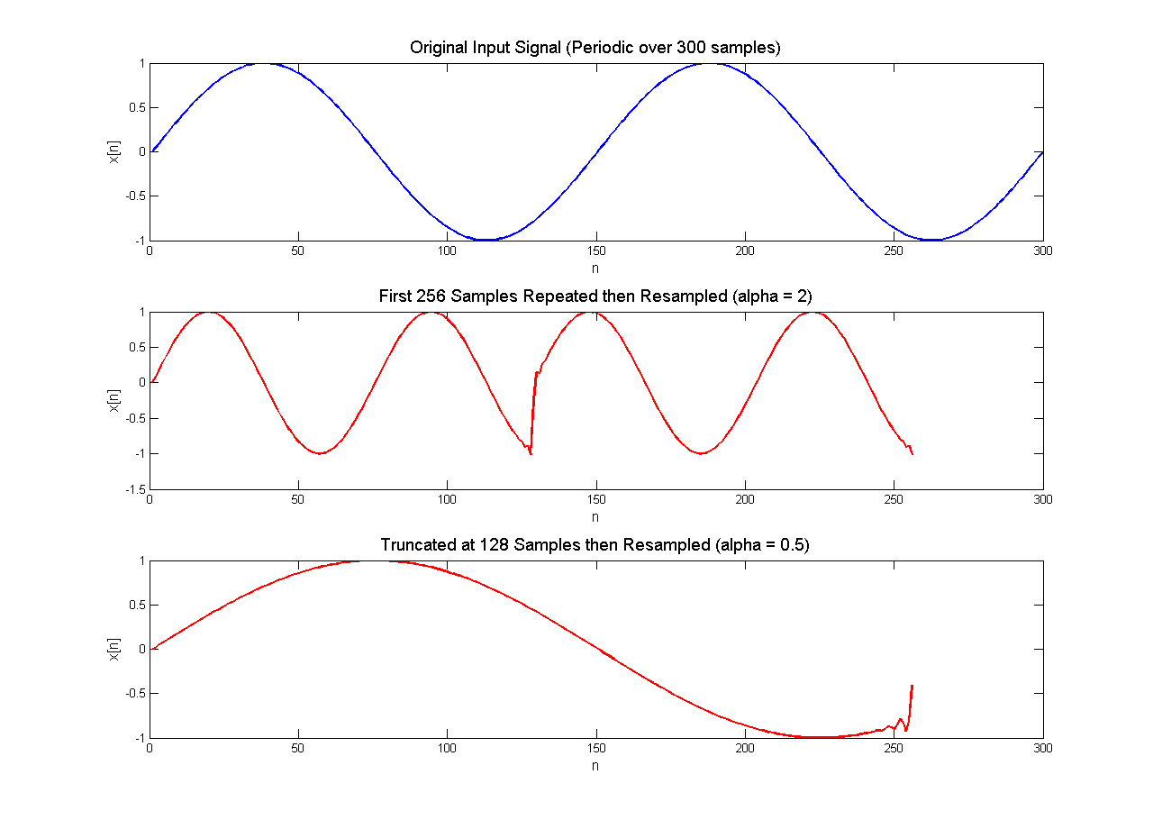
Figure 6: Errors that can occur using our time stretching method
We attempted to remove some of the discontinuities caused by this problem using a three point averaging filter, which did help somewhat. We implemented this method in hardware by setting the transform_length variable appropriately (512 for a = 2, 128 for a = 0.5, etc.) The following diagram illustrates the time stretching (or compressing) state machine.
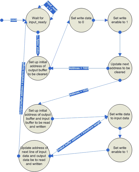
Figure 7: The buffer clearing and time stretching state machine
Playing the time stretched samples
In order to play the time stretched data and obtain our pitch shifted waveform, we resampled the data at a rate relative to the amount of time stretching we performed. This was done in the input buffer filling state machine. Since we could not change the sample rate of the output without changing the sample rate of the input, we instead changed which samples were being played from the output buffer. Normally, if the switches are set so that there is no time-stretching, the output is sampled at the same rate as the input. This is done by having by reading from the same address index in both the input and output buffers. The address was determined by a register called bufferIndex.
However, if the output data was time stretched or compressed, the data would need to be sampled at a higher or lower frequency. This was accomplished by shifting the contents of bufferIndex left or right before putting it into the output buffer address. So if the samples were stretched by a factor of 2x, bufferIndex would be multiplied by a factor of 2, which is a shift by one to the left.
Other Methods Tried
We also tried to accomplish pitch shifting in the frequency domain using the built-in FFT megafunction in Quartus. The approach seemed simple enough and Altera provided documentation on using the FFT block generated by the wizard. In fact, the FFT block supported a variety of input types as well as the ability to do an inverse transform. However, we found that following the simple timing diagram provided in the FFT documentation was not enough. Like many of the complex functions provided by Altera, the documentation was insufficient to create a working piece of hardware in a short amount of time. Perhaps if we had started with this approach rather than tried it halfway through our project, we would have had more success, but that was not the case.