|
Paint Brush Application
|
|
| Introduction
| High Level Design
| Hardware
| Software
| Interface
| Results
| Conclusion
| Appendix
| Downloads
|
|
|
|
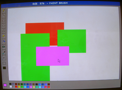
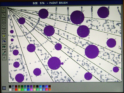
Design Difficulties During the initial face of the project, we had used the VGA component of the SOPC builder to drive the VGA signals to the hardware through the NIOS. It made use of the M4K blocks to store the data. But this implementation was not useful to us since by implementing this only two colors can be used at any point of the time. It can either send a value of 1 or 0 which would either set a pixel or clear it. Because of this drawback, the VGA controller was implemented in hardware and use the SRAM instead of on chip memory. By way of using the SRAM, more than 2 colors can be used. The number of colors that can be used depends on the number bits of data bus available. With 8 bits of data that is used by us, 256 different colors can be used. 28 of these are included in color pallete. Changing our design from soft controlled VGA to a hardware VGA and interfacing it with the USB driver in the software was time consuming. Interfacing the Mouse and the VGA to the DE2 board was the prime task involved in the project. It was a complex task to make the VGA signals get in synchronisation with the USB mouse. After successful interface of VGA to the USB mouse, the implementation was limited to software where all the necessary algorithms are implemented. Two images are shown below.
Statistical Analysis of Paint Brush Application For computing the statistical data and determining the performance of the "Paint Brush Application", various shapes and figures of different sizes were drawn on the VGA monitor through the UBS mouse interface and time was recorded for each of them, so as to determine the efficiency and swiftness of the program execution. The data obtained above is enumerated in the given table (ref. Table1) which has the following three columns: type of figure, size of the figure and the time taken for drawing that particular figure on the VGA monitor. Here, the size of the image is measured in terms of the number of pixels; for circle, the size is dnoted by the diameter in terms of number of pixels and for square, the size is denoted by Width x Height, both in terms of number of pixels on the VGA monitor.The time taken is measured in seconds.
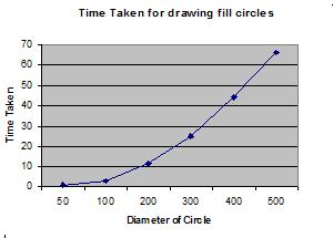
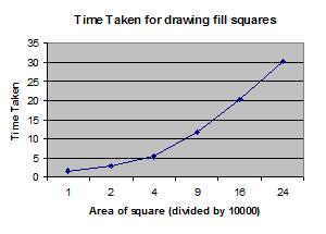
Table 1: Statistical Analysis of the Paint Brush Application The data obtained above in Table1 can be depicted graphically for fill circles and fill squares as shown in the below graphs. The first graph (ref. Graph1) displays the value of diameter of the circle in terms of number of pixels on the x-axis and the time taken to completely draw that circle on the VGA screen on the y-axis. The second graph (ref. Graph2) displays the value of area of the square in terms of number of pixels on the x-axis and the time taken to completely draw that square on the VGA screen on the y-axis.
Graph 1: Time Taken for displaying a Fill Circle
Graph 2: Time Taken for displaying a Fill Square From the above graphs, it can be concluded that the time taken for drawing a figure on the VGA screen increases in direct proportion to its area or size, which is as expected. The time taken for other toolbar options like drawing a point, drawing a line, using the eraser option, spray paint, pick color, etc is negligible, with the figure being displayed on the VGA screen instantaniously, at the click of the mouse. The fill color option, reads each pixel from the VGA and then send new color to the pixel based on the edge fill algorithm. Hence, the time taken for the fill color option depends on read time from VGA and the write time to the SRAM. It also depends on the fencing boundary chosen by the user which determines the scan area. Hardware Usage The Hardware logic for this application was designed and implemented on the Cyclon II family of Altera supported FPGAs. Cyclone II family of devices support the Nios II embedded processor which allows custom-fit embedded processing solutions. They include a powerful FPGA feature set, optimized for low-cost applications including a wide range of density, memory, embedded multiplier, and packaging options. The specific device number, under the Cyclon II family, used here was EP2C35F672C6. The NIOS II CPU employees about 1400-1800 LEs with the remaining 33216 LEs available for the hardware implementation of Paint Brush Application. The specific details of the hardware module are depicted in the below table (ref. Table2):
Table 2: Hardware Usage description and values
|
|
|