Introduction:
We implemented a fully functional music player, capable
of playing music files through the Altera DE2 board. The motivation behind this
project is the impact of the music players in this decade. Features like
portability and ease of use made the music players a grand success among
people.
Our idea is to
create a music player using programmable logic and analyze the various
processes involved in the system. We designed a music player that plays music
files from SD card in real time, while providing user interaction, such as
pause music, fast forward and more. Though the initial idea was to implement a
music player to play (.mp3) files from the memory, we revised the goal to
implement a music player that is capable of playing .wav files (media files).
This was performed due to various constraints involved in the design of an mp3
decoder.
High Level
Design:
SD CARD Controller:
The basic
memory used here is the SD card. The board has a SD card slot, into which the SD
card is inserted. The SD card controller is designed to provide the interaction
with the SD memory. In order to find the best possible method to interface the
SD card with DE2 board, we came across various existing IP cores that could be
used to control the SD card at the HAL abstraction level or by physical
implementation.
The SD card
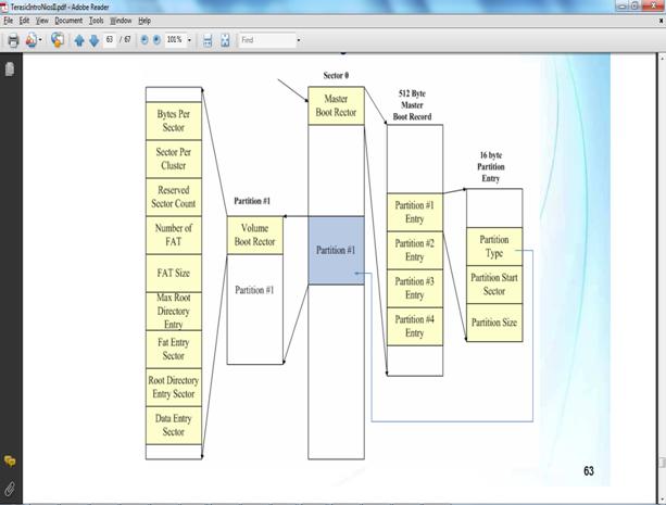
file system needs to comply with the following requirements:
-
FAT 16 file
format, implies that the smallest data element is 16 bits long.
-
Also, the FAT 16
format partitions the whole memory into blocks of data, each block consisting
of 512 bytes.
FAT 16 file system:
The FAT 16
system is required by the SD card Controller to detect the card. This system
partitions the whole memory into blocks, where the partitions are performed as
given in the diagram below,
SPI interface:
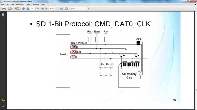
We chose to
implement the SD card based on SPI mode of communication. In SPI, one bit data
transfer is obtained. This allows the design of the interface to be simple and
easy. But, it has lesser performance when compared to the SD card bus mode,
where parallel data transfer is possible (upto 4 bits). In SPI, the pins used
are SD_CLK, SD_DA and SD_CMD. The SD_CLK is used to set and maintain the Clock
speed of the SD card, upon which the other pins communicate with the SD card.
The SD_CMD pin is basically used to send the commands, CMDxx and ACMDxx being
the command representations. Here, CMD refers to general SD card commands, ACMD
referring to specific commands and xx stands for the number of a particular
command.
SD
card controller - SPI mode
Further, each
command is transmitted as a frame, of size 6 bytes. Each frame starts with a
‘01’ signal followed by 6 bits of command numbers. Then, 4 bytes of the command
argument is sent. Finally, the last byte containing 7 bits of CRC and the stop
bit is transmitted. Now, the SD card waits for the response from the SD card,
and the possible responses varying with individual commands.
SD card Command structure
SD_card_init(void):
This function is used to detect and initialize the SD card. The CMD0 is
sent by this function to the SD card and the response I awaited. The response can
be only of certain types, such as CRC error, idle etc. Based on the response
this function returns a value. In case there is no response from the SD card,
it returns a value ‘1’. When the card is detected and initialized, it returns a
zero value.
SD_read_block(UINT32
block_number, BYTE *buff) :
This function is used to read a single block of
memory in the SD card. By understanding the timing information given below, we
can use the read function to read 512 bytes of data.

SD card read
operation
SD_read_lba(BYTE
*buff,UINT32 lba,UINT32 seccnt) :
This function is used to read multiple blocks from
the SD card. First, the CMD17 is sent across to the SD card, which represents
the Read command. Next, the data line is monitored for current data transmissions.
Then, the function reads byte by byte from the SD card location specified by
the ‘lba’ value. After the 512 bytes have been read from the block, it repeats
the function for the given number of sectors.
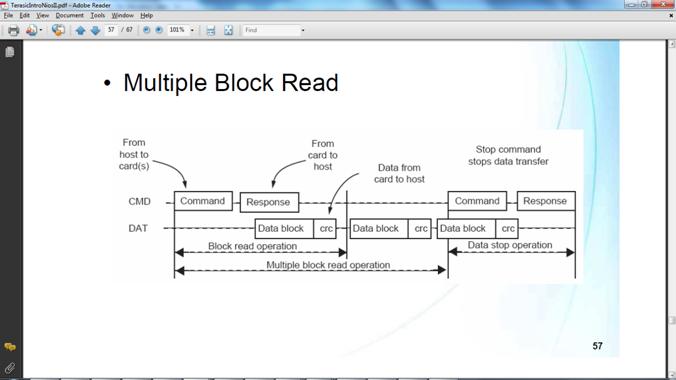
Multiple
block read
send_cmd(BYTE *in) :
It is the
basic function of the SD card controller. It uses the SPI interface to send and
receive information. It is used by other functions to send their commands.
response_R(BYTE s) :
This function waits for response from the SD card
and reports it other functions. Hence, it used as a basic function by other
high level abstractions.
AUDIO CODEC:
We require
the digital data from the SD card to be given to the analog LINE OUT of the board
to get the music. This part of the system is the Audio Codec. The various
modules required to carry out this function are:
-
The FIFO module:
This is a 256 * 16 bits wide buffer used to bridge the NIOS and the DAC. The
data from the NIOS is given to this buffer to serialize the data stream.
-
I2C interface
unit, which controls the flow of data in the codec.
-
PPL module,
generating a clock frequency of 18.4MHz.
The audio
codec generates the AUD_LRCLK in synchronization with the 18.4MHZ clock
produced by the audio_pll. At the positive edge of this LRCLK, the data is
being latched onto the oAUD_DATA variable, which is then transmitted to the DAC
portion in the board. The .wav file is sampled at 48Khz, so the DAC sampling
frequency is also set to 48Khz. The deemphasis is set to 48Khz too.
SOPC Builder:
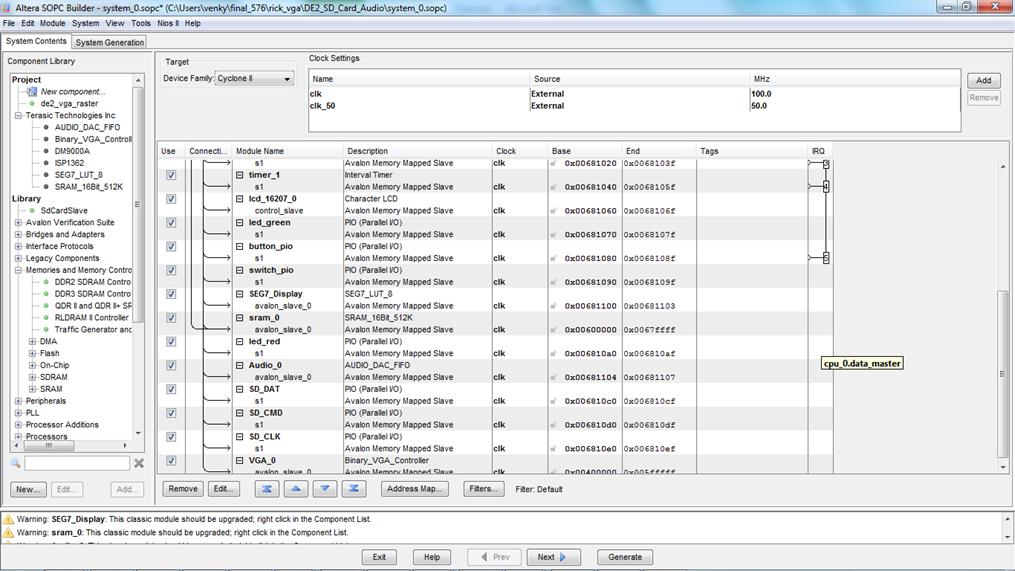
SOPC builder screenshot
The SOPC
builder is used to connect the major components of this project, including the
Audio Codec, the SD card interface and other peripherals. These components have
base addresses assigned to them, by which read and write operations can be
performed.
The
SMD_CLK,SMD_DAT,SMD_CMD are the PIO used to communicate with the DE2 board via
the SOPC builder. Similarly, the Audio codec has been instantiated and the 16
bit data from the NIOS II gets written directly into the audio codec. All these
modules operate at 100MHz frequency except for the SD RAM Controller. The SD
RAM controller provides the memory for the NIOS II processor.
NIOS II:
Basically,
this project has a large chunk of functions being implemented on the NIOS II
processor. This can be seen from the fact that using a HAL level makes it very
easy to use the SD card. Naturally, the music player operation and user
interface is built using the NIOS II. Here, the main() function contains the
music player. Here, the various SD card functions are called to perform the
tasks.
Flow of NIOS code
Basically,
the NIOS II top level function controls the operation of the player. Once, the player
is started, NIOS processor waits for the SD card to be inserted into the slot.
Once the SD card is inserted, the initialization takes place. Here, the file
system is detected and the file directories are listed. The
file_list(<arguments>) function is used to find all the media and lyric
files present in the SD card. This is done by searching through the FAT16 file
directory for the file types: .WAV and .LRC. This data is displayed by the LCD
and the user is allowed to select the song. Also, the user can choose to play
all the songs in from start to end by selecting the SW[0] switch.
The KEY[2]
and KEY[3] are used to browse through the playlist to select a particular song.
This is made possible by displaying the name of the current song. Once the user
browses through the directory and decided to choose a particular song, KEY[1]
should be pressed twice to select the song, indicated in the LDC screen. Once a
song is selected, it is read from the SD card and sent to the FIFO buffer. The
‘song_position’ value determines the byte address within a song, while
‘song_num’ determines the list of songs. The Switches SW[4], SW[5] and SW[6]
are used to fast- forward, go reverse and pause the song respectively. Also,
SW[3] selects the random mode, by which the player outputs songs based on
various random factors: the current song data combined with the total number of
songs and total number of files, finally a modulo division by the number of
songs. Once a song is played completely, the player returns to the main menu.
The SW[17] is used to manually reset the player, to make it go to the initial
stage.
Now, the
current byte address of the song is determined, and the SD_read_lba() function
is used to read from the SD card, in order of 512. This 512 bytes value is stored
in the buffer named temporary1. Next, the buffer data is transmitted to the
Audio_DAC_FIFO. Also, we designed an equalizer, using the LED’s, which displays
the power of the sigan(sound), as time progresses.
VGA
Controller:
The VGA controller was implemented using the SOPC builder. The VGA
controller was used to display a picture when the music player was started. The
BMP image was decoded by the VGA controller once the player started and this
command was sent from the NIOS to the VGA controller.
Peripherals:
LCD Controller:
This is the
16*2 character LCD IP core is instantiated in the SOPC builder. It is connected
to the top level module of the system, while it is accessed by the NIOS by
writing into the base address. It can display upto two lines, ASCII characters.
It used in this project to display the status of the music player and the
Lyrics at real time.
Seven Segment display Controller:
This module
is also instantiated in the SOPC builder, and it is used mainly to display the
time with respect to the song being played. Also, it displays the song number,
and the total number of songs available in the memory.
PIO:
Various PIO’s
are used to transmit data between the NIOS and the hardware module. The PIO’s
are used to get the input from the switches and keys. The
Testing:
This project was developed in various
stages. Our initial
idea was to implement the SD card IP core (provided by the Altera University
Program IP cores). We could implement the IP core on the SOPC builder but the
NIOS program on the HAL platform failed to provide the required results. We
were unable to detect the file system of the SD card using this IP core. Hence,
we implemented the SD card controller using the SPI interface.
We started on a basic project example provided
by Altera/Terasic for DE1 board. This example had audio codec and many other
components. But, most of these components such as ISP interface, EPCS
controller etc. were not required for this project. Also, this project uses an
earlier version of Quartus and SOPC builder. Hence, most of these components
could not be upgraded to the SOPC builder that we used. Hence, we just used the
SD card SPI interface provided by this example. Thus, we could upgrade the SOPC
builder to the current version. By the end of this phase, we designed the
components. The Audio codec (Wolfson WM8731) and the VGA controller are the
major parts of the SOPC builder.
We started designing the functionality of
the player, in NIOS. We tried to read the .wav files initially and send it to
the audio codec. We used Slave addressing to transmit the data from NIOS to the
audio codec. Similarly, we used the slave addressing to all the peripherals
too. We had to understand how to use these addressing modes, to implement them
in the NIOS. Then, we designed the function to read the lyrics file. Once this
is completed, we began to design the user interface. We implemented the basic
functions: Pause, fast-forward, reverse. Next, we implemented the random play,
continuous play and the repeat mode. Finally, using the timestamp function, we
designed the synchronization between the lyrics and the music.
The final phase consisted of testing the
quality of output. The output from the DAC seemed to be distorted from the
actual data from the SD card. The quality of the music hence was degraded. We
tried to resolve this issue using various debugging methods. We analyzed the
output from the DAC channels with the oscilloscope, finding an interesting
pattern. We gave a 1000Hz sine wave input from th SD card and observed the
output from the LINE_OUT. We found that after certain intervals, the sine wave
output was deformed for a very short period. The deformation could be seen as a
sharp peak or a flat level output etc. We tested the system with different signals.
We passed a 1000KHz sine wave one-channel input. We observed that the output
from the DAC was from both channels. Also, the frequency at the output deviated
from 1000 KHz. We performed tests by varying the clock input to NIOS and the
audio codec. The sampling rates were also modified to 44.1KHz and tested.
Result and Analysis:
The music player was successfully
implemented, in real time. The user interface consisted of:
Display:
The VGA display, LCD display, seven segment
and LED’s were used for showing various functions of the player. The VGA
controller was used to display an image when the music player was started.
Then, the LCD display showed the playlist and displays the input that the
player requires from the user (Ex. Press KEY[1] to select a song). The seven
segment display gives the current play time of the song, the current song
number being played and total number of songs. The LED’s were used to display
the equalizer.
Control:
The user controls the music player through
various controls such as the song selection (next, previous), play mode
(random, continuous, repeat). Also, the user can control the song, while it is
being played, pause, fast forward and reverse. Overall, our wav player gives
the user almost all the functions that an actual music/mp3 player can have.
Quality:
The music player was limited by its quality
of output from the DAC. This turned out to be having some distortion. It is
seen that music involving a range of sounds, with high frequencies could not be
played as well as the music involving minimal range of sounds. This could be
due to various reasons. First, it might have been due to out of order byte
transmissions, so that some parts of the music were distorted. Also, this could
be an issue with the SD card access speed. The FIFO buffer could have been
emptied by the DAC, before the NIOS could refill it. Also, the NIOS running at
100Mhz could be an issue, since the audio codec is running at 18.4 MHz.
Conclusion:
The wav player was designed with interesting
features and gave good output. WAV player was an interesting project to
implement, and the NIOS and IP cores were important areas that we could
explore. We have a good idea of how to use the SOPC builser, the NIOS and the
IP cores. Having the freedom to choose our final project gave us a lot of
choices and ideas to come up with.
Since, the whole system involved Avalon bus, we understood the
addressing methods with the Avalon slave and master. By the end of this course,
we gained considerable knowledge in FPGA’a , digital design, verilog coding and
debugging skills.
IP core Considerations:
We have uitlized terasic/Altera Audio codec, VGA controller
and the base project of SD Card reader.
Acknowledgements:
We would like to thank altera/terasic technologies
for providing the basic SD card reader project on which we could work. Also,
our sincere thanks to Bruce Land for his help throughout the course, and for
providing such an unique and effective course, in terms of gaining practical
knowledge.
Appendix:
Work Breakdown:
|
Top module
IP cores |
Both |
|
VGA
controller |
Rick |
|
Audio codec |
Venkatesh |
|
User
interface in NIOS |
Both |
|
Debugging |
Both |
Code:
References:
2- http://www.terasic.com.tw/cgi-bin/page/archive.pl?Language=English&CategoryNo=56&No=372&PartNo=4
3- terasic Introduction to NIOS demo (pdf).
5. http://www.cs.columbia.edu/~sedwards/classes/2010/4840/index.html