Connect Four AI
Megan Backus (mb2532), Andrew Tsai (aht53), Rohan Agarwal (ra462)
12/21/2021
Megan Backus (mb2532), Andrew Tsai (aht53), Rohan Agarwal (ra462)
12/21/2021
For our ECE 5760: Advanced Microcontrollers final project, we decided to create a Connect Four AI in hardware on the FPGA. The goal was not only to develop an AI with a certain degree of challenge for a human player, but also to accelerate the program to perform and make decisions much faster than a software-based AI with the same behavior would be able to. Our end result is a virtual Connect Four player that makes decisions strikingly similar to how a human player would approach the game, due to our intuition-based development of the multiple logic layers that our final AI consists of.
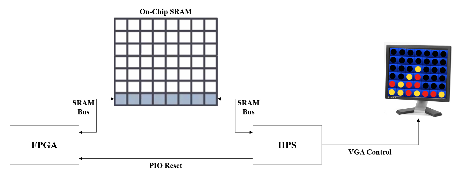
The high level structure of our design is shown in the diagram above. When first running the HPS program, the HPS initializes an empty game board, draws it on the screen, and prompts the player to either make a move or let the AI go first.
Afterwards, the HPS resets the FPGA and then sends the game state data to the FPGA through the SRAM bus, on which resides the AI and associated logic. The AI determines a move, sends it back through the SRAM bus, and the HPS updates the display to reflect the AI move and prompts the user for the next move.
We approached our AI design with a focus on how a human player intuitively analyzes game states and makes gameplay decisions. Although there are existing algorithms capable of always making the most optimal move, we chose not to go in that direction due to the excessive usage of memory and recursive functions for the sake of traversing an exponentially increasing number of game states, which is in practice very difficult to implement in hardware. Instead we opted for an iterative design approach, starting with the most basic defensive behavior and adding a variety of defensive and offensive behaviors based on a custom heuristic we designed which closely follows human intuition when playing the game. This allowed us to create a reasonably challenging AI that implements move anticipation using purely combinational logic such that the move determination could be completed within a single clock cycle. This is also described in greater detail within the “AI Design Iterations” section.
The Connect Four game infrastructure is implemented in C and runs on the HPS while the AI logic is implemented in hardware on the FPGA. The current game state is communicated between the HPS and the FPGA via shared SRAM memory.
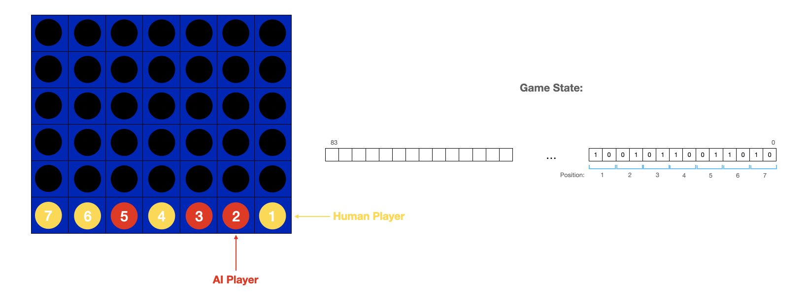
The game infrastructure utilizes an 84-bit value to represent the current state of the game. Each position of the 6 x 7 Connect Four board is represented by two bits of information, with 00 = empty position, 01= AI token, and 10= human player token. This 84 bit value is segmented into 6 14-bit rows that are individually stored at a distinct memory address in shared SRAM memory. The FPGA then has to perform six sequential SRAM reads in order to obtain the full game state written by the HPS. The structure of the 84-bit game state value and how it maps to the Connect Four board is shown in the diagram below.
On the FPGA side, the Connect Four AI implementation utilizes a top level finite state machine to read the current game state from SRAM, compute the next AI move, and write the new move to SRAM. The top level FSM is depicted in the diagram below.
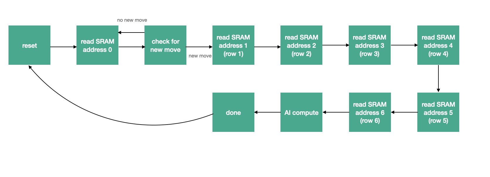
The FSM first reads the value at SRAM address 0, which serves as a flag to communicate between the FPGA and HPS when a new human player move is available. If there is a new move, the FSM progresses to read the next six memory locations, otherwise it returns to the initial state. SRAM address locations 1-6 contain the 14-bit game states of each of the six Connect Four board rows. Once the full game state has been read from SRAM memory, it is fed into the AI compute module, which determines the next AI move in a single cycle. There are two AI compute modules that are utilized throughout the game. During the first four rounds of moves, a simpler and purely defensive AI module is utilized when the board is relatively empty, which evaluates the next move based only on our defensive heuristic. After this, our full AI compute module (described in detail later) is used to determine the next AI move. This new AI move is then written to SRAM memory at address 7, and the HPS is signaled that a new AI move is available.
The hardware implementation of the AI compute module is shown in the block diagram below.
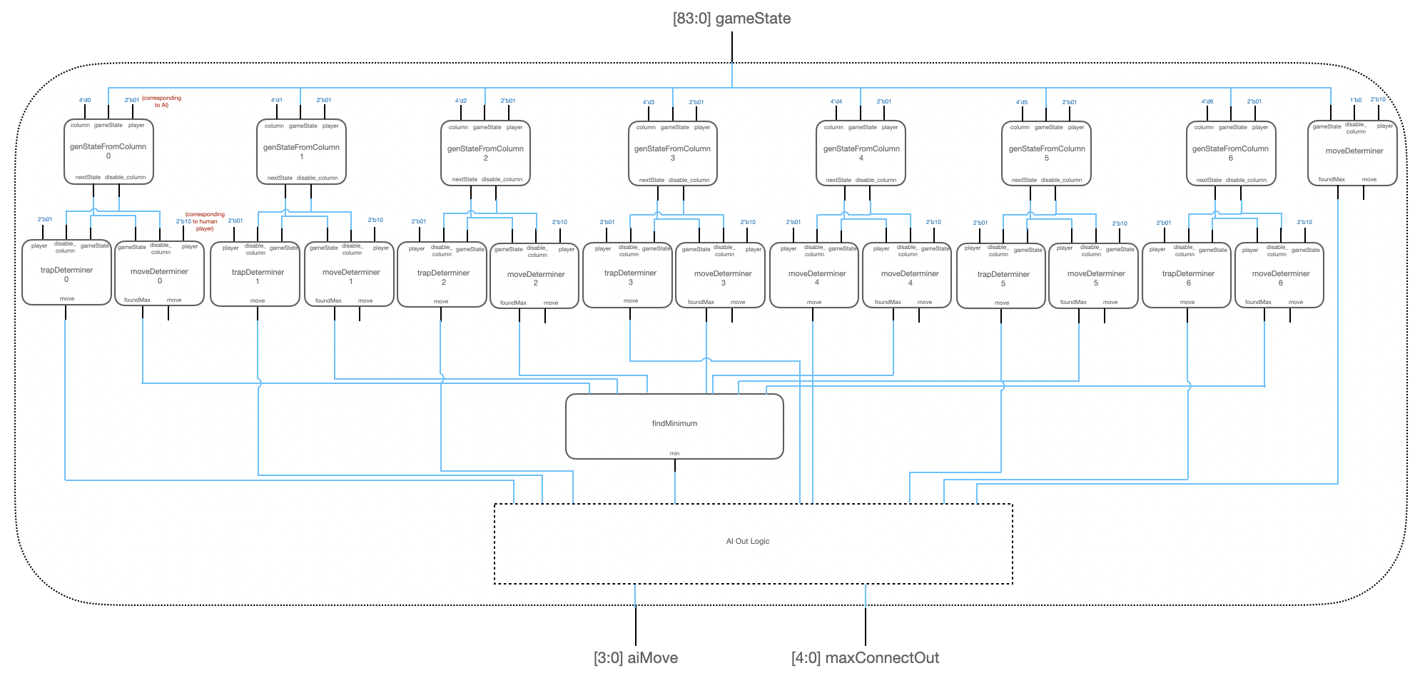
The top level AI module is implemented entirely in combinatorial logic. It first utilizes seven genStateFrom Column modules to produce an 84-bit game state for each of the possible next AI moves. It then utilizes a trap determiner module and a move determiner module per newly generated game state. These modules produce predicted moves based on a predicted game state one move ahead of the current game state. In parallel, the AI move also utilizes another moveDeterminer module using the current game state to make two priority checks: 1) if the AI can win in the next move and 2) if the AI must block the human player from winning in the next move. The AI out logic prioritizes these checks as determined by the rightmost moveDeterminer module in the diagram before considering the parallel moveDeterminer and trapDeterminer logic outputs. The outputs of the trap determiner module are fed directly into the AI out logic. The move determiner modules output a maximum heuristic value for a particular human player move given the generated game state. These seven maximum values are fed into a findMinimum module that outputs the minimum of these heuristic values. This value is then used in the AI out logic to determine the final AI move.
Each moveDeterminer module utilizes seven maxConnectFinder modules, as shown in the block diagram below. The maxConnectFinder modules receive as inputs the rows of the generated game state and use the same heuristic to produce a value corresponding to each of the seven possible moves. It outputs the maximum of these values. Each of these correspond to the move that the AI determines is the most likely for the human player to play given each of the possible game states. The moveDeterminer module utilizes the minimum of these maxConnectFinder outputs to produce the best AI move, predicting the human player’s next move.
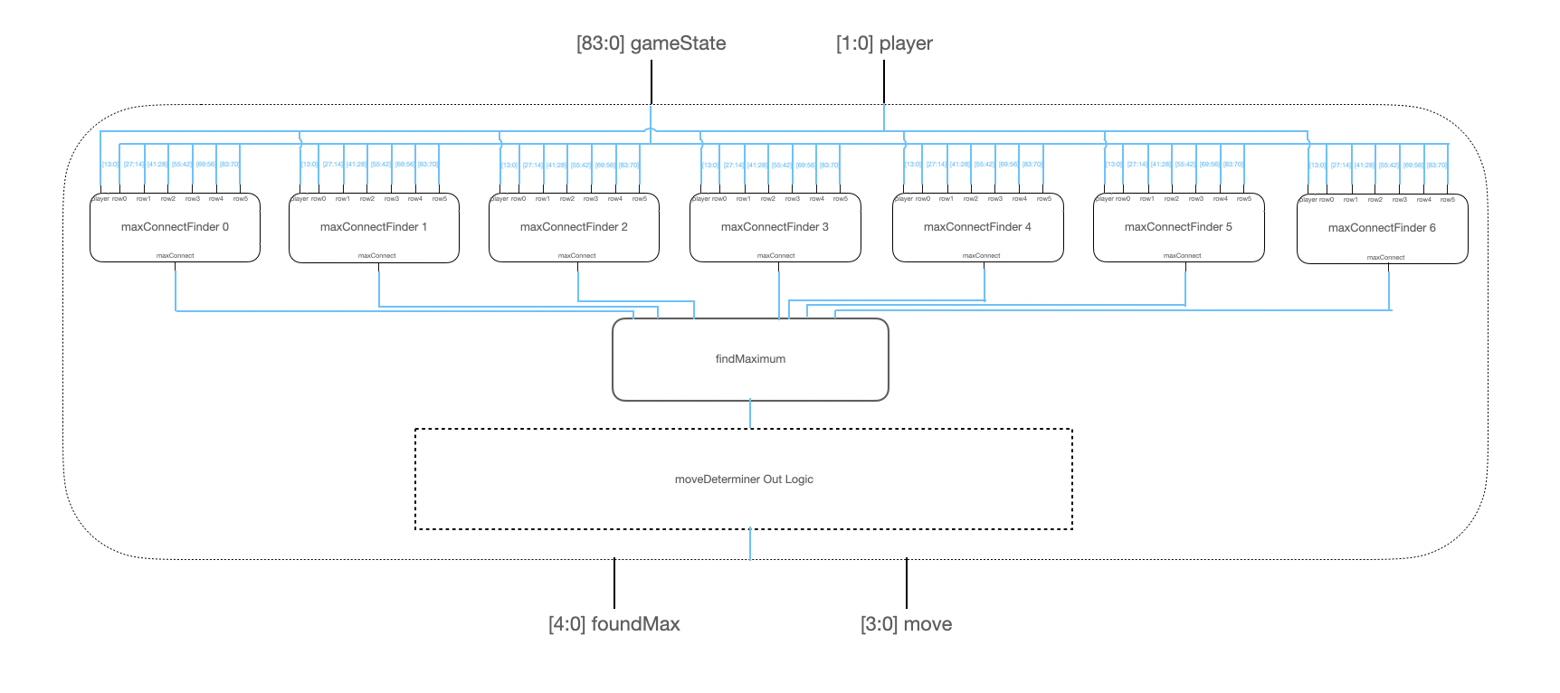
The maxConnectFinder module utilizes the following logic to compute a heuristic value for a given move column and game state. It first checks to see if playing in this column given the input game state will produce an AI win. If so, it assigns this move the highest possible value. It then checks to see if a move in this column is necessary to block a human player win on the next move; if so, it assigns this move the next highest value. It then assigns the column a value equal to the weighted sum of the number of consecutive opponent tokens bordering the next open position in that column. So, it assigns a position next to a string of two opponent tokens a higher value than a position next to just one opponent token. It also takes into account open spaces between player tokens, i.e. it assigns a position that has an opponent token on either side the same weighted value as a position next to two consecutive opponent tokens because placing an opponent token in that position would result in a string of three opponent tokens in both cases. This same maxConnect logic is used both in determining AI moves and in the reverse case, predicting human player moves for looking ahead.
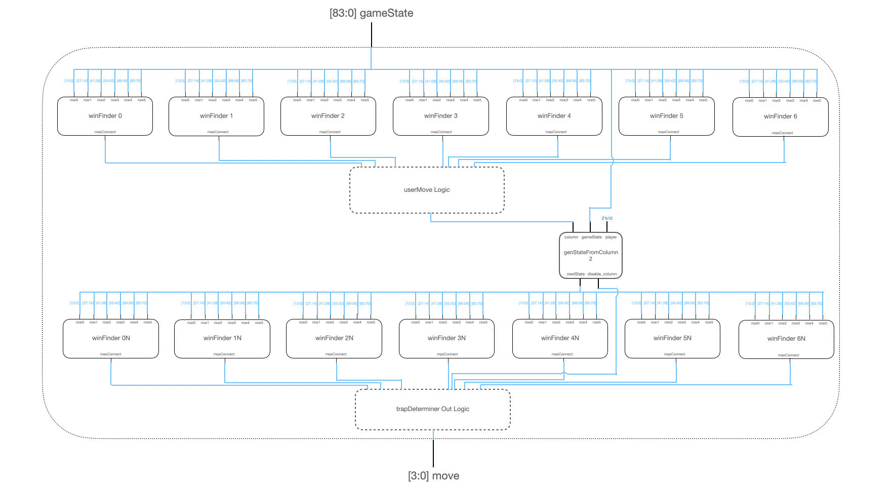
There are seven trapDeterminer modules in parallel with the seven moveDeterminer modules. Each trapDeterminer module also takes in the newly generated gameState. The trapDeterminer module first utilizes seven winFinder modules to determine if any of the moves given the input gameState can generate an AI win, which the human player would most likely block in its next move. If so, it generates a new gameState using a genStateFromColumn module with a human player token in that blocking position and subsequently uses seven more winFinder modules to determine if an AI win is possible.
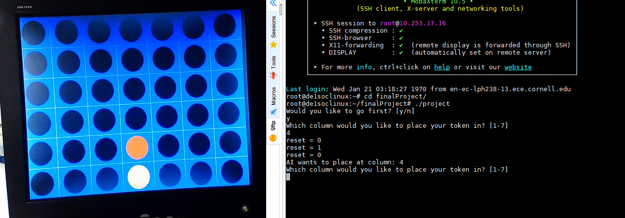
Regarding the software design itself that is running on the HPS, as aforementioned, the main goal of the C code is to act as an intermediary between the FPGA (which is actually computing the AI’s next move) and the VGA display of the Connect Four board. Additionally, due to the remote nature of this semester due to the COVID-19 pandemic, we also needed to utilize the C code to serve as the user’s interface for inputting their moves into the game.
The C code begins by including all relevant libraries and setting up the shared memory-mapped addresses between the FPGA and the HPS (for example, for the VGA interface, the shares PIO port for HPS-driven reset to the FPGA, and the base address for the shared on-chip SRAM used to communicate between the HPS and the FPGA). It then toggles the reset on the FPGA. Once this initialization, as well as other variable initialization, has been complete, the C code draws an empty Connect Four board on the VGA by means of drawing perpendicular vertical and horizontal lines to create a 6x7 grid, and by placing discs in each created square. The game then prompts if the user would like to go first or not, and lets the user type into a terminal the column it would like to place its move in. There is some basic error checking to ensure that the entered column is valid and can actually have a token placed inside of it, and this error checking code will constantly press the user for a valid move until one is inputted (via use of a do...while() loop). Once these error checks are satisfied, the C code will call a helper function called placeDisc() that will take the user’s inputted move, a variable tracker that keeps track of what row to place a token in for that particular column, and the player that inputted the move (AI or user). The placeDisc() function then overwrites the corresponding disc on the VGA display with the appropriate color, updating the player’s move in real time.
After the user’s move has been played, it is necessary to update our game state representation (recall this was the 14-bit representation of each row of the board that indicated which tokens were placed where). To do so, we used an updateGameState() helper function, which took as an input an array used to track the game state rows, the row we would be placing our token on, the corresponding column of that placement, and which player made that move. The function then does binary-based arithmetic, an optimization that was necessary due to the nature of the data we would be sending to the FPGA for processing. To update the game state row, it is important to note that we are effectively adding a power of 2 to the current game state representation. As such, the code determines the exponent of the power of 2 we are adding (by using the column_to_place as well as the player), and then raises 2 to the power of that exponent and adds that to the original game state row.
After all our trackers have been updated to reflect the player’s move, this data (all row game states) is sent over to the FPGA via the shared on-chip SRAM. The C code then indicates there is new data available to the FPGA, which will then read the data, perform its computation, and then write to a new location on the SRAM the move that the AI would like to make. The C code would then perform the same process it did for the player’s move (displaying the appropriate disc, updating the game state, etc.) before repeating the process. Note that our game framework has the inherent assumption that the AI will not return an invalid move to the HPS. Also note that all updating of the game states, even on the AI side, is done by the HPS to make the interface easier and require latency from on-chip SRAM accesses.
One of the last portions of the C code to be discussed is the logic implemented in order to determine whether the game has ended. This function, called checkGameOver(), is performed every time someone plays a move (player or AI), and returns 0 if the game is not over, 1 if the game is over and the player who just played has won, or 2 if the game is over and it is a tie. To do all of these checks, the C code must again do binary arithmetic to check for certain cases. As such, based on the player who has just played, the checkGameOver() function will check for certain patterns (i.e. 10101010 in a row, which is the decimal 170, to determine if the AI won) in order to determine whether someone has won or not. Other patterns to check involve checking 4 in a column (which was done via shifting the values in game state rows for 4 rows by the same amount and checking all 4 entries), checking 4 in a diagonal going from lower left to upper right (which was done by checking 4 different game state rows with shift values, aka columns, varying by 1 per row), and checking 4 in a diagonal going from upper left to lower right (which was done by a similar process). Should none of these checks have worked, we check whether the board is full to determine whether a tie has occurred. Else, the game is still ongoing.
If a game over condition has been detected, the program will output a corresponding message to the user’s terminal. It then prompts the user on whether they wish to play again or not, which they can also input via terminal. This play again functionality was possible by putting our entire code inside a do...while() loop and appropriately spreading out our initialization functions so that we can start a fresh game (with a new empty board VGA display and all our internal game state trackers reset). All of this functionality put together enabled a nice gameplay experience that allows a user to truly train their Connect Four skills against an AI that makes decisions comparable to one that an above average Connect Four player would.
When we first researched existing implementations of Connect Four AI’s, a common trend we found was the use of a Minimax algorithm for deciding moves due to the zero-sum-game nature of Connect Four. That is combined with recursively traversing game state trees in order for a properly-programmed AI to always make the optimal move. Our first approach was to try and figure out how we could implement this in hardware on the FPGA, but the immediate roadblock we faced was how we would be able to keep track of exponentially increasing game trees. Consider an empty playing board; there are seven possible first moves, and thus 7 “root” game tree nodes. From each node, there are 7 more potential moves, and so with each iteration of the game the size of the tree increases exponentially. Although still theoretically possible with very careful memory management and re-usage of hardware modules within a complicated outer FSM, we instead decided on a more iterative design approach. We wanted to first implement the overall framework of the game, and then implement more of the AI behavior as we progressed rather than trying to implement recursion and Minimax from the get-go.
After the framework was implemented, our first behavioral model was a fully-defensive AI (first generation) that would, on its turn, strictly evaluate the current game state and play in the spot where the human player would have the highest “profit” (heuristic value) if the human player were to place there instead. We evaluate profit as shown in the following code snippet:

Where given a rowArray representing the current game state along with a moveColumn and moveRow dictating exactly where the piece is to be placed, a profit value is assigned for a specific direction based on the number of consecutive player pieces such that longer connections result in higher profits. These values are calculated for the top left, top right, left, right, bottom left, bottom right, and bottom directions, and summed up to give an overall profit value. This summation occurs within the maxConnectFinder module, and seven of these modules are instantiated in the moveDeterminer module, one corresponding to each column of the game board. The profit values for all seven are calculated, the maximum profit is found, and the column holding that maximum is chosen as the move. In a tiebreaker scenario, priority is given to the middle column, then alternating left and right going towards the outer edges of the board since moves placed closer to the middle tend to have higher potential for connections.
The behavior of this basic AI was rather limited. As it was using a completely defensive heuristic, it would successfully make moves that blocked long connections and would prevent the human player from easily connecting four in a row. However, the AI itself had no concept of aggression, and was also highly susceptible to being trapped due to the lack of knowledge of game states resulting from its current move. This would also lead to scenarios wherein the AI would place a move that enabled the human player to win on the immediate next turn. Of these issues, the main modification we made to this iteration of the AI was checking not only the opponent’s profit, but also the AI’s own profit to see if it could immediately win. In the case that it could make a move that connected four of its own, it would do so in order to win the game. However, against any competent human player this modification made little to no difference in the overall difficulty of the AI. This initial AI, along with the subsequent iterations, was implemented in our final design due to the value that it provided for accurately detecting if the AI needed to make an immediate move to either (A) prevent itself from losing, or (B) win by connecting four immediately.
The next iteration of the AI behavior incorporates looking ahead one move to observe the opponent’s maximum profit given the AI making a move in a certain column on the previous turn (second generation). This would change the AI behavior to prevent it from making a move that would cause it to lose on the next turn (unless forced to), and would also give us an opportunity to implement a pseudo-minimax algorithm. By finding the opponent’s maximum profit given a certain AI move, the AI could then choose to make the move that minimized the opponent’s maximum profit. This comes with the added benefit of being able to use the same maxConnectFinder module without needing to change its functionality. In order to implement this, we needed to first generate seven new game states corresponding to the AI making a move within each column; this was done with the genStateFromColumn module which takes the current game state, player, and a column as an input, and returns the new game state with the designated player having made a move in that column. By instantiating seven of these, all possible game states after the AI move could be generated; these are then fed into seven moveDeterminer modules (resulting in 49 possible move determinations). Within each of these modules, the opponent’s highest potential profit is found for the given AI move, and then the minimum of these values is chosen in order for the AI to make a move allowing the human player the least possible profit. After implementing this, we found that the AI no longer made moves that caused it to lose on the next turn. This significantly raised the playing level of the AI, since it was now much more common to play the AI to a tie if the human player did not set any traps. Furthermore, by choosing the move that limited the human player’s maximum profit, the AI’s overall move choice was significantly improved in terms of difficulty for the human player. The weaknesses of this design, as we observed, were still that it was unable to detect human player traps (since it could not look far enough ahead) and also that it would often find itself in winning trap configurations, but because it did not recognize them, would give the human player opportunities to block it. However, the logic for this AI is the dominant behavior in our final implementation since we deemed it rather sufficient in terms of gameplay difficulty.
The last iteration of AI behavior modifications (third generation) was to allow the AI to detect its own trap setups. To do this, after taking the possible game state outputs of the genStateFromColumn modules, the AI checks whether it currently has a winning configuration, i.e. the human player is forced to block it on the next turn. This is done with a new winFinder module, which has similar functionality to maxConnectFinder, but only returns whether an AI winning move is detected. Based on the move the human player is forced to play, another genStateFromColumn module is used to create that game state, and another layer of winFinder modules is used to check if the AI can win on the next move. This effectively looks ahead in time by two moves, but only identifies if the AI can obtain a winning trap configuration. A major reason we implemented this is to add another element of aggression to an otherwise almost purely defensive AI.
The reason we chose not to implement detection of human player traps is simply because it would require analyzing three moves ahead of the current game state: given AI move, analyze human move, then analyze next AI move, then analyze subsequent human move. In order to effectively implement this, an extra iteration would require 49 * 7 profit evaluation and determination modules, which we felt would push our hardware utilization beyond the limits of the FPGA given the fact that our current implementation (with all three AI iterations effectively in parallel) already used 54% of the ALM’s on the board, and thus would likely not be able to fit an additional level due to the exponential size increase.
Thus our final AI implementation incorporates all three iterations as follows:

foundMax[7] takes the maximum value found in the moveDeterminer module associated with the first-generation AI as a check to see if there are any moves it must make immediately to win or prevent itself from losing. AllFull is a check in case there is only one valid move left on the board. In the case where either of these is true, then the move associated with this module is chosen. Otherwise, the next prioritization step is whether a trap for the AI exists, implemented in the third generation; if it exists and the subsequent player move would not result in a human player win (foundMax[trapMoveFlag] check), then the move that would lead to a trap is played. Otherwise, the default case is to go with the move that minimizes the human player’s maximum profit, established in the second generation.
There were three main fronts upon which we evaluated our design: (1) speed of execution, (2) gameplay awareness, and (3) correctness.
To begin, it is important to note that our entire AI computation was designed to take place combinatorially in a single clock cycle. Since the FPGA our AI is running on it utilizing a 50 MHz internal clock, this means that an entire calculation of the AI’s move takes 1/(50e6) or 20 nanoseconds to complete. This is extremely quick, and thus required us to carefully think about how to parallelize what computation could occur simultaneously in order to fit all the logic computation in a single clock cycle (when done sub-optimally for example, Quartus would return our compilation with timing violations, indicating we needed to go back to our design and reevaluate the structure of it).
Regarding speed, it should also be noted that the FPGA needs to read the updated game state information sent from the HPS via the shared on-chip SRAM. Since our implementation of a standard Connect Four board has 6 rows, this required 6 SRAM reads before computation could be performed, with each read requiring 3 clock cycles (or 60 ns) each. Nevertheless, the fact that the overall core AI can be run at 20 ns is a testament to the parallel nature of the computation-intensive design, which is key in standard accelerator architecture designs (where computation is typically serially offloaded to an accelerator and the host processor waits for a result).
The second, and arguably the most important, evaluation criteria for our design was gameplay awareness. In other words, we wished for this AI to simulate an above-average Connect Four player as closely as possible. This required the AI to be cognizant of various different scenarios that could occur in the game, and react accordingly. We will illustrate several examples of this below.
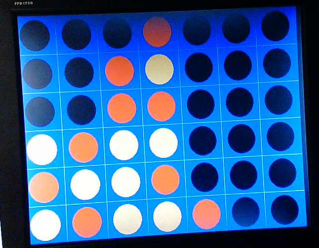
Consider the image below.
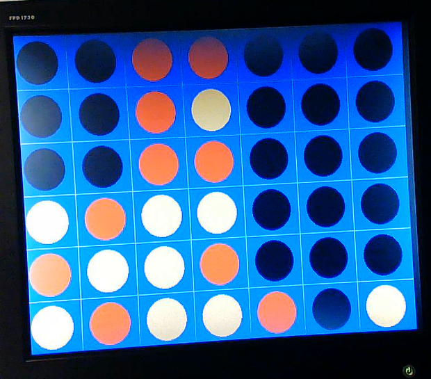
In the above image, we see that if the human player messes up and places their token in column 3, the AI will be able to win on its next turn. When its next turn comes around, we want the AI to take advantage of this and claim the win. In the below image, we see that this is indeed the case, and that the AI wins.
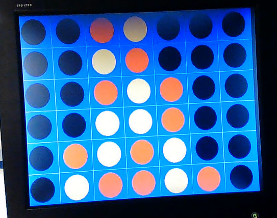
Another common case we wanted the AI to handle can be seen below.
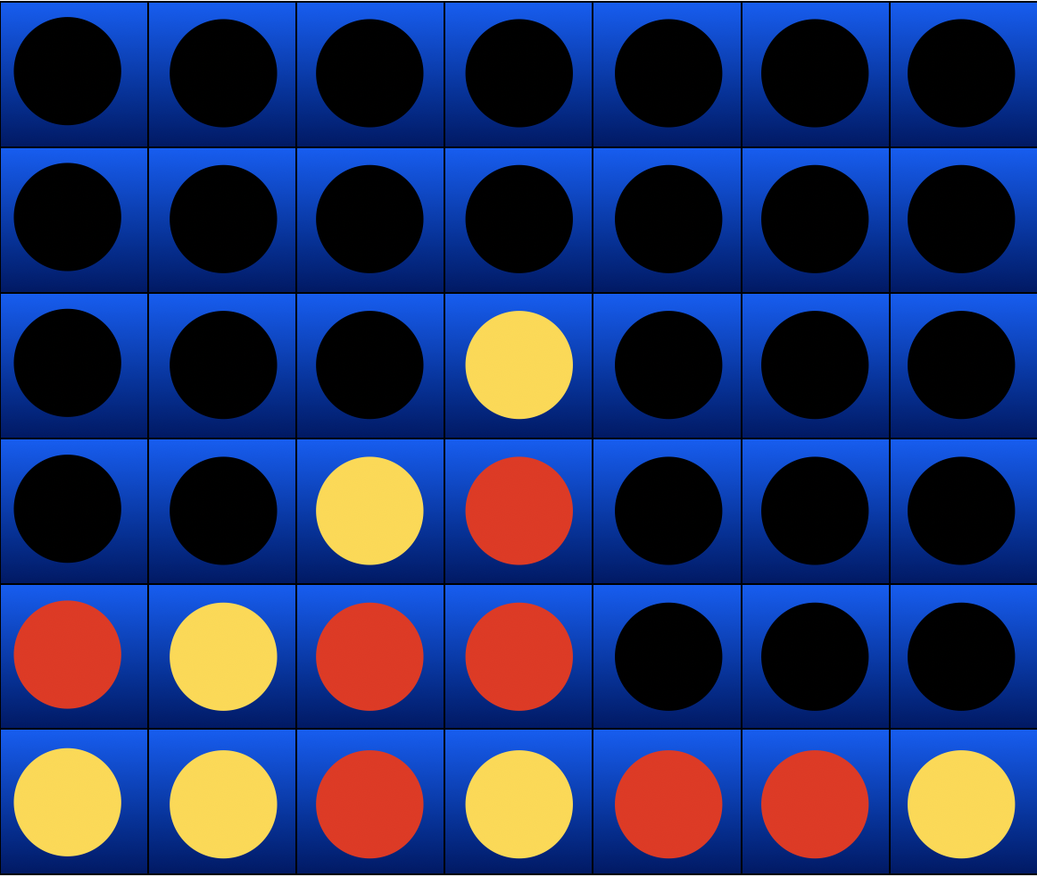
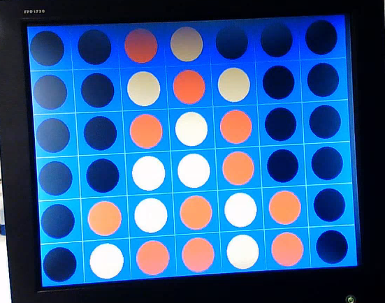
In the image above, if the human player were to place their disc in column 2, they would be able to win on their next turn in column 2. We wish for our AI to ensure that it blocks the human’s connect four in this situation. In the below image, we see that this is indeed the case.
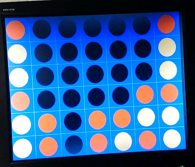
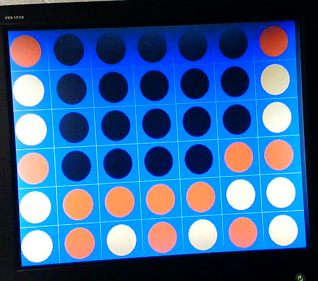
One other feature that we wished for our AI to have in order to simulate a real human being is the ability to not give the opponent free blocks. This situation can be seen in the image below.
In the image above, we see that if the AI were to play in either column 1 or 2, the human player would be able to block the AI’s connect four. This “self-destructive” behavior is undesirable, as it lessens the ability for more advanced gameplay (such as setting traps). As such, we ensure that the AI does not self-destruct, as can be seen in the image below (where the AI does not place in either of those columns if not forced to).
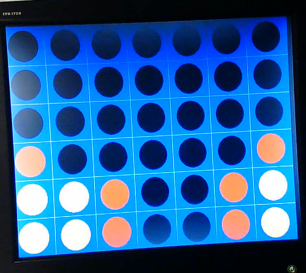
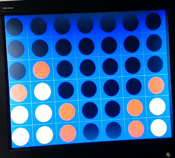
One last feature that we added to our AI was meant to let the AI perform slightly advanced gameplay. This feature actually creates an exception to the above feature, where we do not allow the AI to self-destruct, enabling self-destruction if the move effectively sets up a trap. We can illustrate this example in the image below.
Note that in the above example, the human player cannot play in column 6 (or else the AI will win). It also cannot set up a winning move in its one move. However, on the AI’s turn, the AI is guaranteed to win if it places in column 6. Note that this is because placing in column 6 will force the human player to block the diagonal victory for the AI by placing in column 6. However, this sets up yet another AI victory with another diagonal in column 6, showing how the AI is guaranteed to win. As such, in this situation, we wish for the AI to place its move in column 6, which we see occurs in the image below. This sets up a trap that guarantees an AI victory, and is one exception we make to the feature of how the AI should not destroy its own winning possibilities.
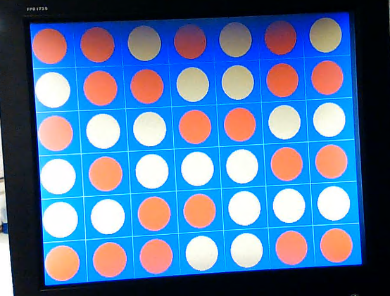
One final thing to note about our AI is that we did not wish for it to win 100% of the time. While we also would have been resource limited on the FPGA if we were to traverse the entire state space to determine moves that are guaranteed to win, we also realized that this would not have been a fun, productive playing experience for the user. As such, our AI was designed such that it made moves like an above average AI player would (by using tactics such as looking at future states and making guesses as to the opposing player’s strategy for placing their moves), but it is not unbeatable. In the image below, we see that it is indeed possible to play the AI to a draw. This allows for the human player to train their Connect Four capabilities to a level high enough to consistently win against the AI.
The one final evaluation criteria we used for our AI design was correctness. To ensure that our design outputted valid outputs (to ensure safe execution) and was consistent with the logic we implemented, we ensured that the results seen from our VGA display showed parity with our ModelSIM simulation of our AI. For the most part, this parity was retained throughout the design. However, at one point in time, we did see disparities between ModelSIM and the FPGA VGA output. To debug this, we therefore utilized SignalTap to probe the internal signals of the FPGA and see where discrepancies occurred. An image showing the two disparities are shown below.
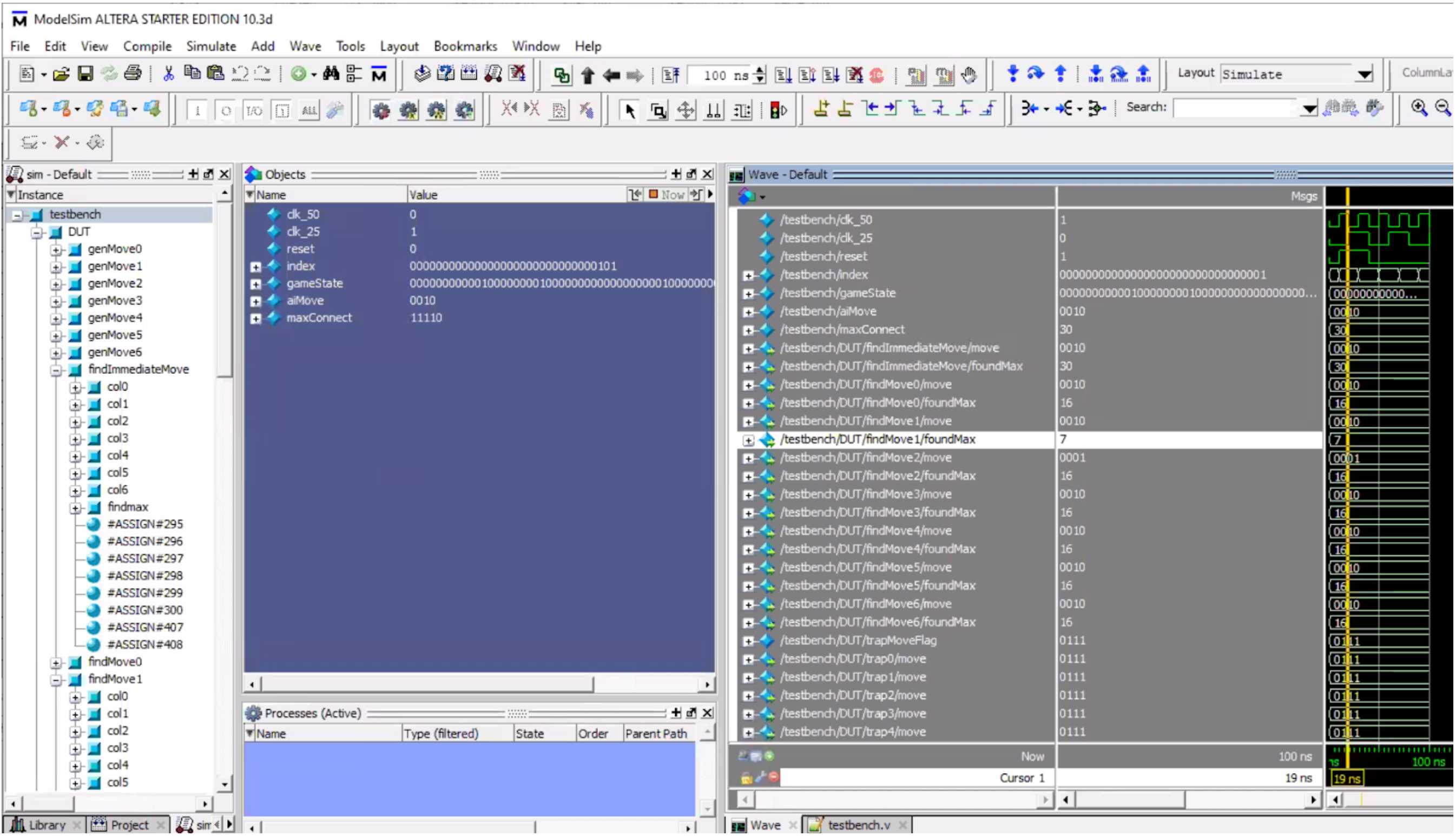
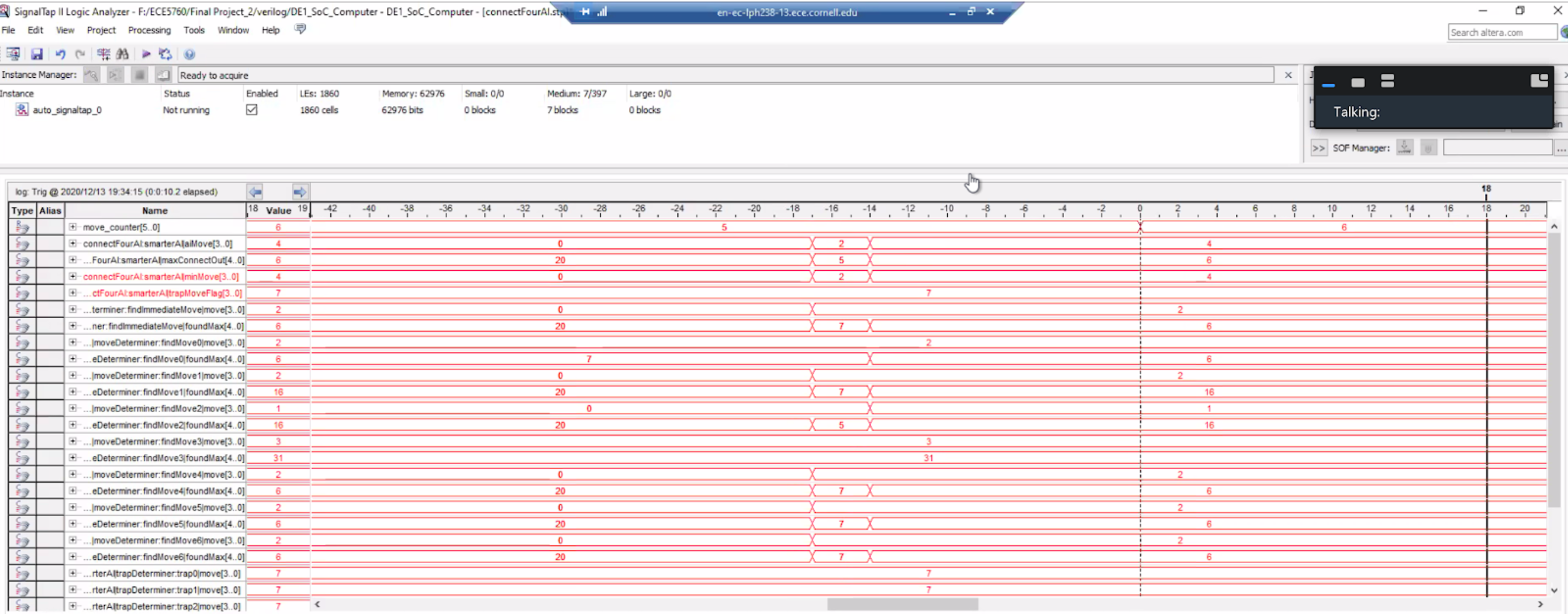
From the images, we see that ModelSIM expects the AI to output a move in column 3 (represented in binary as 2, since we start indexing at 0). However, in SignalTap, we see that the AI actually ends up outputting in column 6. We see when comparing the two images that the weights given to various moves differ from what we expected, indicating an error in our logic somewhere. At first, we had all our crossCheck wires were red, which indicates that Quartus optimized some bits away. This was bad behavior, since we sometimes needed the uppermost bits (when set to 10). To fix this, we added a /* synthesis keep */ directive. However, this did not end up fixing this disparity. Upon closer inspection, we realized that our code did not protect against accessing array values that were “out of bounds” (i.e. not in the bit length of the signal, meaning we wrapped around and overflowed). This unsafe execution, while abstracted away by ModelSIM, proved to be problematic on actual hardware in the FPGA, which required us to rewrite our index check instructions. After making sure all bit accesses were in range and did not wrap around, we achieved parity with ModelSIM once again, ensuring correct execution of our AI on the FPGA.
The last check for correctness involved ensuring that our C program correctly checked for game over conditions, and that the values that were being sent between the FPGA and the HPS were being sent and read properly (ensuring correct game state updating logic and a correct SRAM setup). The game over checks were validated by playing through numerous games with our complete game framework. The game state update logic was validated by print statements in the C code and manually checking that the game states were updated correctly. Finally, the SRAM setup was validated by using SignalTap to ensure the data that was being read was consistent with what was being sent (and also, was inherently validated by correct execution of our AI). Through all of these checks, we were able to ensure overall correctness of our entire AI design and Connect Four framework.
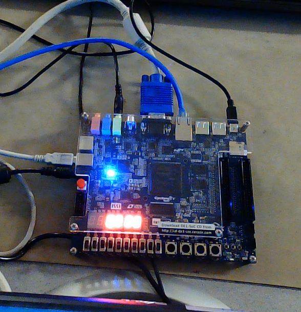
After all of the aforementioned was completed, we had a fully functional AI on an FPGA. A user was able to play against the AI by inputting their column placements on a terminal, and the VGA would display the Connect Four board in real time with no flickering or other interference. All of this made for a nice, elegant gameplay experience.
Overall, our AI design ended up performing as expected. As described in the Results section, the AI was able to successfully prioritize executing particular moves depending on the situation it finds itself in. This enabled the AI to provide a relatively difficult challenge to the user, and forced the user to learn more about Connect Four strategy (such as how to set up traps) in order to actually win.
Regarding things we might do differently for our AI design, there are additional features we may be able to add to it. For example, we currently drive the VGA display using the HPS. By integrating VGA display into the FPGA, we could be able to update the display faster (this may even allow us to add fancy animations, such as showing discs dropping and making a sound when they hit the bottom, which was not done due to the delay from the HPS in constantly writing and overwriting a disc).
For functionality, one feature that could be added to the AI would be detection of human traps. Currently, the AI does not try to prevent the player from setting up their own traps, which was useful for beginners who are training and learning more Connect Four strategy. However, by adding detection of human traps (perhaps as an advanced game mode the user could choose to play against), we would be able to further the capabilities of our AI.
One other feature that could be added to our AI is the capability to look further ahead at more game states. Recall our current pseudo-minimax algorithm caps its max depth for the state space search at one move ahead. This enabled us to fit all our logic in a clock cycle. However, if we were to parallelize our calculations and span multiple clock cycles, it could be possible to look more moves ahead in the future. Then, in conjunction with our minimax implementation, we could also implement another fundamental concept of reinforcement learning in artificial intelligence known as SARSA update. SARSA update is a methodology that assigns values to different moves by adding your current reward for a state + action you can take, as well as the perceived value you can receive from future states and actions you can play in those. This type of update also scales the weight of future rewards down due to uncertainty in the system (i.e. there is no perfect heuristic to predict how your opponent will play), which allows an AI to more accurately predict which move would be beneficial to play in. Should our AI design go down this route, we can also see the scenario where we implement true machine learning and have our AI train its state-action values and player heuristic by means of playing numerous games, after which it will have a good idea of which move to play depending on what the human plays.
The current design of our AI conforms to all applicable standards, and is able to successfully run on an FPGA+HPS and play through complete Connect Four games. The design itself does not utilize anyone else’s design (though the framework for the C code address setup was consistent with the example setup given on Bruce Land’s ECE5760 website for Lab 3, and the Verilog FSM also used a similar outer FSM framework to the one in Lab 3). The design was run on an Altera DE1-SoC board that had an FPGA and an Arm Cortex M9 HPS; the only Altera IP used on the FPGA was the on-chip SRAM and ALMs. We did not use code in the public domain during the design of our AI and Connect Four framework, and we did not reverse-engineer a design, meaning there were no issues with patents or trademarks. No non-disclosure agreements were needed to be signed to get parts, and the FPGA was provided to us for use by Cornell University as a part of its ECE5760 class. Since our design itself is primarily an HDL implementation of a known algorithm that has numerous opportunities to be iterated upon, it would likely be more beneficial for our design to be a part of the public sector for all to expand upon.
Work Distribution: The entire team worked together on all parts of the project to produce the Connect Four game and AI described above. Collaboration was primarily performed by use of numerous Zoom meetings throughout the semester, due to the remote nature of the semester. We would all get together during both our assigned lab sections, as well as other open lab sections, in order to meet and work on the project. We also scheduled several other times outside of lab to meet up and work.

Andrew Tsai

Megan Backus

Rohan Agarwal
FPGA
The group approves this report for inclusion on the course website.
The group approves the video for inclusion on the course youtube channel.
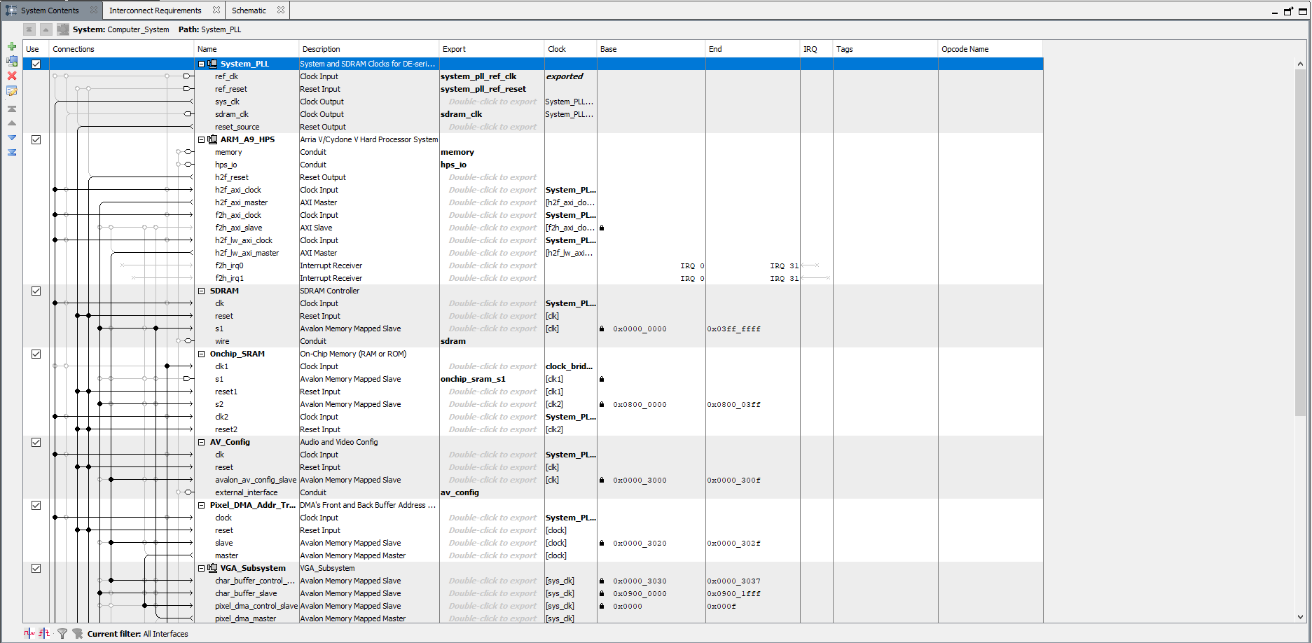
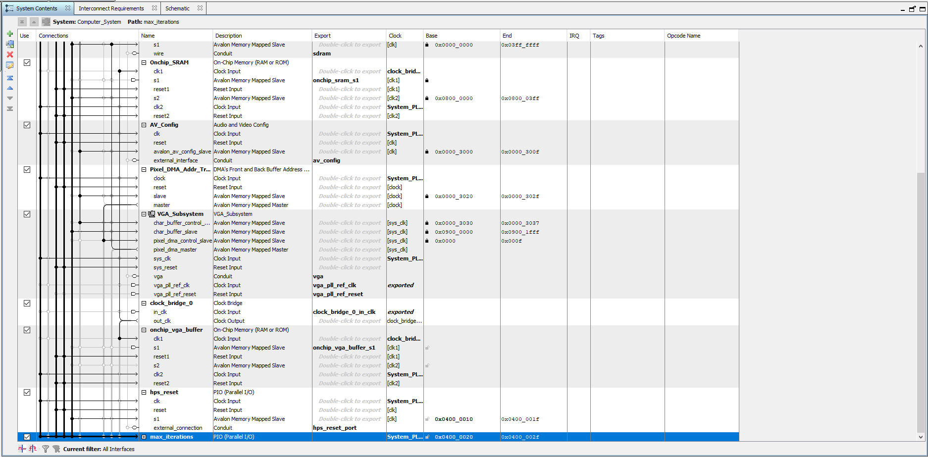
Qsys Layout
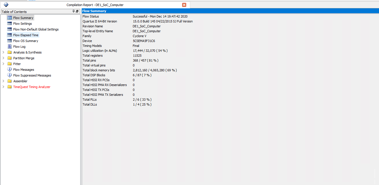
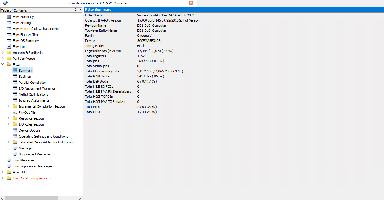
Quartus Compilation Report
1. Top Level Verilog
2. AI Compute Module
3. Simple Defensive AI Compute Module
4. Connect Four Framework + VGA C Code