ECE
5760 Final Project: Car Driving
Video Game
by Lu Liu (ll654), Xu Chen (xc255)
1.
Introduction
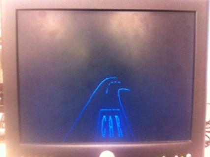
The
car driving game displays the 2-D top view, with optional 3-D static view of a
lone car driving on the road. On the screen, the front of the car is
fixed at the centered bottom of the screen while the layout of the road ahead
is moving accordingly. The player needs to drive
the car through
the end of the road without hit either side of the road throughout the game.
User will operate on a fake
steering wheel, gas/brake pedals.
On the hardware side, for user control interface, we have built the fake steering wheel, gas/brake pedals with basic wood board, hinges, springs, screws, switches, accelerometers, potentiometers, etc (reused from previous lab). For other parts (display and computation) in the system, we have used the LCD TV screen, Mega 1284 microcontroller and DE2 FPGA board which are supplied by lab. These are essential hardware equipment for this project.
On the programming side, we have implemented the system hardware with Verilog using SOPC builder from FPGA board and coded the drivers and application in C through NIOS II. Also, we have applied the mathematic calculations and matrix conversion for car coordinate computation algorithm.
2. High
Level Design
(1) Rationale and sources of your
project idea
In fall 2013, we have built a 2-D car
parking video game in course ECE 4760. It was a successful game and very useful
for car parking simulations. However, due to the lacking of computing power in
hardware (Mega 1284 microcontroller), the game can only be
displayed in a small screen without any movement in the surrounding scene.
Thus, it confines the car movement to small regions and restricts the car with
very little speed.
The rationale of this project is to reuse the
user control interface and hardware, in addition with a more powerful FPGA board, to
improve the game with higher resolutions and faster speed and larger driving
areas. The car driving game can also serve as a virtual driving simulator,
together with previous car parking game, to assist people in the process of
learning to how to drive.
(2) Logical structure and background math
The logical
structure of this project can be divided into three parts: hardware reconstruction and
modification, hardware system building and video game programming.
The hardware reconstruction and
modification readjusts and connects the previous hardware to the DE2 FPGA
board. The data from the sensors in the steering wheel, gas and brake pedals
are sent to Mega 1284 microcontroller for analog to digital
conversion. The digital outputs are then sent to FPGA board for processing and
computing. Thus, the new structure enables combination of analog and digital
design. This provides us with better computing ability and higher complexity in
this project.
The hardware system building implements
the hardware system on FPGA board using Verilog. The system consists of a
‘microcontroller_sensor’ and a ‘Video_System’ block.
The ‘microcontroller_sensor’ implements a protocol to communicate
with Mega 1284 microcontroller through parallel interface. The SOPC builder inside Quartus package
constructs a customized ‘Video_System’ which outputs the video
image on VGA monitor and processes the results from NIOS II processor.
The video game processing involves many background mathematic calculations such as road construction and rotation, coordinate rotation calculation, 2D to 3D image conversion, etc. It also includes video signal processing, such as line plot, character printing and so on. (Please also see the section below ‘Program/Hardware design’ for more details.)
Road Construction and Rotation
Instead of moving the car on the screen, this video game moves the
surroundings within the picture around the car. This way allows larger moving
regions for the car and enables us with higher speed in the game.
To construct the road, the program uses three functions (‘road_left_line’,
‘road_right_line’ and ‘road_middle_line’) with three arrays accordingly to compute the current road position and plot it onto the VGA monitor. The arrays are generated through Matlab and store the relative
coordinate information of the points compared to their previous points on the
road (assuming zero angle of the car head compared to its initial position).
The three functions use the array and the current absolute angle of the car
head to compute each point of the road and draw them onto the VGA monitor.
The following figure shows the complete process of road construction and
rotation.
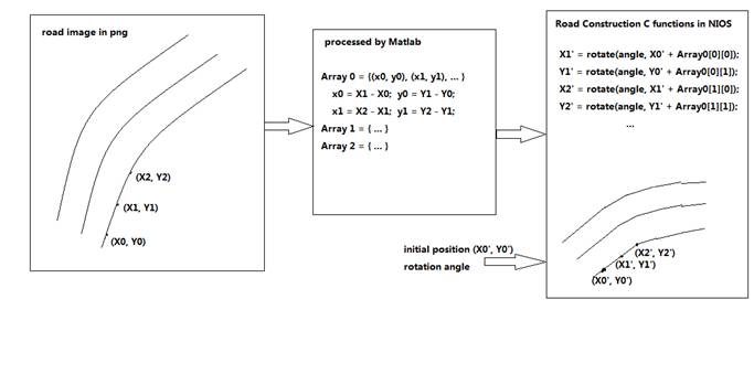
Road construction and rotation
Coordinate
Rotation Calculation
When the
steering wheel is positioned to some degree, rather than being held straight,
car will go as a path of circle (the orange line in the picture below).
However, in this case, instead of seeing the car path on the screen, we want to
convert the car turning into road rotation. So compared with our car parking
game last semester, the road rotation scheme follows a different calculation.
For the car driving game, we want the VGA monitor always display the 2-D
road map, given the car head at the center of the bottom of the screen. As
shown in the picture to the left, the two blue rectangles show two screen
displays when car turns for![]() ,
and the green lines indicate the curbs of road. So after the car turning for
,
and the green lines indicate the curbs of road. So after the car turning for ![]() ,
the curbs will be as the red line and green line in the picture to the right
below. So it’s obvious that for each point on the curb, it rotates for
,
the curbs will be as the red line and green line in the picture to the right
below. So it’s obvious that for each point on the curb, it rotates for ![]() with a center of the circle. Usually, the
center of the circle is located at y coordinate equals to 480, and with radius
depending on the speed of the car, and the current position of steering wheel.
with a center of the circle. Usually, the
center of the circle is located at y coordinate equals to 480, and with radius
depending on the speed of the car, and the current position of steering wheel.
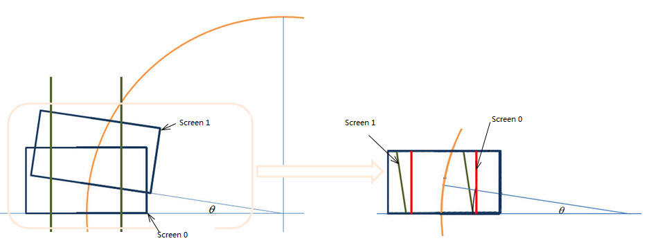
Coordinate rotation example
So let’s assume the coordinate of one point on Screen 0 is (x0,
y0), and the radius of the circle path is r. So the vector from the target
point to the center of the circle is
![]() where mid_x is the x coordinate of
the middle of the screen 320, and max_y is the y coordinate of the bottom of
the screen 480
where mid_x is the x coordinate of
the middle of the screen 320, and max_y is the y coordinate of the bottom of
the screen 480
So ![]()
![]()
And after rotate for ![]() with the center of the circle, and the
radius r, we have the updated coordinate
(x1, y1) of the target point:
with the center of the circle, and the
radius r, we have the updated coordinate
(x1, y1) of the target point:
![]()
![]()
The result in Matlab is shown in the
picture below. The red line is the curb of a straight road. After the car turns
3o with radius 400, the curb of the road is the blue line.
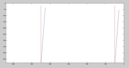
Matlab display for
road rotation
This function is used to update the first point of one road curb in our
project.
3D to 2D
Plane Conversion
In our project, one of the features is show the 3D ground plane of the track, just as the pictures below.
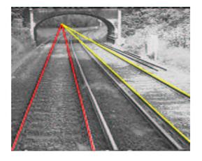
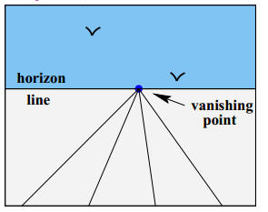
Ground plane
It’s the 3D to 2D perspective projection. Normally, a homogeneous 3*4 projection matrix can be used to convert 3D point coordinates into 2D image point coordinates.
The (X, Y, Z) is the coordinate of a 3D point, and (x1, x2, x3) is the image coordinates.
Then 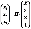
Where H is the 3*4 homogeneous projection matrix. And the image coordinate is
![]() ,
, ![]()
Specifically, we need the planar homogeneous matrix that converts the point coordinates on the 3D plane (in our case, the ground plane) to the image point coordinates. To do this, we used the function [H,Hnorm,inv_Hnorm] = compute_homography(m,M) found online (http://www.mathworks.com/matlabcentral/fileexchange/41511-light-field-toolbox-v0-2/content/LFToolbox0.2/SupportFunctions/CameraCal/compute_homography.m) to generate the planar homogeneous matrix. This function uses homogeneous coordinates in both 3D and image plane, to generate a 3*3 homogeneous matrix, which is used to convert plane from 3D to image. We defined the coordinates of several key points of the curb as the input of this function, and use the matrix to convert other 3D points of the curb to 2D.
The 3*3 homogeneous matrix we use in our project is 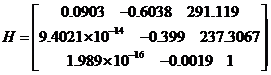
In our project, we got the plane conversion as the following pictures.
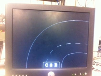
Top view track Track after perspective projection
(3) Hardware/software tradeoffs
The hardware and software tradeoff in this project
mainly involves the complexity and capability tradeoff. On
the hardware side, the capability of the FPGA is limited
in terms of memory capacity and processing speed. On the software side, the available
resources need to be allocated properly in order to accomplish a fast yet
complex video game. For example, in this project, the main memory components
used by FPGA board is SRAM and M4K blocks. The SDRAM is mainly used by VGA
controller for VGA display. Thus, only 105 m4k blocks (420 KB) is available for
processor and other hardware in system. As most of the data constructing the
road is stored in arrays, we could build a long road with many memories used. We
could also use memory to save computation time such as trigonometry by storing
results into arrays. Therefore, there is a trade-off between complexity of the
game (long road) and speed of the game (fast computing time thus surrounding
change).
(4) Relationship to available IEEE, ISO,
ANSI, DIN, and other standards.
This project will be following IEEE. The connection between the FPGA and VGA
monitor display will use VGA display standard. Also, the connection between mega1284 microcontroller and FPGA board is using parallel interface standard.
(5) Patents, copyrights, and trademarks
The video output plots are referenced from previous projects from Fall 2013 and previous
labs in this courses.
Copyrights from previous project:
//
Mega644 version by Shane Pryor
// mod by brl4@cornell.edu'
Copyrights from previous lab2:
// Terasic Technologies
// Altera Coopration
3.
Program/Hardware Design
(1) Hardware Construction Details.
We reuse our devices (steering wheel, gas and brake pedals) from ECE4760 last semester in this project. And we also use the microcontroller mega1284p as the ADC to convert the signal generated from sensors to digital signals. After some calculation, then transfer the digital signals through parallel wires to GPIO of DE2 board. We use the GPIO0 pin IO_A0 to IO_A10 on the DE2 board for the sensor signals, in which 4 pins are for the steering wheel, 3 pins for the brake pedal, and the other 3 pins for the gas pedal.
In the main while loop of the mega1284 microcontroller, it periodically gathers the signals from 2 accelerometers from the steering wheel, and 2 potentiometers from pedals. Then the microcontroller is responsible for calculating the steering wheel rotation degree and gas/brake degree, and encoding different degrees with binary. One thing that has to be careful here is that normally the microcontroller outputs 5V digital signal, while the GPIO of FPGA board can only stand for 3V, so we use a simple voltage division circuit to convert the 5V to 2.5V, which can be used by the FPGA board. After the FPGA board gets the digital signal from GPIO, it decodes from the binary code to the true steering wheel rotation degree and gas/brake degree.
The connection between the microcontroller and the FPGA board is shown below:
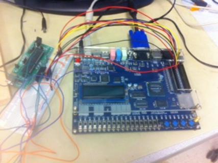
Connection between Mega1284 and FPGA DE2
The steering wheel and gas/brake pedals are shown below:
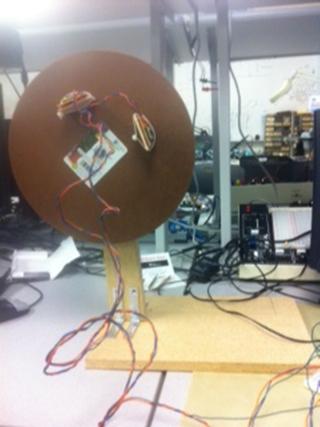
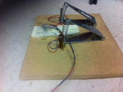
Steering wheel Gas/brake pedals
(2) Hardware System Details.
The
hardware design in this project is not so difficult. The basic hardware design
strategy is to use SOPC
Builder inside the Quartus software package to build a Video System with NIOS
II processor and Video output display. The built system has enough general
purpose I/O ports so that we can connect user interface signals (such as gas or
brake level information) and also debugging information to/from NIOS processor.
The system also contains a ‘microcontroller_sensor’ module
which connects to the I/O pin of FPGA board and receives ADC signal from Mega 1284 microcontroller and decodes it into separate information, such as gas level, brake
level and steering wheel angle from user control interface. These decoded
information, together with debugging wires (called ‘bogus’ bus), is
then packed together as one 20-bit input bus to the Video System module and
used by NIOS processor. The block diagram below shows the hardware system
design used in this project. The screenshot also shows the SOPC builder
information.
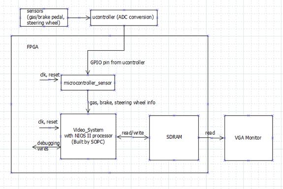
Hardware System Block Diagram
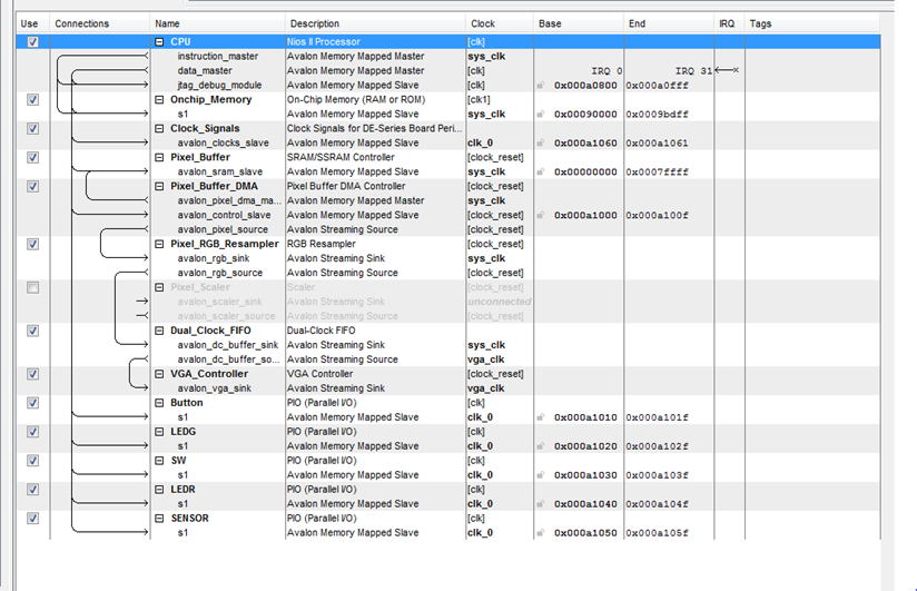
SOPC Screenshot
There are lots of floating calculations in our project, for example, to
calculate the road coordinate rotation, and to do 3D to 2D plane conversion, and
the floating calculation is rather slow. So we use the Nios II floating-point
custom instructions to accelerate arithmetic functions executed on float
variable types, by simply setting the Nios II processor Floating Point Hardware
in SOPC (shown in the picture below).
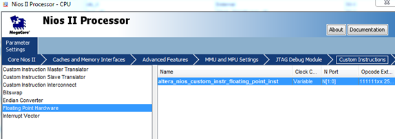
Setting NiosII floating-point custom instructions
(3) C Program Details.
The program
for this video game consists of two parts: low-level ADC conversion code
in Mega 1284 microcontroller and high-level video game design C code in NIOS II processor. (The details are described in the table below.)
The low- level driver functions use the ADC in the microcontroller to read the
sensor readings and return the value as the status indication of the vehicle
driven by the player. This includes the following functions:
Driver functions:
|
int potentiometer (int voltage) |
This function is used as gas pedal level indication. It receives the ADC readings of a potentiometer and returns the value 1 to 3 indicating the gas pedal level. |
|
int abs_wheel_angle (char acc_0, char acc_1, int prev_wheel_angle) |
This function is used to indicate the absolute position of the steering wheel. It receives the ADC readings from two accelerometers attached to the steering wheel and returns the an 0-359 integer indicating the absolute turning angle of the steering wheel. |
|
int relative_wheel_angle (int init_angle, int acc_0, int acc_1) |
This function is used to indicate the relative steering wheel angle. It receives an 'init_angle' as previous absolute steering wheel angle (ranging from 0 to 359) and two accelerometers readings and returns an integer indicating the relative turning angle of the steering wheel. |
|
int car_angle_compute (int wheel_angle)
|
This function is used to indicate the absolute car wheel angle. It receives a steering wheel angle (ranging from -450 to 450) and returns the corresponding car wheel turning angle (ranging from -45 to 45). |
Video game design functions:
|
int resistance (int speed, int acc) |
This function returns the resistance
confronted by the car. The faster the car drives, the larger the resistance
is. The resistance ranges from 0 to 9 as the car speed ranges from 0 to 9. |
|
int verify_point(int x, int y) |
This function verifies
whether an input point (x, y) is within valid range. If it is, 0 is returned,
otherwise 1 is returned. Note: the valid range is defined 40 pixels wider
than the screen resolution, i.e. x ranges from (-40, 680), y ranges from
(-40, 520). This is because the distance between each point on the road is
maximum 40 pixels. |
|
int VGA_point(int x1, int y1, short pixel_color) |
This function draws a point (x, y) on the screen. Note: if the point is not within
the range of the screen. Nothing will be drawn. And a value of 1 will be
returned. |
|
void VGA_box(int x1, int y1, int x2, int y2, short pixel_color) |
This function plots a box defined by the two diagonal points (x1, y1) and (x2, y2) on the
screen. The box is filled with the color ‘pixel color’. |
|
int VGA_line(int x1, int y1, int x2, int y2, short pixel_color) |
This function plots a line on the screen defined by two points (x1, y1) and (x2,
y2) with color ‘pixel color’. It returns 0. |
|
int VGA_point_read(int x1, int y1) |
This function reads the color of the point (x1, y1) on the screen and returns the result. |
|
int road_left_line(int *x0, int *y0, int angle, int pixel_color, int *road_idx, int skip) |
This function plots the left line of the road starting on point (x0, y0) with color
‘pixel color’ and starting with section index of ‘road_idx’
on road array ‘road_map’. The result plot will rotate the
original road by ‘angle’ and also adjust (x0, y0) value if it is
not within valid range. This function also returns 1 (game failed) if the any
point on the road line hits the ‘car’ region defined in the road.
It returns 2 (game passed) if the road line is finished and returns 0 in all
other cases. |
|
int road_right_line(int *x0, int *y0, int angle, int pixel_color, int *road_idx, int skip) |
This function plots the right line of the road starting on point (x0, y0) with color ‘pixel color’ and starting with section index of ‘road_idx’ on road array ‘road_map_right’. The result plot will rotate the original road by ‘angle’ and also adjust (x0, y0) value if it is not within valid range. This function also returns 1 (game failed) if the any point on the road line hits the ‘car’ region defined in the road. It returns 2 (game passed) if the road line is finished and returns 0 in all other cases. |
|
void road_middle_line(int *x0, int *y0, int angle, int pixel_color, int *road_idx, int dash_init_length, int dash_init_color_invert, int skip) |
This function plots the middle dash line of the road starting on point (x0, y0) with color ‘pixel color’ and starting with section index of ‘road_idx’ on road array ‘road_map_right’. The result plot will rotate the original road by ‘angle’ and also adjust (x0, y0) value if it is not within valid range. In addition, the starting section of the dash line is of length ‘dash_init_length’ with color equals inverted ‘pixel_color’ if ‘dash_init_color_invert’ is set to 1. |
|
void threeD_conversion(int x, int y, int *x_out, int *y_out) |
This function computes a point (x, y) from 2D view on the screen into a 3D view
point (x_out, y_out). |
|
void landscape(short color) |
This function draws a landscape scene in 3D view. |
|
int fixmult(int x, int y) |
This function multiplies two fix number and returns the result as a fix number. |
|
int VGA_char(int x, int y, int c, short pixel_color, int row_size, int col_size) |
This function draws a character onto the screen. The character is chosen from
character table indexed ‘c’ and its position starts at point (x,
y), with color ‘pixel color’. The size of the character can be
amplified by either ‘row_size’ or ‘col_size’ argument
or both. |
|
void rotate(int *x0, int *y0, float relative_angle, int car_radius, int speed) |
This function rotates a point (x0, y0) by angle of ‘relative_angle’
with radius equals ‘car_radius’. If the angle is 0, it shifts the
point up by ‘speed’. |
|
void draw_car(void) |
This function draws the head of the car onto the screen. |
|
void plot_3d(void) |
This function plot the current 2D-view of the screen into 3D view. |
|
void plot_fail (void) |
This function plots the
word ‘FAILED!’ onto the screen. |
|
void plot_pass (void) |
This function plots the
word ‘PASSED!’ onto the screen. |
|
int main () |
The main function does the initialization of the video game including plot landscape, initialize car variables. Then it constantly execute the video game (in an infinite loop) by updating sensor readings, updating the road coordinates, computing the game variables, displaying the car status readings onto the VGA monitor and checking the results when done. |
4. Results of the design
Our designed video game consists of one driving
stage with the following features:
1. A finish and a restart button.
2. Auto result checking and status report when failed or finished
(passed).
3. A complete user control interface includes steering wheel, brake
pedal, gas pedal and FPGA switches and buttons.
4. 3D
view switching from 2D view and reverse.
5. Multiple
gas and brake levels.
6. VSYNC frequency:
60Hz, period 64us. Computation and plotting time: 30ms (full computation and
plotting) and 240us (full computation with no plotting).
Our project involves many human interactions to control the movement of the car
in the driving
game. When driving, to get a better control, we need to allow the car to move
in multiple speeds and brake in multiple strengths. Thus,
we need the ability
to have the road lines move less than a pixel on the screen for each frame refresh period, and it will result in the
computation for data type 'fix' which is time consuming. Therefore, when the
car is moving,
especially rotating, the image seems
shaky and sometimes even less continuous. This is also because of
the discrete movement computation logic.
Another factor of the shaky image is because of
the long computation and plotting time. The main functionality of the VGA controller used in this project is reading
the SDRAM and refreshing the screen. In order to avoid flickerings
and tearings on the screen, we have to update the SDRAM only during vertical
synchronization (VSYNC) period. The VSYNC frequency measured in the lab is 60Hz
and its period is 64us. However, our computation time measured is either 30ms (full computation and plotting) or 240us (full
computation with no plotting). Either one exceeds the VSYNC time, thus resulting in SDRAM updates
during screen refreshes, which contributes to the shaky image.
For this design, the main issue in safety is the hardware connection, i.e. connecting the microcontroller with FPGA board. The output voltage of the microcontroller is 5V while the FPGA board I/O only accepts 3V. Thus, we need a voltage divider to make sure the input voltage to FPGA board is not too high. This process involves measuring the voltage from the outputs of the voltage divider before connect the wire to the pins on FPGA board. We enforce our safety by consulting with instructor first to make sure it is doable. Our design has no wireless communications involved so we didn't encounter many interference issues with other people's design. The video game we designed can be operated by most people whether with or without driving experience. The game itself requires user to be able to fully control the steering wheel, gas and brake pedals, and switches and buttons.
5.
Conclusions
Our design has met our expectations. It consists of all initially intended features of fully functioning user control interface, multi-level speeds, auto-checking and 3D and 2D features. In order to accelerate arithmetic functions executed on float variable types, we use the Nios II floating-point custom instructions. The thing we might do next time is to further optimize the computation logic and memory usage (maybe use some of the unused section of SDRAM or change into a larger FPGA board) to speed up the video game.
As
for ethical considerations, the main idea behind this project is to assist
people in practicing driving skills. The game, including all the
user control interfaces, simulates the real driving environment. Thus, the game
is intended to help people with or without driving experience gain some general
feelings and practices of driving a car on the road with a safe virtual
environment yet still practical enough. In this way, it contributes to the
safety of the public by helping drivers to drive safely and
also aiming at reducing accidents and injuries in parking lots.
Also, in developing stages, we have made the following decisions and actions that conform to IEEE Code of Ethics. First, some of our basic video functions are referenced from previous projects and previous labs. We have properly referenced this in both our code and report, thus credit properly the contribution of their work. Second, in the choice of material that we used to construct our hardware equipment, we have chosen to reuse the hardware built from previous project. In this way, it is cheaper and convenient, and more importantly, it is more environmentally friendly compared to rebuild everything. Thus, we make decisions consistent with the health and welfare of the public. Also, during our process of building hardware equipment, we have asked instructor for help in how to establish connections between microcontroller and FPGA, because the process might cause damages to FPGA board if not handled properly. Thus, by asking for assistance in the tasks that we have are not sure of shows our responsibility to improve the understanding of technology and its appropriate application, and potential consequences. Last, in every stage of our design, we have consulted the instructor for viability of our next steps and ideas. Thus, we have maintained and improved our technical competence and undertaken technological tasks after fully disclosure of pertinent limitations.
We use the SOPC design from the previous lab2, and some of our code of mega1284 from our ECE4760 final project, and one matlab code downloaded from the website to calculate the homogeneous matrix.
6. Appendix
7. Reference
Matlab code for homogeneous matrix, http://www.mathworks.com/matlabcentral/fileexchange/41511-light-field-toolbox-v0-2/content/LFToolbox0.2/SupportFunctions/CameraCal/compute_homography.m
Perspective projection: http://www.robots.ox.ac.uk/~ian/Teaching/CompGeom/lec2.pdf
Our ECE4760 final lab: http://people.ece.cornell.edu/land/courses/ece4760/FinalProjects/f2013/ll654_xc255/ll654_xc255/ll654_xc255/final_project.html