Re-inventing the Personal Computer:
FPGA Command Line Interface and File System
ECE 5760 Final Project, Spring 2015
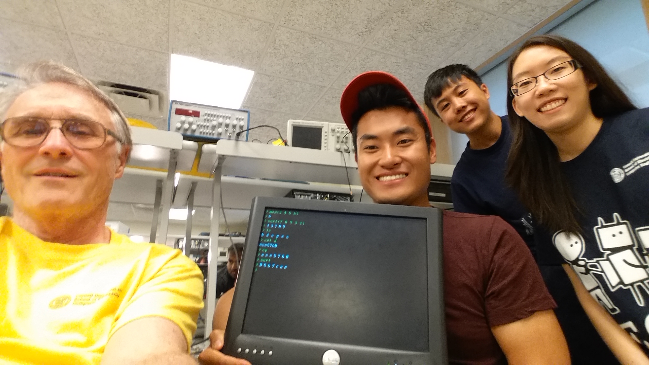
Shela Wang (sw679), Victor Fei (vf63), and Richard Quan (rq32)
Introduction
Our project connects a VGA monitor and a keyboard to an FPGA via an Altera DE2 development board to create a system resembling a personal computer. By simulating a traditional command line interface (CLI) on the VGA screen, users can perform certain operations through the CLI. Additionally, we utilized the DE2 board's built-in SD card reader to allow users to import, manipulate, and save portable data, effectively creating a simplified file system for the FPGA.
The project uses the Pancake stack CPU to handle the high-level computations and tasks. Thus, one of the results of our work on this project was implementing several new functions for the Pancake programming language library. The project also includes some preliminary work interfacing the FPGA with the on-board SD card, without using Nios II or C. We have compiled a list of the new features that we implemented, which we believe may be helpful to future students. This list is found in the Useful Features section of this page.
Interface
Our primary interaction with the Pancake stack CPU is through the keyboard. We implemented a command line interface to take in commands. The interface is able to interpret three main groups of commands: arithmetic calculations, file system access, and array operations.Arithmetic Calculations
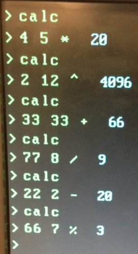
Arithmetic calculations is launched through typing in the command calc, then followed by the arithmetic operations. We use reverse Polish notation for the operations. The supported operations are addition, subtraction, multiplication, division, and modular.
Array Operations
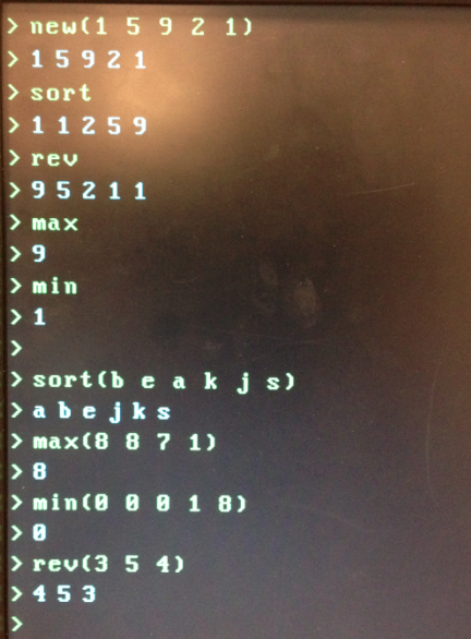
We implemented various array operations to demonstrate that our system has some support for data structures. Many of the array operations also intend to be an addition to the Pancake programming language. The array operations that are supported are: new(), max(), min(), reverse(), sort() .We could directly perform these array operations on a new array entered through the command line or on an array that is stored in the system variable array, which holds the array that was just referenced to using any of the array operations. The array operations work both on integers and chars, since we look at the ASCII values of the array element to perform sort, max, and min operations. The format of each array element is only in 8 bit chars. Thus, our system does not support double digit numbers for the array.
File System Access
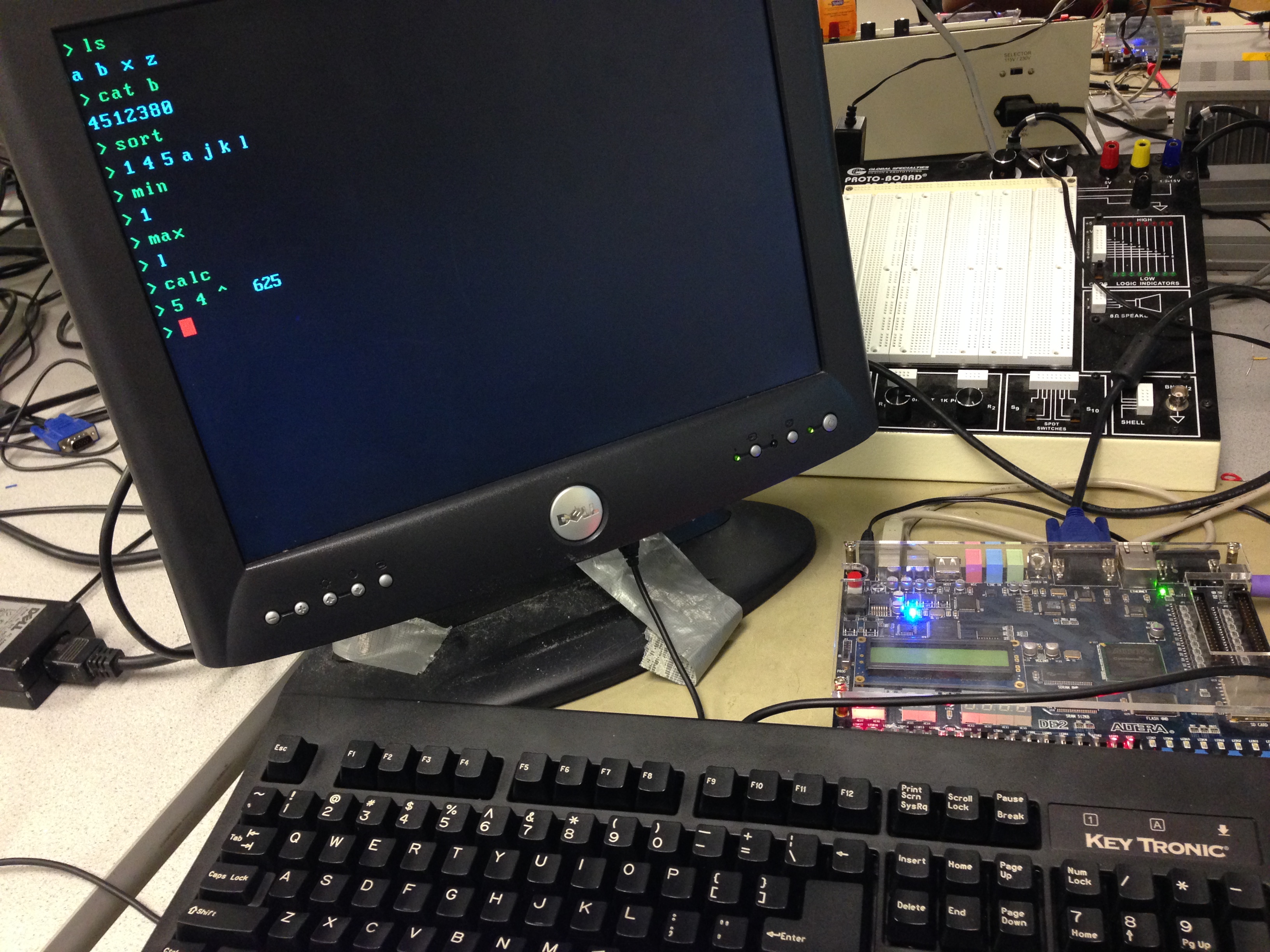
We implemented commands ls, cat, rm and mk to interact with the file system.- ls list all the files that exist on the file system--stored on the SD card.
- cat <file name> displays the content of a the file.
- mk <file name> <file content> creates a new file named <file name> with content <file content> stored to the SD card.
- rm <file name> removes the file from SD card
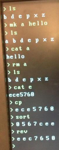
Additionally, the cp command copies the array that was recently read from the SD card to the variable array in memory (SRAM) so that we can perform array operations on data from the file system. In the figure above, we see that cat e and cp copies string ece5760 into memory, and we then apply operation sort and rev to the data read from file e on the SD card!
Design
Block Diagram | Connections | Difficulties & ChoicesBlock Diagram
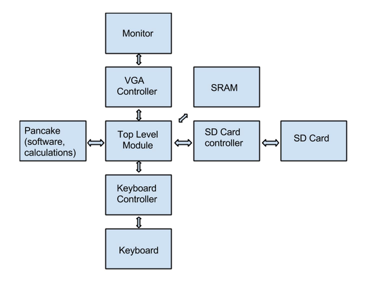
The figure below illustrates the major components of the system. The hardware interface consists of an FPGA on the DE2 board with an SD card reader connected to a PS/2 keyboard and a VGA monitor. We use a Pancake processor running on the FPGA to interface between the software (Syrup) and hardware (Verilog) components of our design. The FPGA accepts user input via the keyboard, interprets and processes the command through Pancake, and outputs the I/O through a command line interface (CLI) displayed on the VGA, in a way reminiscent of personal computers of yore. The SD card reader sends and receives data in the same fashion.
Connections
The figure below is a photograph of the physical connections and ports used on the DE2 development board.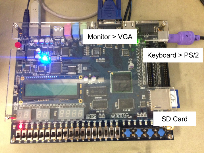
Software
When we started this project. The Pancake programming language came with very few functions. Consequently, part of our project is to extend the Pancake programming language library and to add many basic functions that should belong to a programming language. Our hope was to make the Pancake programming language friendlier to other users.
Addition to the Pancake Programming Language Library
The functions that we could be useful to the Pancake library include:- itoa: printing number to VGA in decimal format
- mod: modular operation
- div: integer division
- power: exponentiation operation
- bubble_sort: perform bubble sort on an array in ascending order
- print_array: printing an array to VGA
- max: return the max of an array
- min: return the min of an array
- reverse: reverse an array
The modular function is implemented using subtractions. This algorithm for modular is very standard.
power (exponential) function is implemented using multiplication.
The bubble sort algorithm we implemented is a very standard bubble sort algorithm. In particular, our Pancake version of the bubble sort is based on this one:
Function Specific to the Command Line Interface
In addition to those functions that could become an extension to the Pancake programming language library, we have also implemented functions that are specific to our project.
- calculator : interactive calculator through the command line.
- clear_screen : clear the content on the command line screen and start the cursor from the top of the screen
- clear_buffer : clear the buffer of line that the cursor is on.
- new_arr : creating a new array and store it in memory
- cp : copy the array that read from the SD card to the memory
- type_character : interprets a key pressed on the keyboard
- type_character_helper: displays a character on the VGA and adds it to the character buffer.
- draw_rectangle : draw a rectangle on the VGA, used to draw the blinking red cursor
- parse_file_cmd : implements the command ls, which reveals what files are on the SD card
- read_sd : read the content of a file contained on the SD card into the memory
- read_byte_sd : read a single byte from the SD card at a specific address
- write_sd : create and write a file to the SD card
- write_byte_sd : write a single byte to the SD card at a specific address
Calculator
The interactive command line calculator implements a FSM to interpret the commands from the user.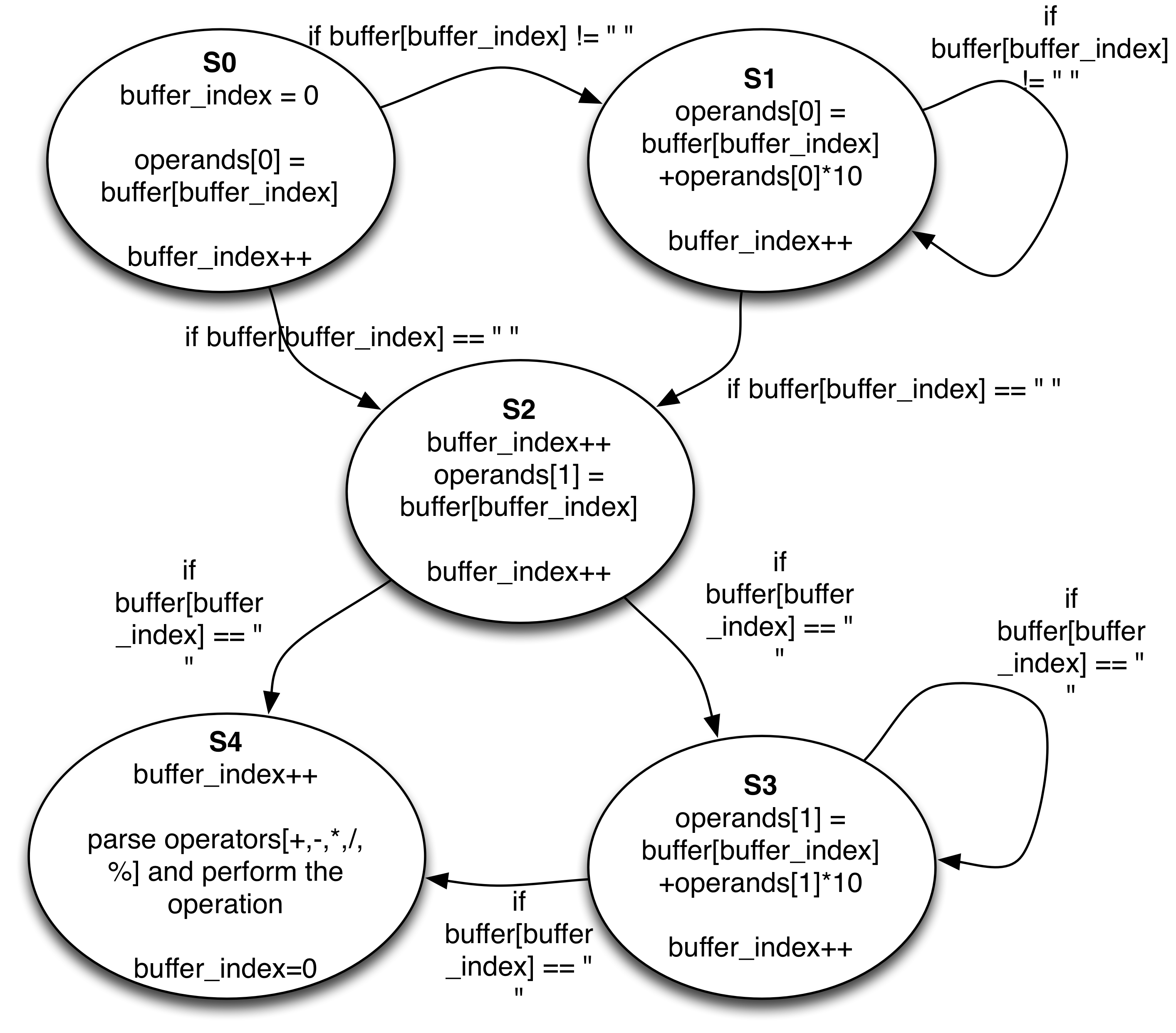
File System-Related Functions
File System
The file system uses the functions mentioned above to read and write from the SD card. We decided that, to simplify the system, file names would only consist of one letter, allowing for 26 possible files. The SD card that we used had a capacity of 32 MB, or approximately 60,000 512-byte sectors. As discussed in more detail later in this document (see Useful Features - SD Card Controller), our system only implemented reads and writes at the sector-level, rather than the byte-level, leaving us with approximately 60,000 spots to read and write on the SD card. To fit our intended 26 files, we decided to set a fixed size of 2000 bytes maximum for each file. We believed that this would be sufficient for the purposes of our computer, which only has limited text-editing capabilities, anyway.
When a file is to be written, the first byte of the file is written as a 1, to show that it is valid. This scheme works because when an SD card is formatted clean, every sector of the card is set to 0, except for the 0th (first) sector. This sector is reserved, so we actually started our first file (file 'a') at the 200th sector, rather than the 1st sector, to avoid writing over this reserved space.
Once the first "valid" byte is written, then the rest of the bytes of the file are written. After that, an "end of file" byte is written to the sector immediately following the last character of the file. We chose 3 for this purpose. (In fact, 3 represents "end of text" in ASCII notation.)
Reading a file simply follows this format. First, the 0th byte of the file is read: If it is 1, then the system continues reading the rest of the file. Otherwise, the file is not valid, and the system does nothing. Then each byte is read and printed to the VGA monitor as it is read. When the "end of file" byte is read (3, in our cases), then the reading stops.
A very helpful tool that we found when trying to test the write capabilities of the system was HxD - Freeware Hex and Disk Editor. This tool allows you to read the raw hex data that is on an SD card plugged into your computer, so you can see whether or not your writes are successful.
Hardware
Keyboard Controller
The keyboard controller used in this project was from Skyler Schneider's "Falling Sand Game", ECE 4750 Fall 2010. The keyboard controller utilizes the PS/2 port located on the DE2 board. When a key on the keyboard is pressed, this is called a "make" event. When a key is released, it is called a "break" event. At each event, a "scan code" is output from the keyboard controller. This scan code should not be confused with ASCII codes, as the two systems have different mappings to each character. Thus, when a key is pressed on the keyboard, the corresponding scan code is output from the controller, which then must be translated into an ASCII code in order to be used by the rest of our system.
For our purposes, we mostly only cared about "make" events, that is, when a key was pressed on the keyboard. However, for determining whether or not the user was holding down the Shift key, we also needed to look at the "break" events for the left and right Shift keys.
Keyboard Scan Code Look-up Table
As discussed in the section below, Design Difficulties, one way that we decreased the code size of our Pancake program was by moving the keyboard scan-code to ASCII look-up from the Pancake code to a hardware module in Verilog. The look-up module takes three inputs: a keyboard scan-code, a "shift" flag, and a "caps lock" flag. The latter two are simply 1 if shift or caps lock is pressed, respectively, or 0 if not pressed. The output of the module is an 8-bit ASCII number that corresponds to the letter that was pressed on the keyboard. For example, the keyboard scan-code of the letter A is 173, while the ASCII representation of A is 97 for lowercase and 65 for uppercase. Say that the user hits the A key on the keyboard. If caps lock or shift is pressed (i.e., one of these inputs is 1), then the output of the module would be 97; otherwise, the output is 65. This value goes straight to an input on the Pancake minicpu module, where it can be used by the Pancake program.
SD Card Controller
The SD card controller that we used was implemented completely in Verilog and was found in Theo Engel's P856 Minicomputer project. The Verilog module for this controller is located at sd_card3.v Further discussion on how we used this module can be found later in this document, in Useful Features - SD Card Controller.
Design Difficulties and Choices
Minimizing Code Size
The maximum code size for a Pancake program is 0xFFF, or 4095 lines/operations. If a program gets any bigger than that, it will not be possible to load the program onto the FPGA. Our software deals with many cases and performs many functions, so at times we struggled keeping our code size under this limit so that we could continue with our project.
In some cases, this meant sacrificing certain fun but not completely necessary features. In other cases, it mean streamlining our code or moving parts of the software into hardware, when possible. For example, originally we mapped the keyboard scan codes to ASCII values within the Pancake code. However, to cut down on code size, we moved this function to a hardware look-up table, which took the form of a module in our Verilog code.
Minimizing Input/Output Ports
Once it is instantiated by an upper module, the "minicpu" module provided by Bruce represents the Pancake CPU and its input and output ports. One important thing to remember when using this module is that it has limited input and output ports — eight of each. Thus, one aspect of our design that we had to manage was what data we were sending in and out of the CPU so that we would not run out of ports. We originally based our initial code on Bruce's 3 CPU Example. Since we only needed one CPU, we found that after removing two of the three in the example, we could in fact free up several ports.
Multiple Key-Presses
One small issue that we encountered early on in this project's development was the problem of differentiating multiple key presses of the same key. For example, if we only had one input to the Pancake CPU that contained the code for the key that was just pressed, we could have a hard time knowing if that key was just pressed once or pressed multiple times beforehand. Our solution was to have a flag called "toggle" that toggled between 1 and 0 whenever a key on the keyboard was pressed. This toggle flag was input into the Pancake, which kept two variables: toggle and toggle_prev. On each iteration of the main while-loop, the program checked if toggle and toggle_prev were different. If they were, then a new key on the keyboard must have been pressed; otherwise, no key was pressed.
Results
Speed and Accuracy | Safety | UsabilityFor the results of the demonstration, please refer to Interface section.
Speed and Accuracy
Calculations
Our calculator is able to correctly calculate arithmetic operations accurately. However, one bug that we have not been able to fix is when the operands have more than two digits. The state machine of the calculator technically supports multiple digits, but in reality the operands cannot be more than two digits. This is a bug that we have not been able to figure out.
Array Operations
All the array operations correctly perform operations on any given array. There are no known corner cases that trigger those algorithms to fail. We implemented bubble sort as the sorting algorithm. Bubble sort is known to have a big-O speed of O(n^2), which is very slow. For our demo purpose, we used a small array, which does not affect the speed. However, if we were to use a very large array, we probably would observe a delay in sorting.
File System
Our file system is simple but functional. However, due to the issue of only having sector-level access rather than byte-level access, as later discussed in the section Useful Features - SD Card Controller, file operations are slow. The most noticeably slow operation is ls, which quite slowly prints out one-at-a-time which files have content in them. This slowness is present because the system has to sequentially read twenty-six 512-byte sectors in order to figure out which files are valid and which are not.
Safety
Our system has no moving parts and consists solely of a DE2 development board, keyboard, VGA monitor, and SD card. These components are fairly familiar to the typical user, and we therefore do not foresee using our system as being any more dangerous than using a regular personal computer.
Usability
The system is usable and fun to use as a command line interface. For most commands, such as the calculator and array functions, there is no no perceivable delay between when the user enters the command when the response is displayed on the screen.
On the other hand, because of the way that we implemented the file system, most of the file-related commands, such as ls (list files), mk (make new file), and cat (show file contents), can take a second or two to complete.
A feature that would improve the usability of the system would be error messages. For example, if a user tries to show the contents of a file that does not exist, then the system would show on the screen that no such file exists. In the system's current state, the user does not receive any indication when a command or file name is not valid.
Conclusions
Success | Features | Standards | Considerations | ImprovementsSuccess of the Project
Our project was a success. While we were not able to implement all of the features that we had initially set out to create — such as a full-fledged interpreter and the ability to run programs directly from the SD card — our system is usable and has several other fun and useful features. In addition, we believe that future students may find some use in certain features that we implemented. These features are detailed in the Useful Features section below.
Useful Features
This section lists some of the features that we implemented for this project, which we believe may be useful for future students working with the Pancake stack CPU, an SD card, or a PS/2 keyboard on the DE2 development board.
New Pancake functions
As mentioned above in the Software section, some new functions that could be useful to the Pancake library include:
- itoa: printing number to VGA in decimal format
- mod: modular operation
- div: integer division
- power: exponentiation operation
- bubble_sort: perform bubble sort on an array in ascending order
- print_array: printing an array to VGA
- max: return the max of an array
- min: return the min of an array
- reverse: reverse an array
Pancake re-programming script
After making changes to the .cmp file in which the Pancake code is written, a multi-step process needs to be completed before the new code can be programmed onto the FPGA. The steps are as follows:
- Compile the Pancake code using Bruce Land's Syrup compiler in MATLAB.
- In Quartus II, select Processing > Update Memory Initialization File.
- Run the Assembler by selecting Processing > Start > Start Assembler.
- Program the FPGA.
Luckily, a full compile of the HDL is usually not required if the only changes were in the .cmp file; however, we decided to simplify steps 2 through 4 of this process by creating a Windows batch script called pancake_program.bat.
A small amount of setup is required to use this script:
- Find the "Quartus bin" directory on your computer. On the lab computers, this is C:/altera/11.0/quartus/bin.
- Copy this path to your clipboard.
- Follow the directions at this link to find out how to modify the PATH system variable on your computer. (Follow the Windows 7 instructions for the lab computers.)
- Without adding any spaces, add a semicolon to the end of the value for PATH, then paste in the path to the Quartus bin directory.
- Click OK.
- Restart the Command Prompt, if you have it open.
- Ensure the pancake_program.bat file and the .cmp file for your project are in the same directory.
- Navigate the Command Prompt to the directory that holds the .bat file.
- Compile the Pancake program using Bruce's MATLAB compiler.
- Enter into the Command Prompt "pancake_program.bat" (without quotes).
- Your new software should now be on the FPGA!
- Repeat steps 3-5 as necessary.
SD Card controller
Using a Verilog implementation of an SD card controller that we discovered online (see References), we were able to passably read and write an SD card using only Verilog (i.e., without using Nios II).
It is worth noting that in our implementation, a single "write" to the SD card in fact writes an entire 512-byte block, or "sector," of the SD card. Meanwhile, a "read" from the SD card reads the entire 512 bytes of a block but only keeps the last byte to display on the monitor. This scheme results in passable but certainly not optimal file accesses, and future work done using this SD card controller could include research into how to improve reads and writes.
Also note that the SD card controller may only reliably work with SD cards with storage capacity below 2 GB, as SD cards with more than 2 GB (high-capacity cards) require a different initialization sequence that is not handled in the controller used in this project.
Below is a brief overview of the inputs and outputs to the SD_Card module, which acts as the SD card controller in Verilog.
Inputs to SD_Card module
| Port Name | Bit Width | Description / Notes |
|---|---|---|
| iCmd | 2 | Command to SD card - read (01), write (10), or none (00) |
| iScAd | 32 | Byte address on SD card to write to or read from (depending on iCmd) |
| iWsD_DATA | 8 | Byte to write to SD card (if iCmd is "write") |
| iRST_n | 1 | Reset line - connect this to your global reset signal |
| iCLK | 1 | Clock - this module appears to be fast enough to handle 50 MHz |
Outputs from SD_Card module
| Port Name | Bit Width | Description / Notes |
|---|---|---|
| oCmd_Ack | 1 | Signal to upper module that read/write command was accepted |
| oBreak | 1 | Signal an input break to upper module (i.e., byte available from SD card) |
| oRsD_Data | 8 | Data byte read from SD card (if oBreak == 1) |
| oAckOutput | 1 | Signal to inform the upper module that output byte is being send to SD card |
| oRW_Ready | 1 | Signal to upper module that read/write command is processed and finished |
| oOperational | 1 | Outputs 1 when SD card is in init state/ready - after reset, this should eventually become 1 by itself; check this before proceeding with reads/writes |
| Response | 8 | SD card response byte of a write command (see References) for links to more details |
SD Card Interface with DE2
| Port Name | Bit Width | Description / Notes |
|---|---|---|
| SD_DAT | 1 | SD Card Data (SPI: DO output on card) - connect to SD_DAT port on DE2 |
| SD_DAT3 | 1 | SD Card Data 3 (SPI: CS, chip select input on card) - connect to SD_DAT3 port on DE2 |
| SD_CMD | 1 | SD Card Command Signal (SPI: DI input on card) - connect to SD_CMD port on DE2 |
| SD_CLK | 1 | SD Card Clock (SPI: Clock input on card) - connect to SD_CLK port on DE2 |
Keyboard scan-code to ASCII look-up table
As discussed in Hardware, we implemented a keyboard scan-code to ASCII look-up table, as a Verilog module. While such a module is not necessarily difficult to implement, we hope that having our work available will save future students some time.
Conformity to Standards
Our project does not use very many industry standards, as very few are required to run this system. The main standard we use is the ASCII format used to convert hexadecimal numbers into characters for the PS2 keyboard inputs. We encode 128 specified characters into 7-bit binary integers using a hardware implemented Look-Up Table. Additionally, we use the Secure Digital standard for reading and writing to the memory of the SD card.
Legal and Ethical Considerations
In developing this project, we followed the IEEE Code of Ethics, being careful in the development of our project to engineer our product in a responsible manner. We investigated the possible safety concerns that could come along with this project, and determined fully that our project would be safe even if accidents were to occur. We minimized risk in order to be consistent with public safety and welfare in mind.
In addition, we sought honest criticism at every stage of the development of our project, including from Bruce Land, our TA Deepak, and from our classmates to make our project better. At many points, we had small errors in our code or in our design, and we have acknowledged the contributions of all those involved in this project. We have been honest and realistic in the abilities and limitations of our project throughout. This is exemplified by our statements about how the project is limited in its current form, but there is plenty of room for extensibility. We have also been honest with the drawbacks of our project in terms of usability and modularity.
Finally, we have sought to improve understanding of technology through our project. We make all of the information available to the public in order to encourage others to build similar products if they are interested. This project is a good example of how computers were built from the ground up, and we hope that this reaches those who have similar interests and want to build similar systems.
Possible Improvements
Error Messages
Having meaningful error messages when a user enters an invalid command would improve the usability of our system. In our current system, if a user enters an invalid command or tries to display the contents of a file that does not exist, then the CLI simply does not output anything. In contrast, if a user enters an invalid command in Linux, for example, the CLI will display a message saying that the command was unsuccessful so that the user knows to try a different command.
Handling Negative Numbers
Currently, our arithmetic operations only support positive numbers. Since we use the same hardware for negative numbers represented in two's complements, adding support to negative numbers should not be too difficult a task. However, we would have to improve on our command line intepreter to be able to parse negative numbers.
Interpreter
Originally, our personal computer is supposed to be programmable. Since we did not have enough time, we were unable to implement this feature. Additionally, with the existing software, we have already run out of addresses for the program (the max number of instructions is 0xfff, the address is 12 bit). To implement an intepreter would require more software, which implies that we would have to extend the hardware to make the instrucitons more than 12 bits.
Efficient SD Card Access
In the project's current form, a single "write" to the SD card actually writes an entire 512-byte "sector" of the SD card. Thus, the storage capacity on the SD card is reduced by a factor of 512, while the time required to read and write from the card is increased by a factor of 512. Improvements to reading and writing the SD card would greatly enhance the usability of the system, because file reads and writes would be much faster, and users would have the ability to create more files.
Hierarchical File System
Customizable file names and the ability to create and navigate between directories would make our file system seem more like that of a regular computer. A real bonus would be to implement FAT32-style reading and writing so that files could even be transfered between the FPGA and other computers with SD card slots.
Appendix
Code
The entire Quartus II project for this project, along with the .cmp file in which the Pancake program is written, as well as the pancake_program.bat script mentioned above, is included in this .zip file:
Parts List
- Altera DE2 Development Board
- VGA Monitor
- PS/2 Keyboard
- 32 MB SD Card
All of the parts used for this project (except for the SD card) were borrowed from Bruce Land's lab.
References
- PS/2 Keyboard Controller from Skyler Schneider's "Falling Sand Game", ECE 4750 Fall 2010
- Information on the SD card communication protocol
- Further information on SD cards by F. Foust at Michigan State University
- Information on SD card responses
- Pancake Stack CPU on the ECE 5760 webpage
- HxD - Freeware Hex and Disk Editor — a very important tool for making projects with SD cards
- SD Card Controller from Theo Engel's P856 Minicomputer project
- The Verilog for the SD card controller is in sd_card3.v
- Bubble sort algorithm in ascending order
Acknowledgements
We would like to thank the course instructor, Bruce Land, and the TA Deepak for their help and advice throughout this project.