Introduction
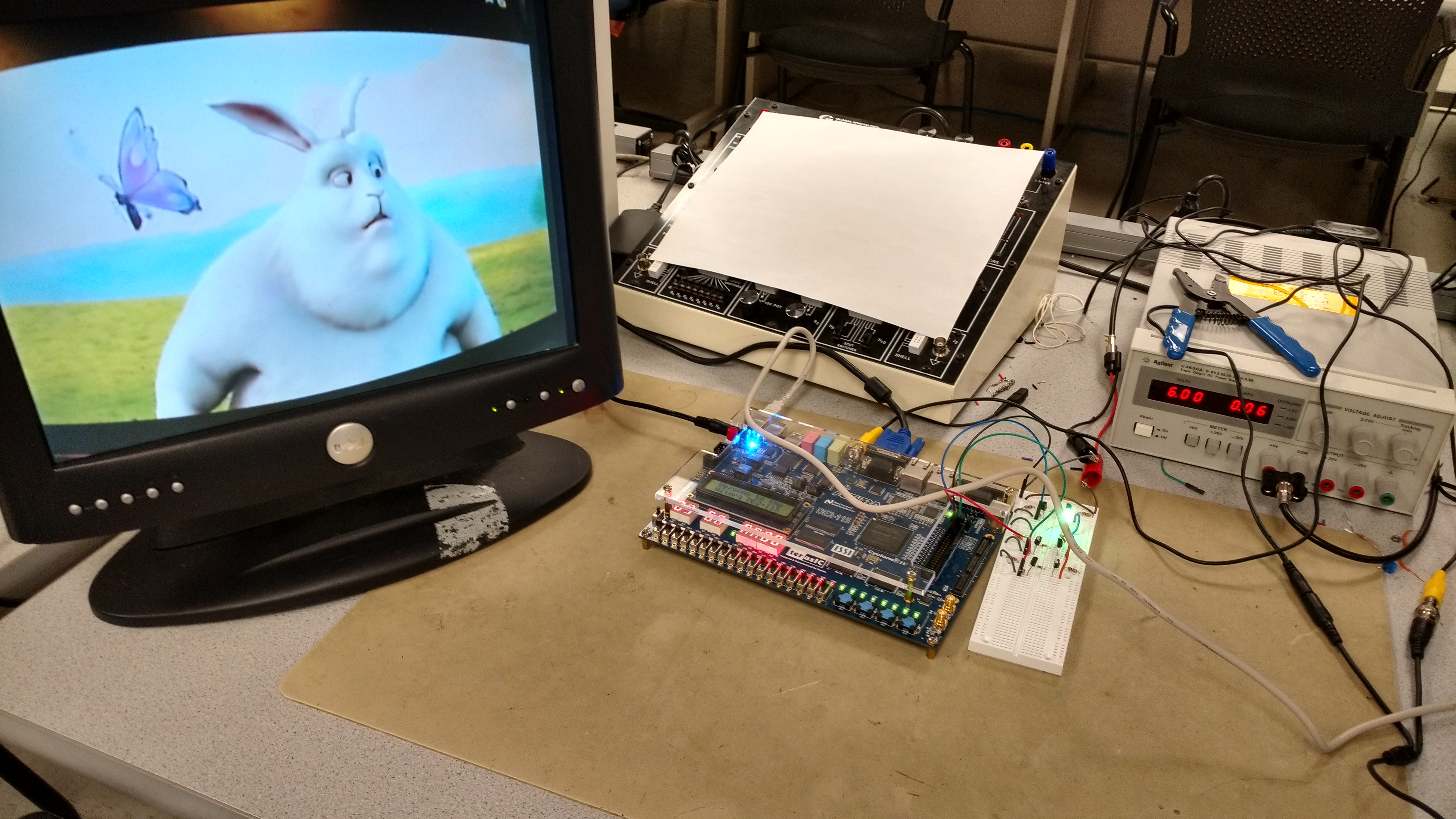
For my ECE 5760 final project, I have created a real-time system that can use an NTSC video signal to simulate the lighting effects of a TV in a low-power fashion. This enables such applications as real-time ambient TV lighting, as well as simulating a TV's light in an unoccupied home to give the appearance of an occupied home. For this to be believable, the system must be able to keep up with the flickering and update speed of a TV signal, and therefore requires a dedicated, real-time processor. The goal of this project was to create a general purpose algorithm that can accomplish this task, and use PWM outputs to drive a larger circuit that controls an RGB LED for verification. The user can send in any NTSC video signal and see the immediate changes on the LED as the video's dominant color changes.

My system uses some specialized versions of known algorithms for the specific purpose of achieving this goal on an FPGA. Additionally, using a VGA monitor and a mini-camera, I was able to test the system to make sure it was robust and configurable for different signals. Human perception was a major factor in this project, as the goal was not to make a believable fake TV light simulator, but one that accurately matched what a human would believe is the dominant color of the current frame. While there are already products that randomly change color to simulate a TV, I wanted to create a system that went a step further and provided the ability to augment the TV-watching experience should the user choose.
High-Level Design
Rationale and Inspiration
The inspiration for this project came directly from Dr. Bruce Land. Bruce mentioned the problem of making an unoccupied house look occupied, and how the DE2-115's TV decoder would make for an obvious way of taking in a TV signal and simulating its lighting effects. As time went on and I did more research about how to best extract the dominant color of a frame, I realized that my method could also be used for ambient lighting in a darkened TV room. Rather than using an expensive power LED for this prototype, I decided it would be best to prove the concept using a simple RGB LED controlled by a PWM signal, which could easily be connected to other circuitry depending on what the user desires. This system can simply be the backbone, having an NTSC input and 3 PWM outputs.
Background Math
There are a few mathematical concepts implemented in this project, but overall the concepts are somewhat simple. It should be noted right off the bat that this project owes its mathematical basis heavily to Erwin Zwart and his excellent writeup about his Hue Camera app and how he accomplished this feat for his app. The background information that follows will somewhat mirror that of Zwart's writeup, but with more focus towards the parts that I used in my project.

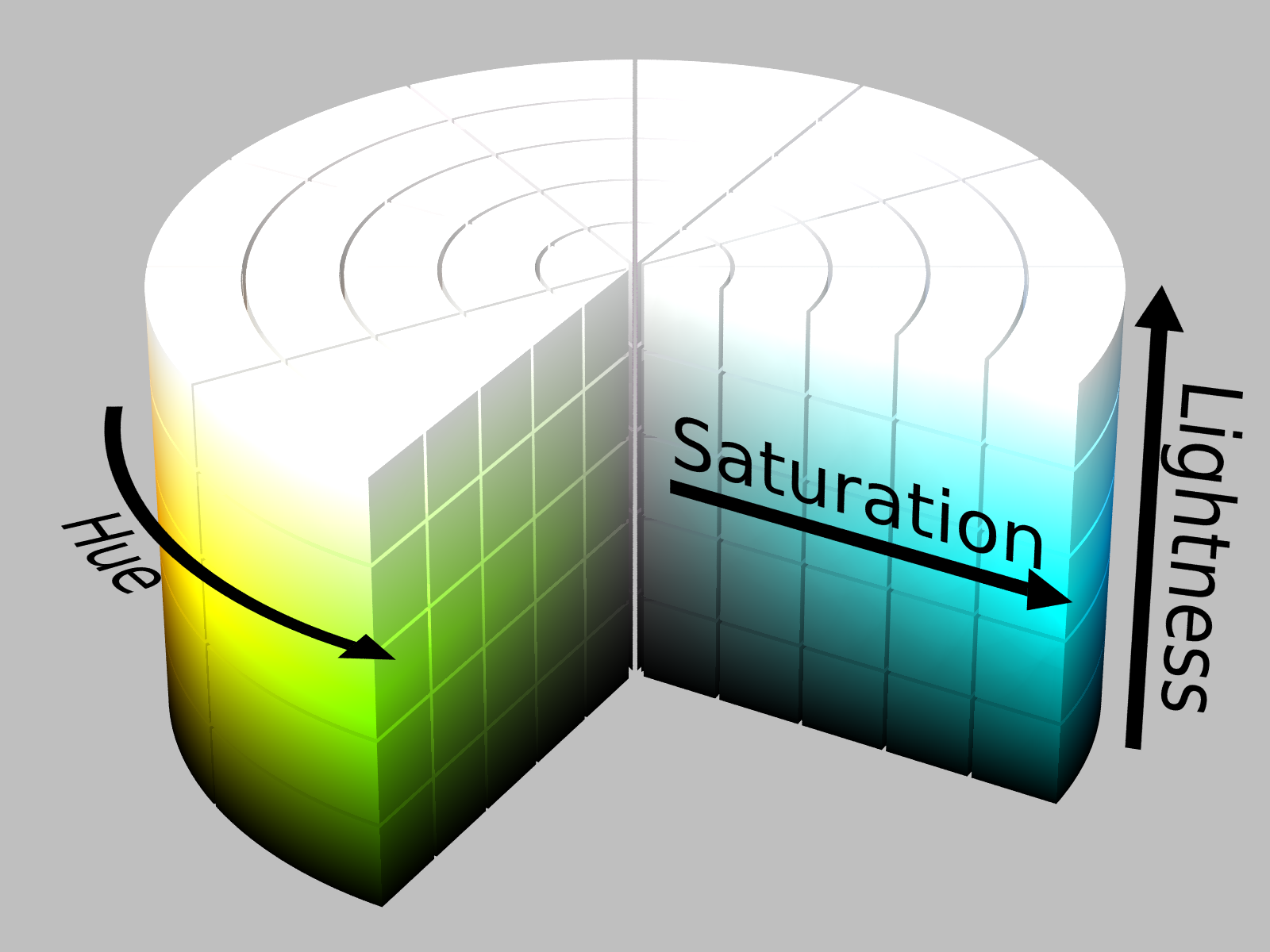
In order to fully understand the background mathematics for this project, we first need to understand two representations of color. The first, which is most common and widely known, is RGB space. RGB space defines a 3-dimensional space with a pixel's content of Red, Green, and Blue. The space encompasses all colors, and is also how data is displayed on many displays, including VGA monitors. The TV decoder in the DE2-115 sample code uses RGB as the final representation of the incoming NTSC stream. However, RGB space does not provide a very easy method of calculating how "important" a pixel is to the dominant color of the screen, so it becomes necessary to move to HSL space (Hue, Saturation, and Luminance, in this project). The figure to the right shows lightness instead of luminance, but the two are very similar (discussed more below). We can convert from RGB to HSL based on these equations, assuming that r, g, and b are [0,1] scaled versions of R, G, and B values.
$Sat = \left\{\begin{array}{ll} \frac{d}{max(r,g,b)+min(r,g,b)}\ when\ Lum\lt0.5\\ \frac{d}{2-(max(r,g,b)+min(r,g,b))}\ when\ Lum\geq0.5\\ \end{array}\right.$
$Lum = \frac{max(r,g,b)+min(r,g,b)}{2}$
Hue defines where the color lies on the color wheel, and can be visualized as a continuum over 360 degrees of a circle. Saturation is a measure of how intense the color is. As we can see from the figure on the right, as saturation goes from 0 to 100%, the color becomes brighter and more vivid. The luminance defines the perceived brightness of a color, which is important to differentiate it from lightness. Each hue has a natural lightness, which might not appear to be the same luminance for different hues. By using luminance, we can say that the most important colors are closer to 50% luminance, giving us a more meaningful result for the purpose of this project.
HSL space provides a much easier basis for determining the dominant color of a given picture. We are simply looking for the hue that contains the highest concentration of the most vivid colors in color space. We want to focus our search on the colors that are most likely to reflect on a wall from a TV screen, which would primarily be those with close to full saturation and around 50% luminance. We want to give priority to the lighter colors, since the darker colors would be less likely to show on a wall, and taking a simple average would make the average color darker than we want. To this end, we can use the equation to calculate the importance of a given HSL pixel.
$Imp = (1.0 - (abs(Lum - 0.5) * 2.0)) * Sat + C)$
The C factor is simply a constant that the user can decide on. I made this constant 1.0, as it seemed to get decent results in my MATLAB simulation, without aggregating too large of numbers. Once we have the importance of each pixel in a frame, we partition hue space to calculate which partition is the dominant one in the frame. To do this, we can use a histogram-based method where we sum the importances of each pixel in a given hue partition together. Once we sum all of these together, we can determine the most important partition by the one with the most overall importance. While Zwart's writeup then uses a weighted average of all the pixels in that partition, my implementation instead uses a set of hard-coded output colors for each partition. This is for two reasons:
- We want as much brightness as we can from the output LED, so we want to limit our output to bright colors in the hue partition.
- If we use enough partitions, the result will be virtually indistinguishable.
Through all of this math, we are able to output a very high believable representative color of a given frame.
Logical Structure
Using a camera, the DE2-115's NTSC input is able to take the incoming NTSC feed and manipulate it. The example TV decoder project saves the information to the onboard SDRAM, and then converts it to RGB for displaying on the VGA screen. I intercepted the VGA data and put it through my system at the same clock speed as the VGA screen, so that I was guaranteed to run at the same speed as the rest of the system. The sample project was able to output pixels at 27MHz, which roughly translates to a very smooth video feed. When the camera's feed is viewed on the VGA monitor, motion is very smooth, and since my system is operating on the same clock, the LED color changes are also very smooth. A high-level block diagram of the system is shown below:
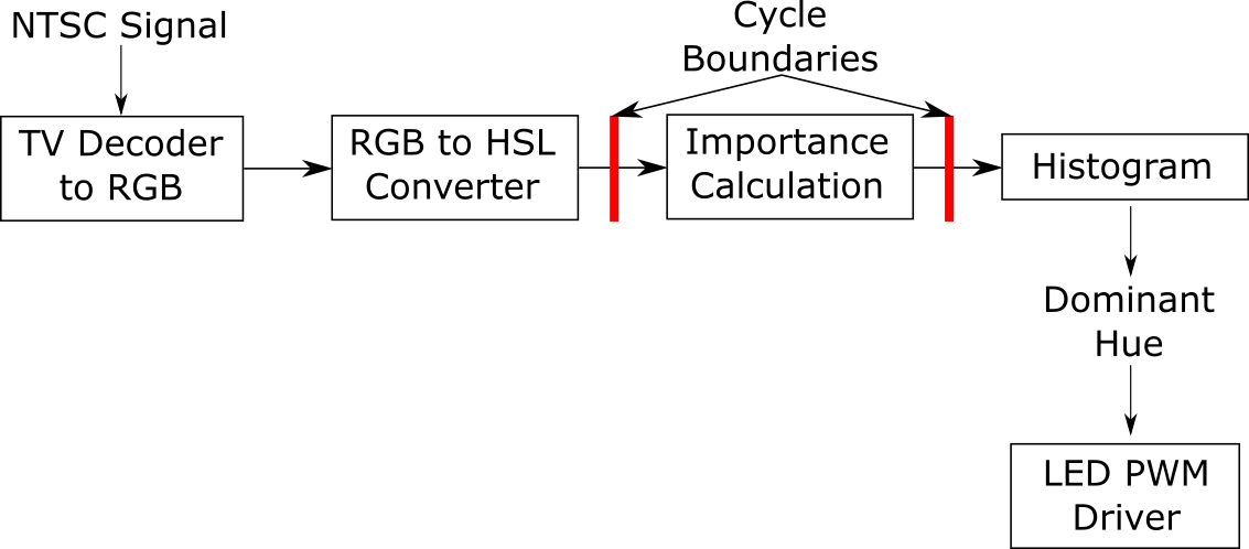
Each part of this block diagram will be explored in the Hardware Development and Testing section
Hardware/Software Tradeoffs
This entire project was written in Verilog HDL, with no software components. This was so that I could have full power over the system and its timing constraints. In order to make this system real-time, it would not be feasible to use a Nios II processor, as the latency to send the TV decoder values back and forth from the processor to do the calcuations would be longer than I want. While this meant the struggle of making all of the conversions and calculations myself, it was worth the extra effort.
One major hardware tradeoff I made was the use of look-up tables in my RGB to HSL converter. As can be seen from the equations in the math section, there are many points in which division must take place. Rather than taking the time to implement a multiple-cycle divider in fixed-point, I realized that only certain values would ever be used as divisors, and thus could be determined at compile time rather than at run time. Based on this, I created multiple look-up tables with the reciprocal of all possible divisors, which I could then use the FPGA's embedded multipliers to handle in much faster time than I could have achieved.
The other tradeoff I made was the use of pipelining in the full system. While I might have been able to push through each pixel's conversion, importance, and histogram stages in a single cycle, I did not want to risk missing any timing constraints, especially since this would be especially hard to verify at run time. To mitigate this, I pipelined the three stages.
Relevant Standards
This system requires the incoming video signal to use the NTSC video standard. For testing, the DE2-115's VGA decoder is used, which uses the standard VGA format. These standards are implemented using IP cores from Altera and example hardware modules from Terasic that are included in the DE2_115_TV example.
Patents, Copyrights, and Trademarks
The methodology used by Erwin Zwart was borrowed from heavily for this project, and his helpful information has been heavily credited where it is due in this writeup (but thanks again, just for good measure). All of this information is public, and none of it violates any intellectual property protection in his app, Hue Camera. I have simply adapted his methodology to fit my needs using my own custom hardware.
Hardware Development and Testing
To develop this project, an incremental design methology was followed, checking for feasibility at every step. This first involved creating a full MATLAB simulation of the system for a single frame, which could be tested on sample 640x480 images. The next step was to convert this to Verilog HDL, making design decisions and tradeoffs along the way. The final step was testing the system to ensure that its functionality was as expected, and was able to meet timing and correctness requirements.
MATLAB Simulator
The MATLAB simulator was created to test the methodology from Zwart's writeup. Using a set of sample images, I was able to recreate the results the Zwart was able to achieve. The simulator would first convert the image to an HSL representation, and then using fast vectorized math, quickly compute the dominant hue in the picture and output it. My first design space exploration was changing the number of hue space partitions and how closely the system could estimate the color. The sweet spot seemed to be around 16 or 32 partitions, and I determined that 16 buckets was the way to go.
During this development, I learned that Zwart's algorithm uses a weighted sum of all pixels in a given hue partition. This was easy work for MATLAB, as the intermediate steps of execution, such as the pixel values in each partition, were very easy to recall. However, in hardware, this would be an entirely different animal, requiring a lot of space and state to keep track of. Modifying my script a little bit, I experimented with hard-coding colors for each partition to output if it was the most important partition. I used the average hue for the hue partition as a heuristic, and found that for either 16 or 32 partitions, the difference in weighted sum and hard-coding was negligible enough that hard-coding was feasible as a design decision. Some examples are shown below, with the original image on the left, the weighted sum-based algorithm's result in the middle, and the hard-coded algorithm's result on the right.

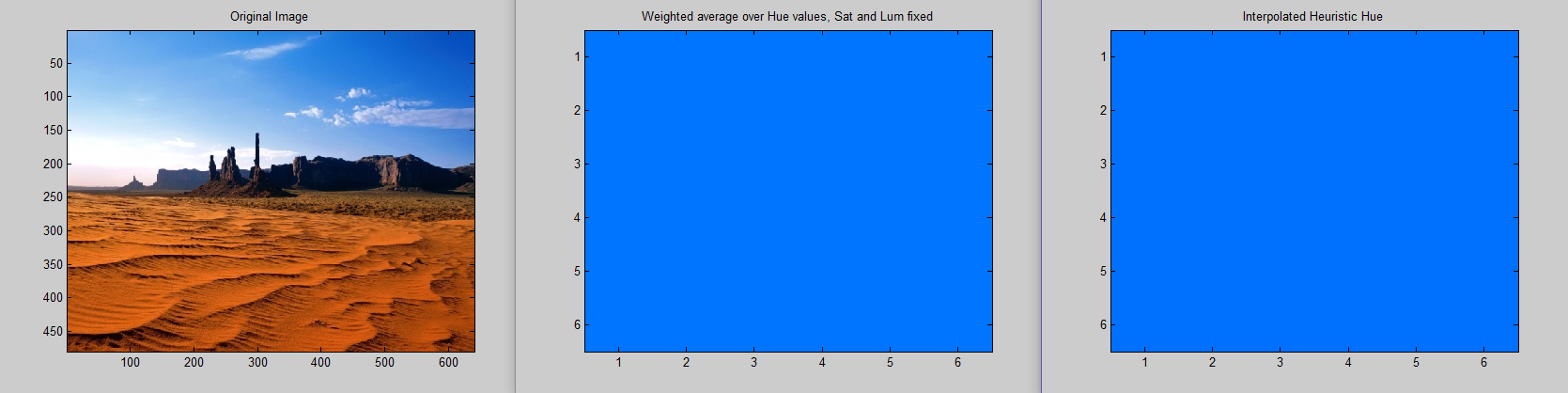
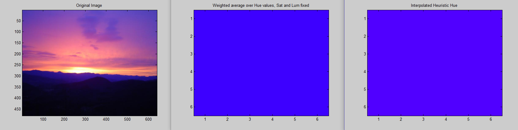
It's very difficult to see much of a difference in the first two color results. The third image, on the other hand, has a noticeable difference, but it is still close enough that the human eye could accept the hard-coded value as the overall dominant color of the screen. The MATLAB simulator let me make design decisions prior to exploring their hardware implementations, and eventually led me to use a simpler hardware than I was initially planning on.
Hardware
The hardware development was a very modular process, which I will explain piece by piece in this section.
RGB to HSL converter
In order to perform the calculations described in the math section, a few hardware modules had to be created. Firstly, a scaler module had to be created to normalize all the 8-bit inputs to 2.16 fixed point representation in [0,1]. Since there are only ever 255 values we can get into the system, we simply use a look-up table here to avoid the division. Next, there are multiple places in the calculation that rely on either the maximum or minimum RGB values, as well as their sum and difference. Using a single module, we do all of these comparisons and calculations, and send them to the necessary modules.
Once this is complete, we can move on to the calculation of the HSL components. The luminance module is trivial, involving a simple right shift of the $max+min$ value. The hue module is far more complicated, requiring different logic depending on the maximum value. To mitigate complicated calculation, a look-up table was created here as well to handle all possible values of $\frac{60}{d}$. As we can see in the equations, at some point we must multiply the difference of two terms by $\frac{60}{d}$, and possibly add a constant (either 120 or 240). Thus, it makes sense to create a look-up table and read it out, since this will only need 255 entries.
The final step in the conversion is the saturation module. The divisor here is the most complicated of all, as it can take different values based on what the $max+min$ value is. Upon closer inspection, however, we can see that this is almost like reading a look-up table forward or backward. The value of $max+min$ will only ever be in the range [0,1], or in terms of raw RGB values, [0,510] (since the maximum value here would be 255+255=510). Thus, we can always know what we will be dividing by, and depending on the luminance value, we can simply read the look-up table forward or backward. Thus, using 3 look-up tables, we can completely avoid using any division, instead leaving the work to the fast hardware multipliers. A block diagram summary of the system is shown below:

Importance Calculation
The importance calculation is a simple module, as mentioned before, taking in the saturation and luminance values, and using the equation given by $Imp = (1.0 - (abs(Lum - 0.5) * 2.0)) * Sat + 1.0)$ to calculate the relative importance of a pixel. Due to the amount of multiplication and addition that is occurring, I decided to give this calculation its own pipeline stage, just to separate it from the complexity of the RGB to HSL conversion.
Histogram
The use of a histogram is tricky in the case of this project, as we are already using fixed-point representation for all importance values, whose resolution we can't afford to lose. However, we are also summing over a 640x480 image, so we don't want to overflow a histogram partition. The situation is complicated even more by the fact that adding on the FPGA gets extremely slow as the number of bits increases. Keeping all of these factors in mind, a histogram bitwidth of 48 bits was decided upon. This gave the integer portion of the histogram far more room than it would ever need (32 bits), while also keeping the FPGAs adding at a reasonable speed and not cause a bottleneck. For the sake of safety, however, this module was treated similarly to the importance calculator, and placed in its own pipeline cycle to mitigate any adverse effect it might have on cycle time. Each time the histogram is updated, it calculates which partition currently has the largest values and outputs it. This keeps things simpler, as we don't need to know the histogram values.
LED PWM Driver
Once the best hue partition was determined by the histogram, the system had to decide what RGB values to output to the LED. Using the same methodology used in the MATLAB simulator, I determined the RGB values for the average hue of each partition with 100% saturation and 50% luminance, and placed these in a look-up table module. Once these values were determined, it was as simple as using 3 GPIOs on the DE2-115 as PWM pins. Using an 8-bit comparator and a PLL to run the PWM at 1kHz, I was able to implement a PWM controller for the R, G, and B pins, which could then go to the external hardware circuit. A block diagram summary of the system is shown below:

The look-up table for each of the 16 hue partitions can be seen below:
| Bank | 0 | 1 | 2 | 3 | 4 | 5 | 6 | 7 | 8 | 9 | 10 | 11 | 12 | 13 | 14 | 15 |
| Color |
External Hardware Circuit
The DE2-115 unfortunately does not provide the necessary current to drive an RGB LED safely. Thus, with Bruce's advice, I was able to create a circuit to take a PWM signal and command the brightness of each LED using bipolar junction transistors and a 6V external power supply. The schematic can be found in Appendix B. The PWM signal first enters an NPN BJT, which either provides high or low to its collector terminal based on whether the PWM signal is high or low. This signal feeds in to a PNP transistor, whose collector terminal is connected to the LED terminal. The 1kHz rate of the PWM is fast enough that flicker is not noticeable in the LED.
System Integration
When it finally came time to integrate everything together, all of my prior precautions paid off and everything worked right off the bat. I did not have a pure NTSC video feed from a TV station, but I used the lab camera available to me and pointed it at a video on a computer screen. When I did this, Bruce and I noticed that the automatic white balance of the camera was heavily compensating the image towards the green and blue components, and leaving red very little. At Bruce's recommendation, I implemented a feature with the switches whereby the user can tweak the "strength" of the RGB input components, either shifting left by 1, or shifting right up to 3 bits (with some compensation to dampen the sharp truncation of the right shift). Once this was implemented, the system was able to perform at full speed with the accuracy we initially expected. The controlling behavior of the system can be summarized in a very simple FSM, using the VGA vertical sync signal as a reset.

Testing
Each piece of the system was tested thoroughly at each step, ensuring full functionality and integratability before continuing to the next step.
MATLAB Simulator
The MATLAB simulator was rather simple to test, as the main test was whether a human could believe the color that the algorithm believed to be dominant. A set of four brightly-colored pictures were utilized to test the algorithm and ensure that the color was as expected. At first, the code was not vectorized, and took upwards of a minute to run one picture, but after vectorization, the algorithm sped up to take less than a second.
RGB to HSL converter
The RGB to HSL converter was easily the most heavily tested and most difficult module to get correct in this entire project. Each of the 5 separate parts of the module were independently tested using ModelSim as they were being developed, and checked against the values that we would expect from certain RGB inputs. When all components were working together, I tested the full system using a few RGB pixels, which seemed to work correctly. I made extensive use of this online HSL color picker to double check that every RGB value that I passed into the system, including the edge cases and some random values I generated.
Importance Calculation and Histogram
The importance calculation and histogram were trivially easy to test using ModelSim. The importance calculation could quickly be verified against known inputs using a quick C program I wrote. Likewise, the histogram could operate with different inputs for a few cycles and verified that all values entered their respective partitions correctly.
Partial Integration
After the previous components were independently tested, I partially integrated them to test out the pipelining I planned. When I did this, I found that things seemed to work as planned, as full pipelining was not a difficult feat, and the reset logic was relatively simple to implement. However, a few test pixels were not enough to be confident in this module's ability to handle the runtime load of a full 640x480 image. To fully test this, I used MATLAB to output a Verilog file to push all pixels from my test images through the ModelSim test bench. These tests took upwards of 10 minutes per picture, but miraculously, all of them output the correct hue space partition on the first try, showing that I had successfully created a hardware module to clone the MATLAB simulator's abilities.
LED PWM Driver and External Circuit
The LED PWM Driver was very simple to test, first using ModelSim to check its periodicity, and then an oscilloscope to ensure the correct frequency was being generated. The external circuit was initially tested using a fixed power source to ensure that a high voltage could turn on all three colors, and that a low voltage would turn all of them off. Thus, with a fast enough PWM, I could be sure that I would see the intensity I was expecting.
System Testing
When everything was integrated together, I was able to test the entire system using a camera pointed at a video. As mentioned in the hardware design section, the camera's white balance negatively affected the results until the compensation for each component was added, but after this, I was able to test it on a variety of internet videos and real-life objects to ensure that the system was working correctly. The realtime response of the system and the correct results were enough to convince me that my project worked as planned, at long last.
Results
Execution Speed
The system operates in effectively real time, keeping up with the speed of the FPGA's TV decoder and conversions to RGB. There is no noticeable lag, and the system's colors all seem reasonable for the objects or pictures they are pointed at. The RGB LED I used is very bright and the overall color is sometimes hard to discern from up close, but a thin layer of paper helps to mitigate this issue. All third parties who witnessed this system in operation seemed impressed by its execution speed.
Accuracy
The accuracy of this system was remarkably good, though different applications of this algorithm would possibly need higher accuracy. For example, 16 partitions in hue space might be enough for a theft deterrent device in an unoccupied house, but if this system was to provide live ambient light for a TV screen, more partitions might be needed, such as 32 or 64. This would not be difficult to implement, and should be easily doable by a DE2-115 FPGA.
The compensation for the RGB inputs to the system are not entirely perfect and could probably use a little bit of tuning, especially in the case of scaling a component down. When I first tried implementing this, I scaled the green component right by one, which effectively got rid of its effect on the system entirely. To mitigate this, I added a constant value back in to the component to make sure it wasn't entirely erased.
Demo Video
Sadly, it is not easy to capture the true behavior of this system using static pictures, due to white balance and automatic image adjustment in most cameras, so here's a moving picture to compensate. A demonstration of the functional system can be seen in the video below.
Conclusions
Overall, I am extremely happy with the way this project turned out. I was able to accomplish all of the goals I set for myself, and I had remarkably good fortune while coding in Verilog. The algorithm from Erwin Zwart works extremely well, and is extremely well fit for an FPGA and real time system. At no point in this project did I ever question whether I should completely ditch the algorithm. The system is not entirely accurate, due to the use of only 16 hue space partitions, but this is completely sufficient for demonstration and proving the concept. A smoother space of colors would be easy to implement, and it would be interesting to compare the two.
All of the analysis functions of the system use my custom Verilog modules, and are very optimized. I'm also very happy that I was able to write an accurate, fast RGB to HSL converter which can be used by future generations of ECE5760 students. Altera and Terasic were instrumental in providing sample code for interfacing with the TV decoder, which I am very thankful for, as it doesn't look like something I could have accomplished myself without help.
This was a fun challenge for me, and was a great way to finish off this course and my time at Cornell. This project used many skills I have learned throughout the semester, especially in the way of incremental design and verification. It is certainly a testament to this course that I was able to implement most of this project without major design bugs and that my integrations worked almost immediately each time. I hope this project can be of use to future ECE5760 students.
Appendices
Appendix A: Code Listings
Full Project- Full project code, based on Terasic DE2-115 TV example
MATLAB Simulator- Used to test algorithm and design space
PWM Driver- A simple PWM driver for the DE2-115, controlled by the onboard switches
RGB to HSL converter- The independent RGB to HSL converter used in this project in a Quartus/Modelsim Project for easy use by others
Floating/Fixed Point Conversion Program- A useful C program to convert from floating point to a specified fixed point representation, based on the specified number of decimal bits
Appendix B: External Hardware Schematics
The external circuit to drive the LED with an external power supply and PWM signal. Three of these were used, once for each component of the RGB LED

References
This is How Hue Camera’s Algorithm Works- Erwin Zwart's amazing writeup about color that made this project possible
Reconfigurable Hardware Acceleration of RGB to HSL Converter- The basis for my RGB to HSL converter
Acknowledgements
I would like to thank Dr. Bruce Land for being so supportive of me throughout this year, and especially in this course. Coming in as a simultaneous TA and student to ECE 5760 was rather intimidating, but somehow, with your help, I made it through without crashing and burning. For all the times I stopped by your office with one issue or another, you were always patient, calming, and I always walked out enlightened. Many thanks to the ECE 5760 class for bearing with me learning the concepts while also trying to help you. I hope I was a good resource to all of you, and somewhat helpful in lab.