Head Related Transfer Function Explorer
Justin Cray (jgc232), Mihir Marathe (mmm389), and Junpeng Wang (jw2299)
Introduction
The purpose of this final project is to implement an FPGA based head related transfer function (HRTF) system. The goal of the HRTF is sound spatialization, where a sound is played in a way such that a person wearing headphones will think the sound is coming from a location in space around their head. In practice the mock spacalization is acheived through filtering the left and right outputs of the music separately, through different FIR filters. These filters are based on filters determined by researchers at UC David (see references.)
Our project utilizes HRTFs in two ways. First, the system allows a user to identify the HRTF which corresponds to their own personal head parameters. While every human has a different HRTF, we can identify a similar enough HRTF such that the user should observe very similar effects to the fully accurate HRTFs. We accomplish this through identifying similar HRTFs and having users test and validate the functions. The second functionality is playing three different sample sounds. Once we've identified a sufficent HRTF, we can emulate spacial sound using convolution and play the sound out of the audio codec of the FPGA.
High Level Design
The FPGA can be considered a soundcard in our system. The HPS is preload with the FPGA fabric with HRIR transfer function and one discrete sample of sound input at each full cycle of the FPGA state machine. The bulk of information is transferred with a shared SRAM that contains 402 32-bit entries. Once the information is ready, the FPGA does the convolution and outputs the sound directly into the audio FIFO. Beside the audio processing and output, everything else, including VGA user interface and HRIR down-selection, are done on the HPS part of the system.
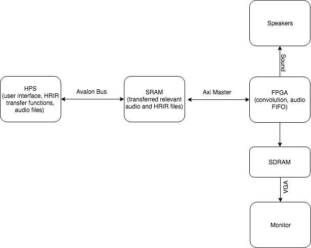 Figure 1: Block Diagram of Overall Design
Hardware
Math Considerations & Convolution Logic
The HRIR transfer data for each elevation, azimuth and subject combination has 200 data points, precise to 1e-6. Each sample of the audio input are normalized so that each has amplitude less than 1. Therefore, the largest amplitude output of a convoluted sample is 200. Given the amplitude and precision requirement, we decided to use 10.17 fixed point scheme in the convolution calculation.
The convolution is done by a long chain of datapath, containing 200 27-bit datapath registers for each of the left and right audio channel. S stand for time-domain sound input sample, and H stand for HRIR data.
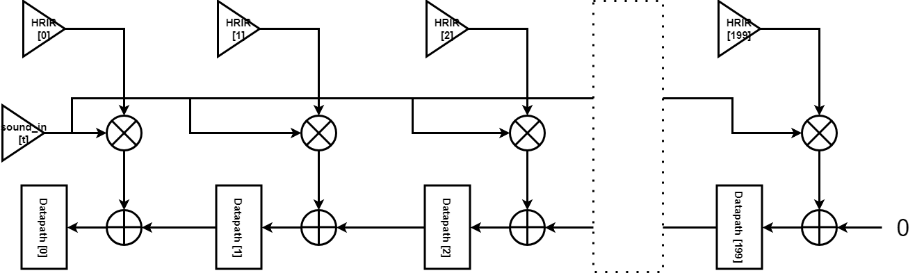 Figure 2: FPGA Convolution Datapath
Looking at the first 3 datapath registers:
| t |
Datapath[0] (Output) |
Datapath[1] |
Datapath[2] |
| 0 |
S[0]H[0] |
S[0]H[1] |
S[0]H[2] |
| 1 |
S[0]H[1] + S[1]H[0] |
S[0]H[2] + S[1]H[1] |
S[0]H[3] + S[1]H[2] |
| 2 |
S[0]H[2] + S[1]H[1] +S[2]H[0] |
S[0]H[3] + S[1]H[2] + S[2]H[1] |
S[0]H[4] + S[1]H[3] + S[2]H[2] |
| 3 |
S[0]H[3] + S[1]H[2] + S[2]H[1] + S[3]H[0] |
S[0]H[4] + S[1]H[3] + S[2]H[2] + S[3]H[1] |
S[0]H[5] + S[1]H[4] + S[2]H[3] + S[3]H[2] |
Table 1: FPGA Convolution Datapath over Discrete Time
The table can continue with infinite entries of audio samples and do the discrete time convolution.
However, an important limitation we has is that, the FPGA fabric has only 78 DSP units with 27x27 multiplier. Therefore, we are doing the convolution of each of the left/right channel in 4 clock cycles instead of one. We start operating on Datapath[150] to Datapath[199], while storing the value in Datapath[150] in a Carry register. Then in the next clock cycle, we operate on Datapath[100] to Datapath[149], and feed the carry register to the adder that outputs to Datapath[149]. In this way, we spend 8 clock cycles to convolute audio output for both the left and right audio channel.
Audio FIFO
The Audio FIFO FSM we used was taken from the Audio code example available on Professor Bruce Land’s website. The image below shows the audio write FSM states and transitions. The only modifications we had to apply to the original FSM was to identify which state was the one in which we could do our audio sample synthesis, prior to loading it into the FIFO L/R buffers. This was identified to be the state that followed the one that cleared the Audio FIFO and where the FIFO had space available. The state for the standalone of audio FIFO can be described as follows:
State 1: Sets up the available FIFO address and the reads the available space in the FIFO
State 2: Waits for the FIFO read ack and then moves to State 3
State 3: Entered when room is available in FIFO, and then computes next synthesis sample. Only shift to State 4 if space is available, otherwise go to State 1. Write to Left FIFO.
State 4: Waits for Left FIFO Acknowledgement, then go to State 5.
State 5: Writes to the Right FIFO, then shift to State 6.
State 6: Waits for Right FIFO write ack from the Bus Master, then moves to State 1.
SRAM Shared Memory
The bulk of information, containing the HRIR function, sound input amplitude, and status flag, is transferred with a shared SRAM between HPS and FPGA that contains 402 32-bit entries. The memory space is mapped as follows:
| Offset from Memory Base Address |
Content |
| 0 ~ 199 |
HRIR for left audio channel |
| 200 ~ 399 |
HRIR for right audio channel |
| 400 |
Sound input sample amplitude |
| 401 |
Status flag |
Table 2: Index Legend for Shared SRAM
The HRIR and sound input all have 10.17 fixed point format. The status flag can contain an integer value from 0, 1 or 2. FPGA writes a 0 to the status address when it finishes loading the audio FIFO, indicating the data is processed and FPGA is ready for new input. HPS writes a 2 to the status address if HPS has updated the shared SRAM with new HRIR and a new sample of audio input. HPS writes a 1 to the status address if HPS has updated the shared SRAM with a new sample of audio input while keeping the HRIR the same, to save clock cycles on the FPGA.
System Architecture
The QSYS layout containing all the sub-systems are as follows:
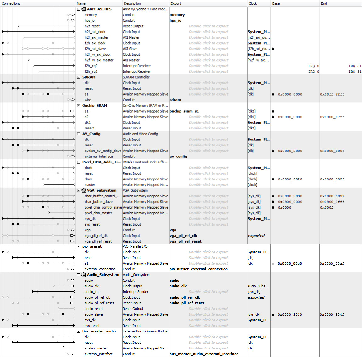 Figure 3: QSYS Configuration
The VGA subsystem is driven directly by the HPS, and memory mapped in SDRAM. The SRAM for memory shared is configured as 2-port SRAM with one port tied to the HPS axi master and the other port exported to the FPGA fabric. Note that there is a parallel I/O port between HPS and FPGA for resetting the system.
System State Diagram
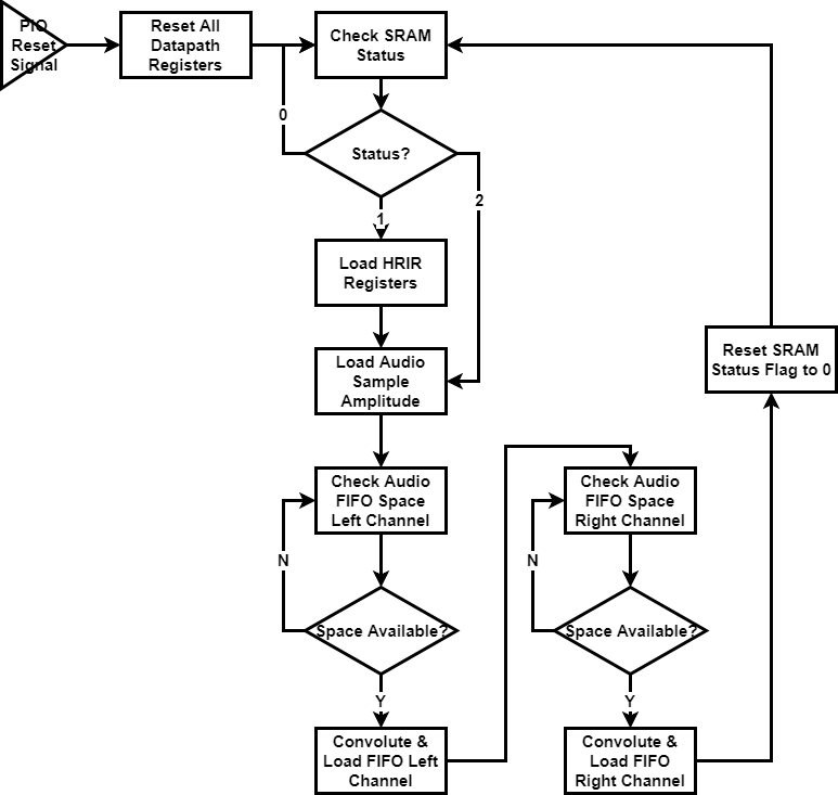 Figure 4: System State Diagram
The FPGA actually has over 1000 states to keep track of memory read and convolution calculation. The states can be categorized as follows:
| State Number |
Function |
Note |
| 0 ~ 8 |
Load Audio FIFO & Reset Status |
Write 0 to status flag and go to state 96 after |
| 10 ~ 17 |
Convolution |
Explained in “Convolution Logic” Section |
| 30 ~ 32 |
Load sound input from SRAM |
3 clock cycles to read from SRAM, go to state 0 after |
| 96 ~ 98 |
Load status flag from SRAM |
Go to state 99 after |
| 99 |
Direct to new state based on status flag |
0 - go back to 96 and keep checking status
1 - go to state 30 and load new sound input
2 - go to state 100 and load new HRIR
|
| 100 ~ 1299 |
Load HRIR from SRAM |
3 clock cycles to read each entry from SRAM, 400 entry in total. Goes to state 30 to load sound input after |
Table 3: All States in FPGA
Software
System Overview
The HPS side code was mostly used for the top level user interface, VGA display generation and control, as well as the down-selection procedure implementation. While not computationally heavy, the C code was mostly a balancing of timing constraints of the UI as well as the graphics display setup on the VGA. In addition to the UI control, the HPS was also responsible for taking advantage of the Linux file system such that the processing of the large two-dimensional HRIR arrays for each of the 45 subjects was minimal in terms of processing time.
Memory Address Acquisition
A feature of note in this system design was that since both the HPS and FPGA required access to some of the same datasets, and the fact that the Hardware had to integrate both VGA forwarding (in the FPGA) as well as setting up the Audio subsystem, the on-chip SRAM was chosen as the shared memory cell between the HPS and FPGA. As described in the Hardware Section, the s2 port of the on-chip SRAM is tied to the HPS via the Avalon bus. The memory address offsets used in the SRAM are from 0 - 402 for the full set of share data. The acquisition of this base address occurs in the main.c file via the mmap() function which maps the expected base addresses and offsets to a virtual memory space which is then available to the HPS for data transfer. During initial testing and setup of the shared memory, we had to an incorrect input to the mmap() function using the FPGA On Chip Memory span whereas we actually required the SRAM memory address span for a correct mapping. Once this issue was corrected, we were successfully able to send 200 element arrays to the SRAM and successfully hear sounds at various spatial locations.
HRIR Data Access and Parsing
The Head related impulse responses (HRIRs) for each subject, post compression into a 2 dimensional array, are stored in a folder called hrir_headers in the top level folder as the main executable C file. Initial attempts to include these HRIR header files consisted of include statements in C, which led to compiler errors, as the compiler ran out of virtual memory when linking the various objects (header files). Our solution to this issue was to utilize the linux file system and the C file IO standard library functions to parse the header files as strings and to convert them into viable float arrays which could be accessed within the main code. The method of implementing this essentially required that all of the header files be formatted the same way, with each row of the 1250 x 200 HRIR array being placed on a new line with a new line character at the end of each line. The hrir_lr_assign() function essentially opens up the desired subject’s .h file, identifies the correct row of the file which has the desired HRIR row, and uses the fgets() function to obtain a character array of the desired row. Following that, using the strtof() stdlib function, the function iterates through the character array and parses each set of numbers delimited by a white space into a float value, which is then added to a globally defined array for use in the read thread.
HRIR Down-Selection Algorithm Implementation
The down-selection algorithm, per the pre-processing methodology, was decided to be a 1-tier exploration of nearest neighbors of testing subjects. A two dimensional array of 45 x 6 elements is loaded into a global variable, where each row is that indexed subject’s associated nearest neighbors (per a threshold). The down-selection process plays 4 different elevation/azimuth pairs, and the user identifies whether or not those 4 audibly spatially located positions match the displayed locations on the VGA. The metric is no match, full match, or a ‘close’ match, which is highly subjective and user specific.
If, during the down-selection process, a subject is deemed to be inaccurate enough, the algorithm either randomly gets a new subject for testing from the subjects list, or finds the next nearest neighbor of the initial testing subject. In both possible paths, the newly returned subject is tested to ensure that it has not been already tested, and if it has, the new-subject finding is repeated until a new untested subject is found, or the program quits. Whether or not a new random subject or a new neighboring subject is used is dependent on how many of the testing elevation/azimuth pairs are evaluated to be close or far away. If more than 1 pair is close, a nearest neighbor search is triggered, whereas if more than 1 pair is ‘far away’, or has no VGA match, a new random subject search is triggered. The four testing pairs we used were the following (elevation, azimthuth (in degrees)): (45,-35),(0,35),(225,35), and (0,-35). These are very easily customizable and the visual interface will adapt accordingly.
The implementation of the down-selection process was a very smooth process and had no errors during the implementation. This process is highly user-dependent, where some users have identified the correct HRIR within two iterations, whereas others have never found them. Also, as with any search algorithm, the system is highly initial condition dependent.
HRIR Testing Methodology
The HRIR selected during the down-selection process is tested in the read thread’s test mode by allowing the user to select an audio source of their choosing, from a preset list, where each sound source is 221184 samples long. A preset list of 12 azimuths is already loaded in a global array, and at each azimuth, 1/12th of the samples available are iteratively loaded into the soundcard. This is sequentially processed until the sound source sounds like it is being swept around the user’s ears at an elevation of 0 degrees (this elevation is also easily customizable). The ideal result of this is that the sound source is seamlessly ‘moved’ around the person in a circle, and if the HRIR is best-matched to the user, then the sweep is audibly identifiable by the user for any most elevations and all azimuths.
Thread Structure
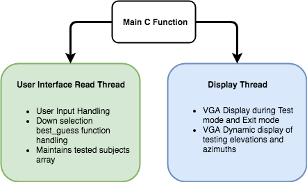 Figure 5: HPS Side Threaded Structure
Top_Level.c
- Memory base address acquisition
- Clear VGA screen
- Setup POSIX Multithreaded setup (per ECE 5760 templates)
thread_read
- Asks for user input, and sets up initial conditions
- Runs Down-selection algorithm and checks for tested subjects
- Identifies best match subject
thread_display
- In down-selection mode, displays static elevation and azimuth perspectives, and dynamic changing locations of elevation and azimuth when playing test points
- In test mode, just displays test mode message
- In exit mode, just displays exit mode message
User Interface Top-Level
The top-level performance of the user interface is that it operates in one of three modes:
- Down-Selection of HRIR Subject Match
- Testing of HRIR Subject Match
- Exit Mode
During the top-level execution of the program, the user is offered the opportunity to enter any of the modes above, and the option is presented once again at the end of a mode’s execution. Each of the modes operate as described above. The Exit mode essentially freezes the VGA display on the exit screen and causes the c code to quit (using the exit(0) function).
The following images are examples of the VGA display during the three modes of operation.
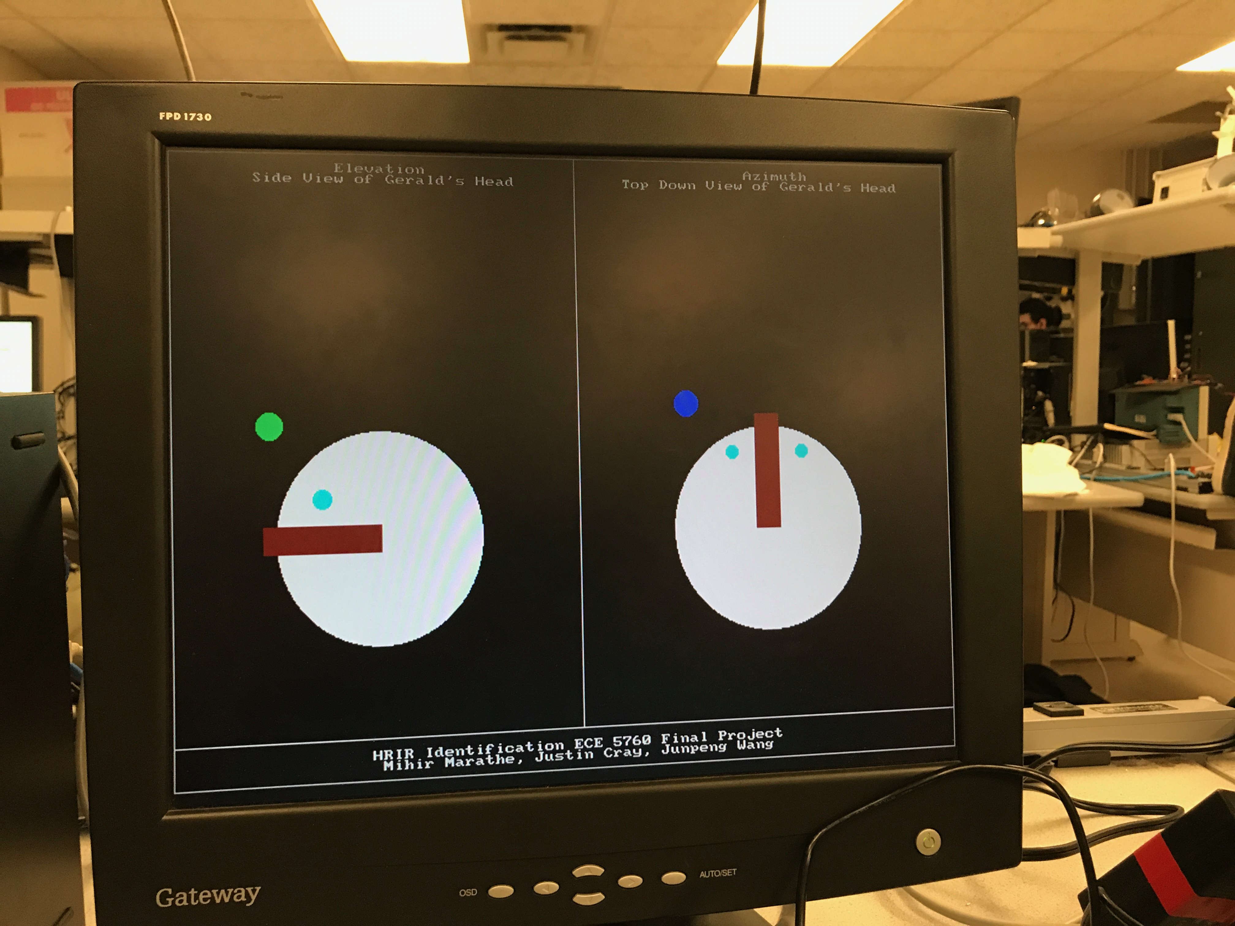 Figure 6: Demonstrating Down-Selection Testing Process with Gerald The Test Head
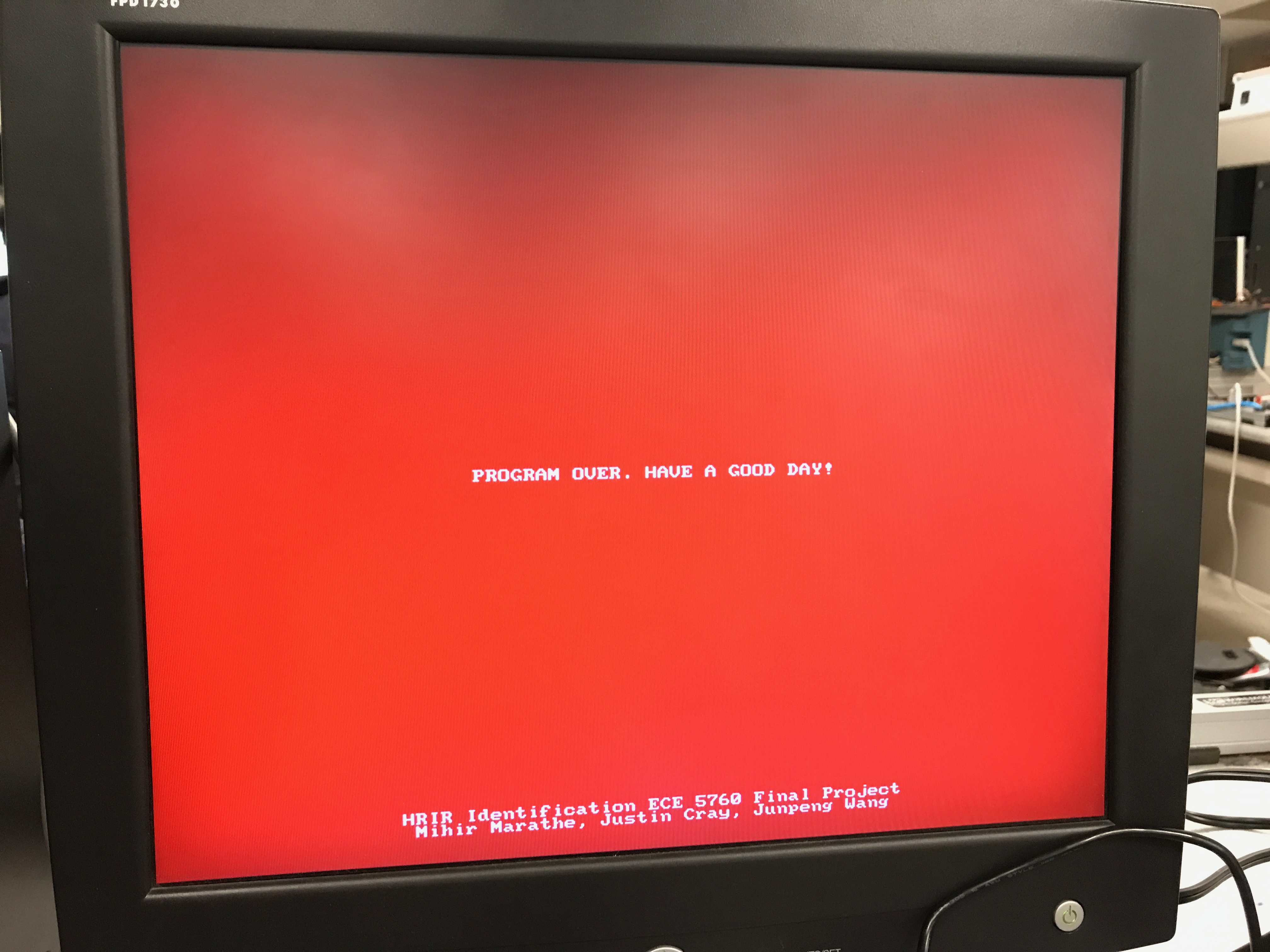 Figure 7: Exit Mode
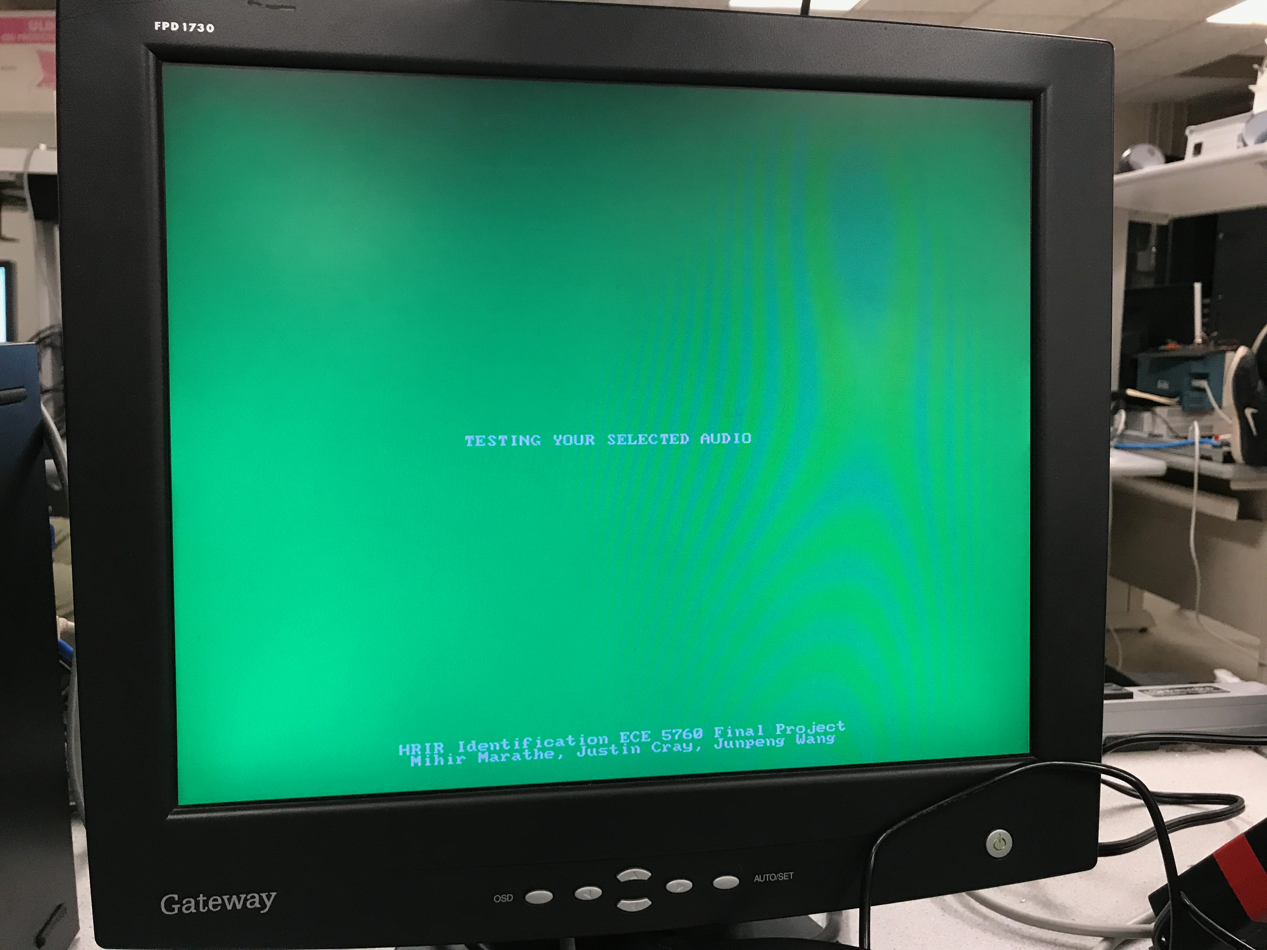 Figure 8: Test Mode
Results of Design
To test the standalone convolutor unit, we set up a testbench in ModelSim. The sound input amplitude is set to a constant one, and the left HRIR is set as an array stepping up from 0 to 199, and right HRIR is set as an array stepping down from 199 to 0. The convolution result in analog waveform is shown below, which met the expected math outcome:
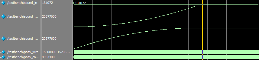 Figure 9: ModelSim Test for the Convolutor/center>
Here is the waveform of the the left channel (1 on scope) and the right channel (2 on scope). The HRIR is set to have elevation and azimuth at 0 and 0 respectively, so the left and right channel has similar amplitude. However, one can still identify some minor difference between the channels due to some minor asymmetries in human body.
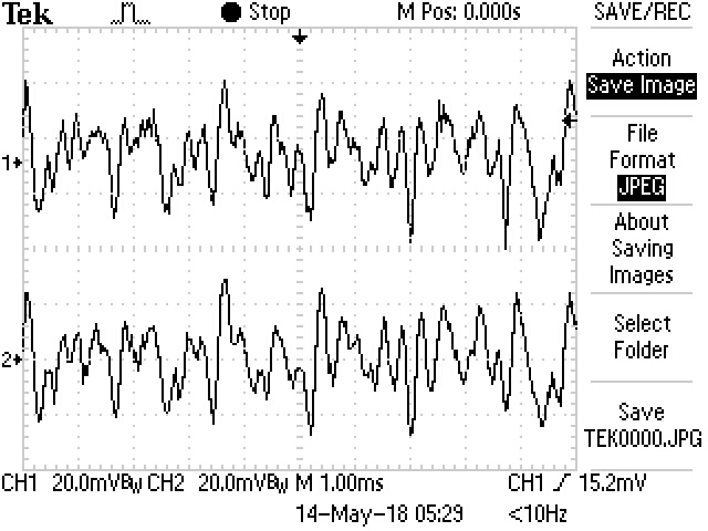 Figure 10: Audio Output for Subject 003 at 0 Elevation and 0 Azimuth>
Here is the waveform for the same subject, but with azimuth changed to -45 degrees, so that the sound should source 45 degree to the left from the subject. One can see that both the amplitude and shape of the waveform for left and right channel are very different:
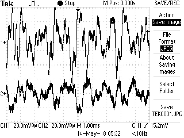 Figure 11: Audio Output for Subject 003 at 0 Elevation and -45 Azimuth
During the final testing of the system itself, the only user interface side feature that did not exactly perform as initially expected was the test mode of the user interface. There are distinct ‘clicks’ heard when in test mode and sweeping the selected audio source with 12 different azimuth positions located in a circle around the human test subject. The initial idea was to have a smooth continuous sound, which is almost achieved. The ‘clicks’ are a result of there being a few elements of the audio FIFO buffer being randomly populated due to there being some memory transfer latency between successive azimuth/elevation transfer functions being transferred to the on-chip SRAM over the Avalon Bus. The test mode still proves the success or lack thereof of the down-selected HRIR subject however, and so the slight performance discrepancy is an easily solved HPS side problem (the solution would probably require another thread to preempt HRIR to on-chip SRAM transfer while the previous location sound is playing).
The Final result of the HPS C code being integrated into the Soundcard setup is essentially a functioning endpoint demonstration. The following link shows the main functionality of the integration:
HRTF Down-Selection Demonstration
The image below shows the full system testing setup.
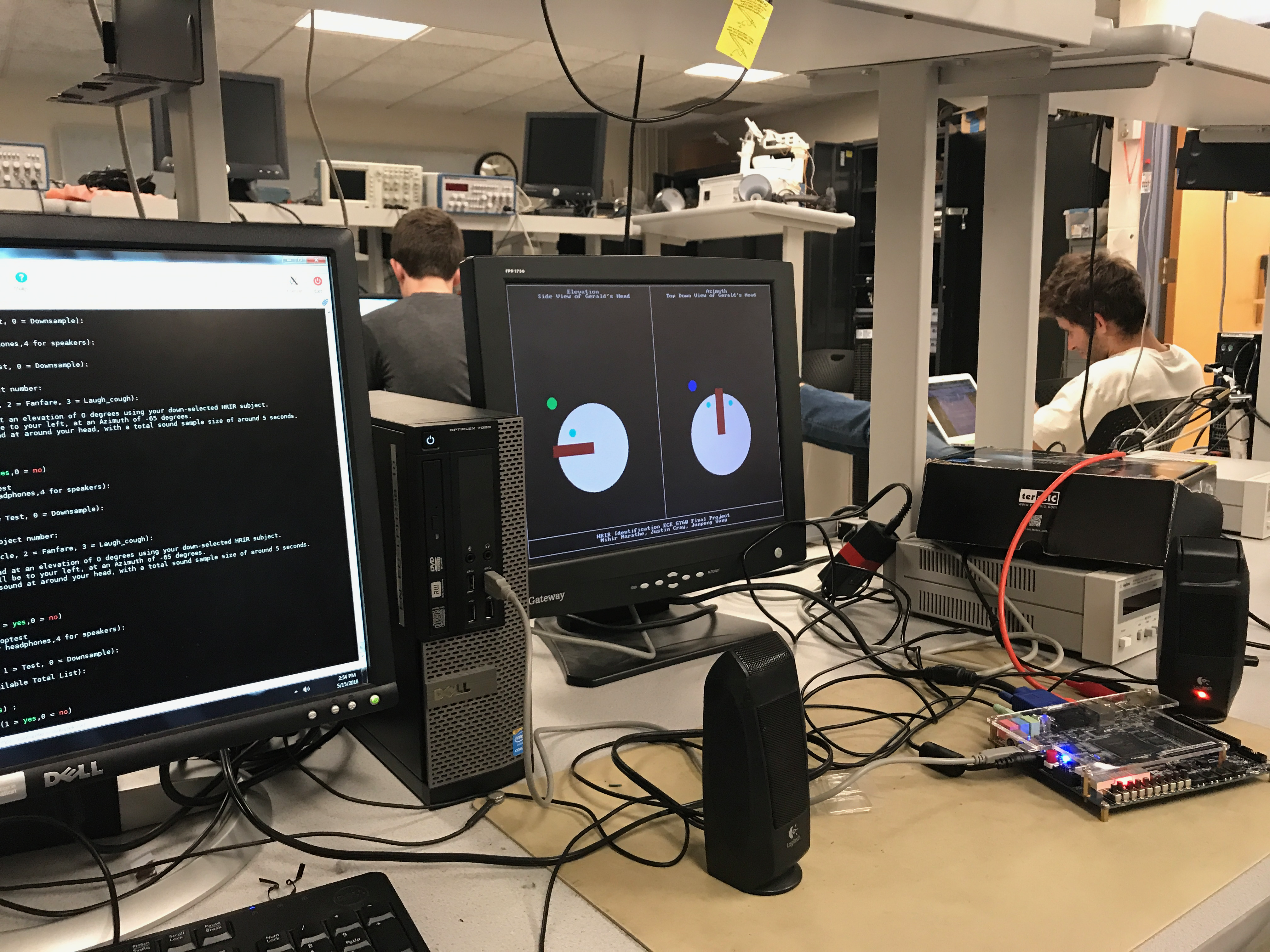 Figure 12: System Testing Setup
Conclusion
Improvements
Overall, we were pleased with the final outcome of our project. If we were to make improvements to the design in the future, we would implement a more sophisticated down-selection algorithim to match users with possible pairs. We would also likely adjust the test points to make sure they are more thorough in their analysis. We would also add some smoothing to the sound outputted in test mode as well as add additional sounds for the user to try. We would also like to render more sophisticated graphics and verbose instructions.
Intellectual Property Considerations
We did not use anyone else’s design for this project. We did not have to sign any non-disclosure forms for any part of the project.
We would like to acknowledge the Regents of the University of California and the CPIC for collating the aforementioned database, and for permitting use of it for educational purposes.
Standards
All applicable standards (such as IEEE) were adhered to.
Legal Considerations
There were no other legal considerations to make.