Michael Henning (mch258)
Max Rademacher (mtr73)
Jonathan Plattner (jsp263)
ECE 5760 Final Project:
Interactive Mandelbrot Viewer
Introduction
The internet contains many videos. While these videos come in many shapes and sizes, there is one category of them which entertains more than any other; one category that is truly the pinnacle of western culture: mandelbrot set zoom videos.
Yes, that's right. Youtube is full of videos zooming in on the mandelbrot set. As majestic as all of these zooms are, after watching them for every day of our lives so far, we eventually came to question their dominance. Wouldn't it be better to be able to control what part of the mandelbrot set we were viewing? Wouldn't it be nice to have control over our own destiny?
We set out on the most important journey of our lives. We spent many moons, in lab, seeking a better way to view the mandelbrot set. Finally, we emerged with a solution.
And now, you can benefit from the fruit of our labor with the ECE 5760 Real-TIme Mandelbrot Set RendererTM! This amazing improvement on former mandelbrot rendering technology uses an FPGA to accelerate rendering to incredible speeds. This, in combination with custom-developed mandelbrot viewing software, allows interactive exploration of the mandelbrot set to a degree that humankind has never seen before.
Design and Testing Methods
High Level Design
The mandelbrot set is the set of points in the complex plane that converge in the following series, where c is the original point in the complex plane.

It has been proven that when the magnitude of z is larger than 2, the series will diverge. Thus, the set is computed by iterating through the z series of each pixel and stopping when either the divergence criterion is met, or when some iteration limit is met. If the iteration limit is met, the pixel is considered to be in the set.
Our goal with this system was to allow for real-time exploration of the mandelbrot set at relatively deep zoom levels, and a number of design decisions were made in service of this goal. We realized that in order to achieve deep zoom levels, we needed the ability to cache the images of the mandelbrot set that we generate, because the calculations of deep zooms cannot be done at an interactive rate of 60 fps. We therefore have our solvers output tiles, which are 64x64 pixel images of the mandelbrot set that are generated at discrete locations and zoom levels and form the basic unit of caching and parallelism in our design.
At a high level, the system works as follows: The user interacts with a program running on a standard desktop or laptop computer, which allows them to control the viewport of what parts of the mandelbrot set they are exploring. This program then sends requests for tiles over the network to a tile server, which is running on linux on a DE1-Soc board. The DE1-Soc has an integrated FPGA, which is then used to accelerate solving the tiles. Once tiles are solved, the tile server collects the results and sends them back to the user’s computer, which displays the tiles on the screen.
In order to support deep zooms of the mandelbrot set, we had to make sure that none of the components of our design had significant limitations on the precision of the numbers used. This means that the viewer program had to maintain viewport coordinates as arbitrary precision numbers, the request interfaces had to support variable length requests, and the solvers had to be written with arbitrary precision arithmetic support.
Hardware
Because one of the main goals of the project was to be able to zoom in infinitely, we needed to be able to compute the z series with arbitrary precision. We chose to represent the arbitrary precision numbers in 27 bit chunks called limbs. The first limb or the number is the integral part and all of the following limbs make up the decimal part. Addition in this format is fairly simple - add all of the corresponding limbs of the two numbers together, keeping track of a carry. Multiplication, however, is a harder problem. The algorithm we chose is the simplest (grade school) algorithm and has an O(n2) running time. Take each pair of limbs in the two numbers and multiply them together. Then add the result into the appropriate limb in the result and propagate the carry. The index of that limb is computed by adding the indices of the multiplicand limbs, where the most significant limb is at index zero.
A single solver on the FPGA is can solve one tile at a time. It does so by solving each pixel in series and then moving to the next pixel in the tile and solving it. The pixel is computed by solving an iteration of the z series, checking for divergence, and then repeating if it did not diverge. To compute a single iteration of the series, the solver evaluates both the real and imaginary components of zn+1 one limb at a time. The formulas of zreal and zimag are given as follows.


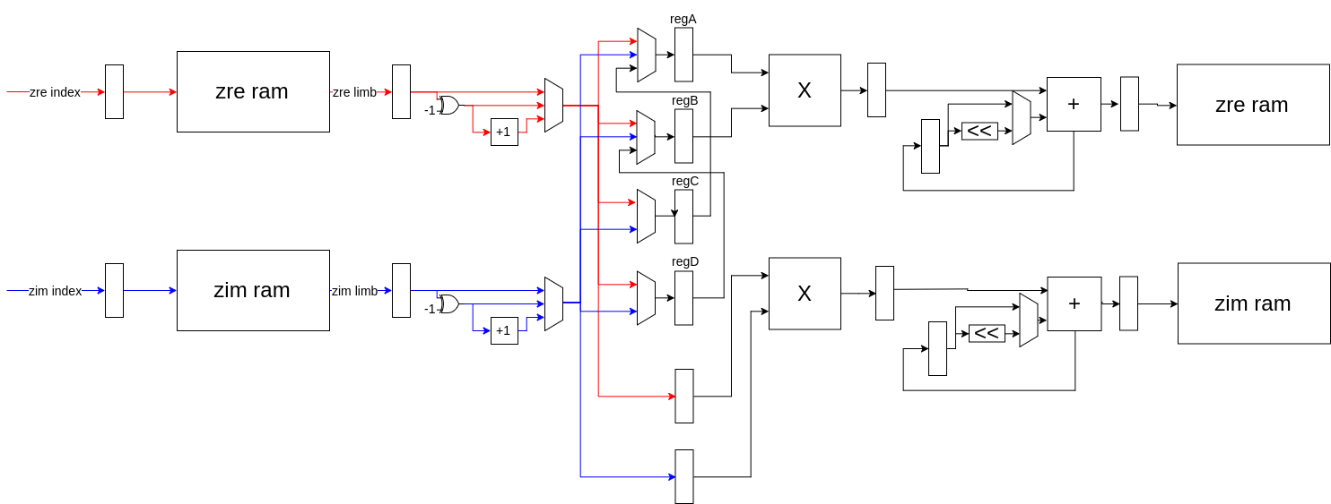
To compute a limb of zn+1, the solver iterates through all of the pairs of limbs in zn whose indices sum to the index of the limb currently being computed. For each pair of limbs, it first loads them from the two M10K blocks dedicated to storing the real and imaginary components of z. It also loads the real and imaginary limbs of c from two different M10K blocks. The components of z are then multiplied together to compute the products: zrealzimag, z2real, and z2imag. The zrealzimag product is computed once a cycle with a DSP multiplier. The squared products require multiple limbs from the same number, but we can only load one limb per cycle. Thus, the second multiplier alternates computing z2real and z2imag while the values for the product not being computed are queued up. As the three products are computed, they are folded into an accumulator which keeps track of the values for the components of zn+1 currently being calculated. For the real component, this is done by adding in either the result of the squaring multiplier, or by adding in its negation, depending on whether the multiplier had just computed the square of the real or imaginary limbs. For the imaginary component, folding into the accumulator is done by left-shifting the result of the other multiplier by one to multiply by two and then adding into the accumulator. Once the two components of the limbs of zn+1 are fully computed, the values of the accumulators are saved into the same M10K blocks that originally stored the components of zn. The accumulators are reset and initialized with the carry from the previous limb (this is done by signed right-shifting the previous accumulator value) plus the value of the appropriate c limb.
The solver was designed with a pipeline architecture in order to reduce the critical path. It consists of six stages. First, the control stage (C) is a large state machine which determines all of the necessary control signals needed to get the rest of the solver to perform the computation. Then the read stage (R) reads the appropriate real and imaginary limbs from z and c from the four M10K blocks used to store them. Next, the absolute value stage (A) ensures that numbers being sent to the multipliers are positive. This is necessary because the multiplication algorithm does not work if any of the multiplicands are negative. The multiplication stage (M) consists of the two multipliers - one which computes zrealzimag and another that alternates squaring the components. In the execute stage (X), the products are folded into the accumulators. Finally, the limbs of zn+1 are written back into ram in the write stage (W).
The control stage keeps track of an iteration count and terminates this process, so the solver can move to the next pixel, if the iteration limit is reach or if the series diverges. Divergence is computed by keeping a divergence accumulator which stores the value of z2real + z2imag. If the value of this accumulator is larger than 4 when the last limb is done being calculated, then the series has diverged and the solver can move to the next pixel.
Software
The software for this project was split into the server- and client-side code. The server runs on the HPS does the work of solving the mandelbrot equation and sending the resulting iteration data to the client. The client runs on a laptop and is responsible for coloring and rendering iteration data, as well as handling user input. This separation allowed us to move the computational load of rendering from the HPS/FPGA to a separate laptop, improving solver performance and also allowing higher resolutions (we used 1600x900, but 1080p is probably possible). The client can also connect to multiple servers, so running two or more FPGA solvers allows for more performance improvements.
The mandelbrot solver from lab 3 would solve the mandelbrot equation for every pixel, every frame. This was inefficient because often each pixel is regenerated hundreds of times when it could instead have been cached and reused. One of the primary optimizations we implemented was storing this generated data and reusing it each frame. Rather than solving a single pixel, the FPGA solves one “tile” at a time, where a tile is a 64x64 square of pixels. This tile data was then stored in a tile cache, and then tiles were rendered to the screen multiple times without being recomputed.
A tile is uniquely identified by a 4-tuple of integers (x, y, z, i). The i value of a tile specifies the iteration limit. The z value represents the zoom level of the tile, where tiles with z=0 have a width and height of 1. Increasing z by 1 corresponds to decreasing tile size by a factor of 2. The values x and y specify a tile’s location, where a tile with x=0, y=0 has its bottom left corner at the point (0, 0). A tile with x=1, y=0 is one tile length to the right of (0, 0). Thus, the point in space specified by x and y is dependent on the value of z. As z increases by 1, x and y will increase by a factor of 2. Because of this, x and y were represented as multiple-precision integers because they overflow a 64-bit long integer when z is greater than about 64. These 4 values are stored in the TileHeader class.
The renderer has a viewport that is defined by a complex origin and a complex screen size. With this information the renderer can generate a set of TileHeaders that will span the viewport. The renderer sorts these TileHeaders based on a priority function, so that the tiles in the center of the viewport are of high priority and are generated first. In order of priority, each TileHeader is serialized and sent to the server as a tile request.
The server receives tile requests from the client and deserializes them into TileHeaders. It then converts each TileHeader into the format used by the FPGA. The x and y values, which are multiple-precision integers, are converted into a format understood by the FPGA, multiple-precision values with 27 bit limbs. This data (plus the iteration limit) is sent to the FPGA, which then solves the tile and writes it back into HPS memory. Once the server has a solved tile, it sends the serialized data back to the client over ethernet.
When the client receives a tile, it stores it in a tile cache. When the renderer requests the tile on the next frame, it checks the tile cache before sending a request to the server. Because of this, each tile is only generated once and is then reused whenever it is requested again. The exception is that when the tile cache is full, the least recently used tiles are evicted and if they are requested again they must be regenerated.
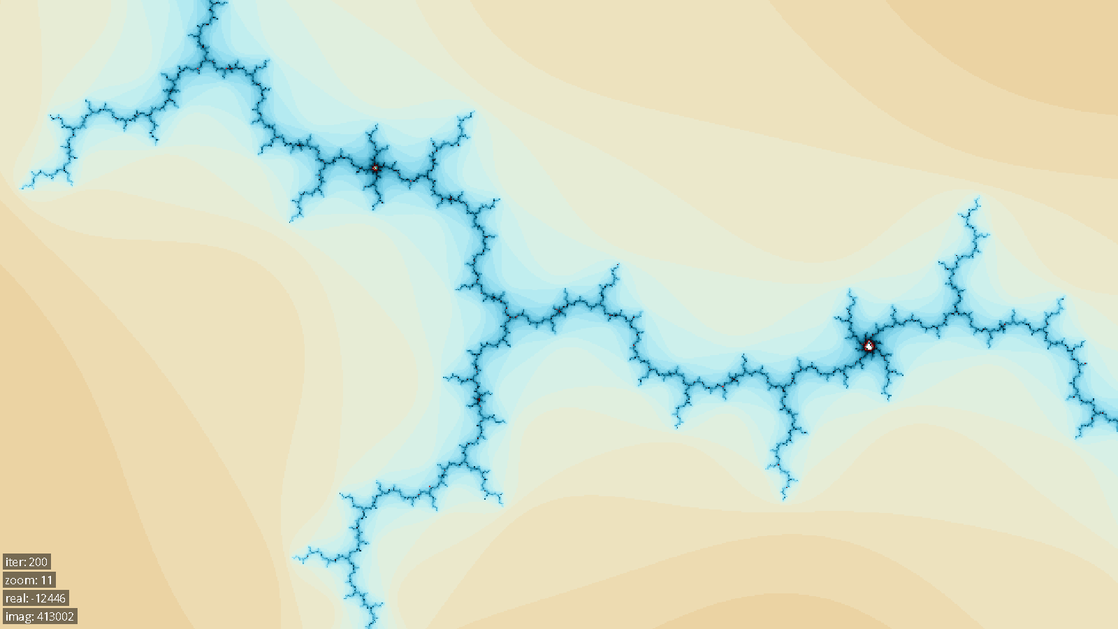
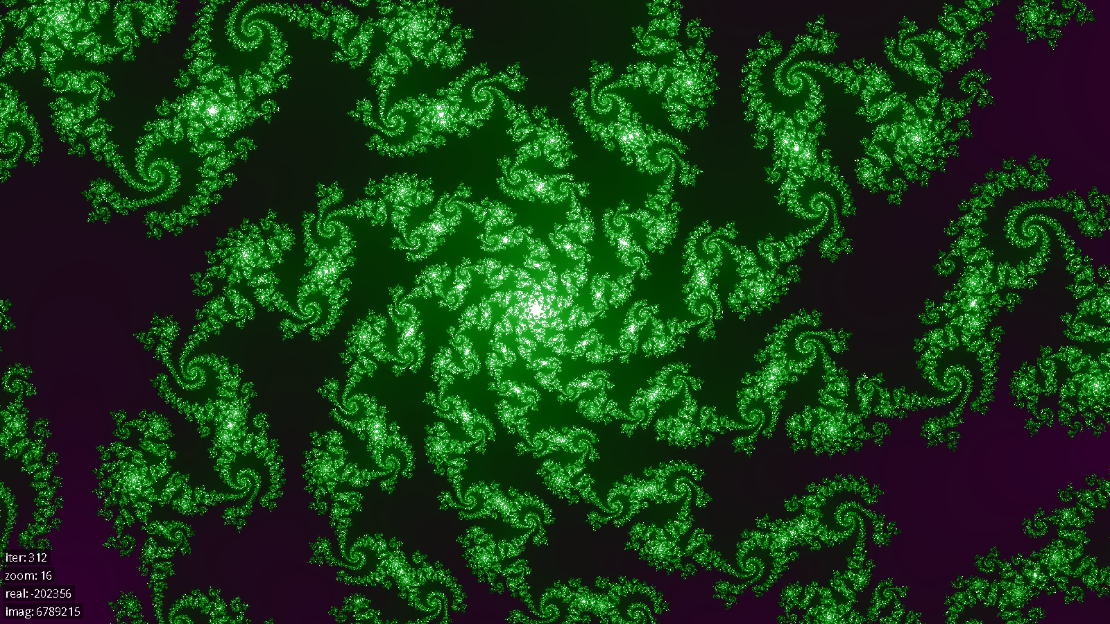
Tiles in the tile cache contain only iteration data, but do not have any color information. To generate color data, each color channel is a function of the sine of the iteration count with differing periods and phase shifts for each color. The periods were chosen to be rational numbers with a large least common multiple (LCM), so that the color cycles will not repeat until approximately LCM iterations. In addition to red, green, and blue channels, there is also a luminance channel that controls the overall color level of the pixel (0 luminance is black, 1 is white), with a shorter period than the color channels. This causes the colors to cycle through black->color->white->color repeatedly, where each color is different from the last. This resulted in a visually pleasing coloring of the set that retains detail even at extremely high iteration counts.
Before a tile is drawn to the screen, each pixel’s iteration count is mapped to an RGB value using the above color mapping, and these colored pixels are made into a renderable texture. Because this coloring is too expensive to do every frame (and also because texture creation is expensive), these colored textures are stored in a texture cache. The texture cache is much smaller than the tile data cache because color generation is much less expensive than tile generation. Generally, good performance is achieved as long as the texture cache is large enough to fit one whole viewport at a time.
Once tiles are generated and colored, the renderer draws them to the screen. If a tile is missing from the cache (i.e. hasn’t been sent back from the server yet), the renderer will try to display a lower resolution (lower z-level) tile in the same position, up to a limit of 5 z-levels below the current resolution. This results in much smoother zooming because lower resolution tiles can be rendered while the higher resolution tiles are computed.
Bus Design
The communication between the FPGA and the hard processor system happens over a memory-mapped AXI bus. Requests for tiles are placed into a FIFO on the FPGA, and solved tile data is written out into external SDRAM memory.
When the hard processor system has a request to submit, it converts the request to a format that was designed for easy decoding on the FPGA. This format, in short, consists of a series of 32-bit values, of which the upper 3 bits are used to specify the type of the current value (ie, whether it is an output address, the zoom level, or a limb of the complex number representing the tile’s upper lefthand corner), and the lower 29 bits are used to encode the value itself.
This request is then sent over the AXI bus into a FIFO located on the FPGA. A request distributor then pulls the message off of the FIFO using the avalon streaming interface, and either sends it, one word at a time, to an unoccupied tile solver or waits if they are all occupied. This design allows tile solvers to immediately receive a new request once they become free, meaning that we have high solver utilization. At the same time, the latency of a tile being solved is minimized because there is only a single queue of tiles across all solvers and distribution happens at the last possible moment. This is superior to schemes where, for example, each solver has its own queue and work distribution happens on the HPS because in such a scheme, a tile might get stuck waiting in a queue behind a particularly difficult tile while other solvers are free.
As the solvers solve pixels of the output tile, they write the results to SDRAM. We then have arbitration logic which collects results from any solvers which are ready to write. The arbitration is quite simple, and just chooses the solver with the lowest id that has a result ready.
Note that the FPGA has no special mechanism to notify the HPS that a result has been computed. The HPS determines that a tile has been completed by writing a sentinel value, -2, into the last pixel of an output tile. Since this is not a legal pixel solution value, the HPS is able to poll the value at this last pixel, and determine that once -2 has been overwritten with another value, the tile solving is complete.
Testing Methods
Each of the verilog modules in our design has at least one individual test bench which allows us to test it in simulation. This is important because the compile-test cycles can be quite long when compiling for the actual FPGA. In addition to the per-module tests, there is also a larger integration test which runs all of the components together, starting at the request distributor and ending with the write arbitrator. This test allows us to solve tiles in simulation using multiple solvers, and even outputs the results in a format that can be displayed with a special python script. This allows us to manually verify that the images of the mandelbrot set are being generated correctly.
In addition to the FPGA solver, we also developed a solver in C++ that can run on a standard desktop computer. The benefits of this were twofold: first, it allowed us to test our algorithms and verify them before implementing them in difficult-to-write verilog, and second, it allowed us to test the C++ components of our system conveniently without access to specialized hardware.
Documentation
Hardware
module solver #(
parameter LIMB_INDEX_BITS = 6,
parameter LIMB_SIZE_BITS = 27,
parameter DIVERGENCE_RADIUS = 4
) (
input clock, reset,
input wr_real_en,
input wr_imag_en,
input [LIMB_INDEX_BITS-1:0] wr_index,
input [LIMB_SIZE_BITS-1:0] real_data,
input [LIMB_SIZE_BITS-1:0] imag_data,
input wr_num_limbs_en,
input [LIMB_INDEX_BITS-1:0] num_limbs_data,
input wr_iter_lim_en,
input [15:0] iter_lim_data,
input start,
output out_ready,
output [15:0] iterations
);
The solver can compute a single pixel in the mandelbrot set. It has two ram modules to store the real and imaginary components of the pixel it is solving. You must first load in the c value you would like it to compute, then you can instruct it to begin solving by pulsing the start signal.
module tile_solver_legit #(
parameter TILE_WIDTH_BITS = 5,
parameter LIMB_INDEX_BITS = 6,
parameter LIMB_SIZE_BITS = 27,
parameter DIVERGENCE_RADIUS = 4
) (
input clock,
input reset,
input [31:0] in_data,
input in_valid,
output reg in_ready,
// Assert in_end_of_stream after the input packet has been provided.
// The next cycle must have in_valid = 0 (no data moves)
input in_end_of_stream,
output reg [31:0] out_addr,
output reg [15:0] out_data,
output reg out_valid,
input out_ready
);
A tile_solver_legit knows how to communicate with the HPS and how to use its solver to solve each pixel in the tile it’s working on.
Software
class complex {
public:
mpf_class real;
mpf_class imag;
complex(mpf_class real_, mpf_class imag_);
bool operator==(const complex& other) const;
std::vector<uint32_t> get_real_limbs(int limb_bits) const;
std::vector<uint32_t> get_imag_limbs(int limb_bits) const;
};
The complex class represents a point in the complex plain. It uses mpf_class from the GMP Multiple Precision Library to represent floating point values with arbitrary precision.
class TileHeader {
public:
mpz_class x;
mpz_class y;
int32_t z;
int16_t iter_lim;
TileHeader(mpz_class x_in, mpz_class y_in, uint32_t z_in, int16_t iter_lim)
complex getOrigin() const;
double getSize() const;
bool operator==(const TileHeader& other) const;
struct Hasher {
std::size_t operator()(const std::shared_ptr<TileHeader>& header) const;
};
struct Comparator {
bool operator()(const std::shared_ptr<TileHeader>& a,
const std::shared_ptr<TileHeader>& b) const;
};
std::vector<uint8_t> serialize();
static std::unique_ptr<TileHeader> deserialize(const std::vector<uint8_t>& data);
std::string get_str();
};
The TileHeader class contains the (x, y, z, i) data necessary to uniquely identify a tile. It uses mpz_class from the GMP Multiple Precision Library to represent integers of arbitrary size. TileHeaders are used to specify tile requests, so they must be serializable in order to passed back and forth between client and server. TileHeaders are also used as keys into the tile cache and the texture cache, so they implement a hash function and a comparator.
class Tile {
public:
Tile(std::shared_ptr<TileHeader> header);
Tile(std::shared_ptr<TileHeader> header, std::vector<uint16_t> data);
complex getOrigin() const;
double getSize() const;
bool hasData() const;
std::shared_ptr<TileHeader> getHeader() const;
std::vector<uint16_t> getData() const;
uint16_t getPoint(int x, int y) const;
void setPoint(int x, int y, uint16_t value);
};
A tile consists of a TileHeader, a vector of iteration data, and a flag that specifies whether the iteration data is valid.
class TileManager {
public:
TileManager(std::vector<std::tuple<std::string, int>> ip_addrs,
int cache_size, int request_depth = 30);
std::shared_ptr<Tile> requestTile(std::shared_ptr<TileHeader> header, int depth);
std::set<std::shared_ptr<Tile>> loadViewport(Viewport viewport);
int16_t getIterations();
void setIterations(int16_t iterations);
void clearRequests();
};
The TileManager is responsible for giving the Renderer all the tiles it needs to draw the current viewport. When the Renderer calls TileManager::loadViewport(), the TileManger builds a set of tiles that will span the viewport and then requests each of those tiles from the server. The TileManager has a TileClient for each server that it is connected to, which it uses to request and receive tiles from the server. The TileManager also manages the tile cache.
class Renderer {
public:
void setColorPhases(float r, float g, float b, float l);
void setColorPeriods(float r, float g, float b, float l);
void randomizeColors();
void scaleColors(float s);
void render(const std::set<std::shared_ptr<Tile>>& tiles,
Viewport viewport,
SDL_Renderer* sdl_renderer);
};
The Renderer takes a set of tiles, colors them, and draws them to the screen at the appropriate scale and location. Because tile coloring is expensive, the Renderer also manages a texture cache to avoid coloring the same tile multiple times.
class TileClient {
public:
TileClient(std::string ip_addr, int port);
void init();
void requestTile(std::shared_ptr<TileHeader> header);
std::unique_ptr<Tile> receiveTile();
};
The TileClient manages the state necessary for communicating with a server. The TileClient opens a socket connection with a server and can send and receive packets of serialized data. It sends tile headers when they are requested, and receives tiles when the server generates them.
class TileServer {
public:
TileServer(int port);
void init();
int awaitConnection();
void serveForever();
};
The TileServer runs on the HPS and facilitates communication with one or more TileClients. It listens for tile requests, adds them to a queue to be processed by the solver, and then sends the data back to the client.
class Solver {
public:
typedef std::unique_ptr<volatile int16_t[], std::function<void(volatile int16_t*)>> data;
virtual ~Solver() = 0;
void sumbit(std::shared_ptr<TileHeader> header);
Solver::data retrieve(std::shared_ptr<TileHeader> header);
protected:
void freeListAppend(volatile int16_t* data);
virtual void queueTile(std::shared_ptr<TileHeader> header) = 0;
};
The solver is an abstract class which forms the interface for something that can solve tiles. The two implementations we have are the CPUSolver which can be run entirely on a computer, and the FPGASolver which communicates with the FPGA, where the actual tile solving is done. Requests can be submitted to the solver and then later the tile data can be retrieved from the solver. The submit function is non blocking and simply allocates space for the solve data and then calls queueTile on its implementing class. The retrieve function is also non blocking and returns nullptr if the tile is not yet available. When the solver is instantiated, it allocates all the space it will need for all of the potential tile requests it can handle at once. In the case of the CPU solver, this is done on the heap, and in the case of the FPGA solver, this is done in SRAM. Once the tile data is no longer needed by whoever retrieved it, its destructor calls freeListAppend to put the tile solver data slot back on a freelist which the submit function can later allocate to.
Results
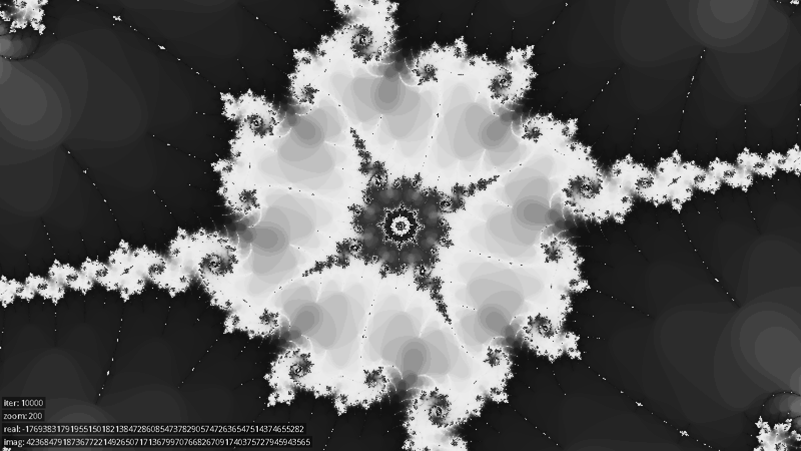
The solver we created was quite fast. As one point of comparison, it took 0.571 seconds to render the initial viewport on a single FPGA at 128 iterations, as compared to 10.14 seconds on a quad core Intel Core i7-4700HQ, which is a improvement of over 17x. Similarly, to generate the first image below from scratch, at zoom level 200 and an iteration limit of 10,000, took 858.3 seconds on the Core i7, and 27.49 seconds on a single FPGA, which is a speedup of over 31x.
We were able to fit 29 solvers on the FPGA, running at a frequency of 100 MHz. Interestingly, the bottleneck that we ran into that prevented us from instantiating more solvers was the number of logic units on the FPGA. This was contrary to our expectation, which was that the bottleneck would be the number of DSP units available. The final design used 29897 out of the 37070 available ALMs (93%). A single solver module takes ~960 ALMs, with the following breakdown:
Module | ALMs |
Tile Iteration / Bitstream decoding | 175 |
Pixel Solver | 791 |
| 77 |
| 714 |
Note that the data path is by far the most expensive piece of a solver. This is likely due to the multiple adders and multiplexers it contains.
We can theoretically zoom to a magnification level of 21700 (this is where we run out of solver memory), and have verified in practice that zooms work up until 2260. Tile solving slows down as you zoom in, so at the initial zoom levels, we can solve areas of the mandelbrot set at interactive rates, but at extremely high zoom levels, users might need to wait a few seconds before a region appears.
Below are several images generated by our system.


Conclusions
In conclusion, this lab was successful.
If we had more time to improve our design, we could have spent more time working to reduce device utilization to free up resources for more solvers. We could have also worked to increase the clock rate of the solvers. One way to accomplish both of these things would have been to move the accumulators for multiplications into the DSP units available on our FPGA. The multiplications were occurring in the DSP units, but our accumulation step happened in logic elements on the FPGA. Switching to the DSP units would both improve the propagation delays involved because the addition would be happening in dedicated hardware units while simultaneously freeing up device resources. In the end, the solver frequency was limited by the propagation delay in the accumulator as well as between the solvers and the write arbitration logic. For the latter case, we could have inserted more pipeline registers between the solvers and the write arbitrators.
We also researched ways to improve our solver algorithm. One potential way was writing an epsilon solver, which would have taken advantage of perturbation theory and series approximation to improve performance. The idea is that once the iteration series for one pixel is computed in expensive high precision arithmetic, it can be used to solve nearby pixels with much faster single-precision arithmetic. This is because, rather than computing the iteration series, you can just compute the difference (epsilon) from the high precision reference series, and this epsilon series can be computed in single-precision. According to Wikipedia and other sources, this method can provide anywhere from a 10x to 100x performance increase at high zoom levels. Unfortunately we didn’t have time to implement this optimization.
Another thing we considered was including cycle detection, where you can detect early on that if, while solving a pixel, you visit the same z value twice, the point will definitely be in the mandelbrot set. This has the potential to significantly speed up solving tiles which are largely in the set. We actually did implement this improvement, but it unfortunately used so many logic elements that we decided the tradeoff wasn’t worth it. As a result, cycle detection wasn’t included in our final product. It’s still an open problem as to whether cycle detection could be done cheaply enough to make the tradeoff worth it. Both methods of speeding up the solver would be worth evaluating in later designs.
It’s also apparent to us that we could have improved the FPGA/HPS interface in a few ways. One issue with the current write arbitration logic is that when multiple solvers are trying to write to SDRAM, the one with the lowest id wins. This can lead to issues with starvation; suppose that the 10 lowest ID solvers are solving easy tiles. In this case, at least one of them will be ready to write on every cycle and will starve the higher ID solvers from ever making progress. While we haven’t measured how often this actually occurs in practice, it would be worthwhile to research using a more intelligent scheme like round-robin for write arbitration. We could also have likely reduced latency a bit if we put in the additional work to use interrupts instead of polling or written into the HPS’ DDR3 RAM instead of the external SDRAM. Unfortunately, either of those two solutions would have required writing linux kernel drivers, which was outside of the scope of this project.
We observed that the renderer stutters and has an inconsistent framerate while transitioning to a new zoom level. This is because tile coloring is done on the same thread as rendering, and there can be a significant amount of computation needed to color a whole layer of new tiles. An improvement would be to move coloring to a background thread, which would fix the framerate issues. Another possible solution would be to optimize or hardware accelerate tile coloring, or even move coloring to the FPGA.
Another client-side improvement that we would have liked to have made was to improve the multi-server connection logic. The current implementation uses round robin request allocation, so if one server is slowly solving difficult tiles, it will limit the solve rates of all the other servers. A better solution would be to keep track of how many outstanding tile requests had been sent to each server and always send new requests to the server with the smallest queue.
Some external libraries and IP were used during the development of this project. The FIFO instantiated on the FPGA, along with the Avalon bus structure and SDRAM controller that we used, were all Altera IP. The C++ code also used the GMP library to store arbitrary precision integers, as well as SDL2 for the display and input handling.
Work Distribution
Code
Max wrote the single-pixel solvers in verilog and the corresponding arbitrary precision arithmetic. Mike wrote the modules on the FPGA that perform request distribution, request decoding, tile iteration, and write arbitration. Jon wrote the majority of the C++ code, including the HPS tile server and the display client, including coloring and rendering the tiles.
Report
Max wrote the hardware section. Jon wrote the software section. Mike wrote the bus design section, testing section, and work distribution section. The results and conclusion sections were split evenly.
Appendix A
The group approves this report for inclusion on the course website.
The group approves the video for inclusion on the course website.
Appendix B - References
Altera Avalon Bus documentation:
Altera FIFO Documentation:
http://www.altera.com/literature/hb/nios2/qts_qii55002.pdf
The GNU MP Bignum Library:
SDL2:
Appendix C - Source Code
code/hardware/request_distributor.sv
code/hardware/multi_tile_solver.sv
code/hardware/write_arbitrator.sv
code/hardware/tile_solver_legit.sv
code/hardware/solver_control.v
code/hardware/solver_datapath.v
code/software/sdl_input_controller.cpp
code/software/sdl_input_controller.h
code/software/tile_request_heap.cpp
code/software/tile_request_heap.h
code/software/tile_request_packet.h
code/software/tile_manager.cpp