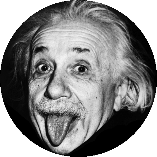
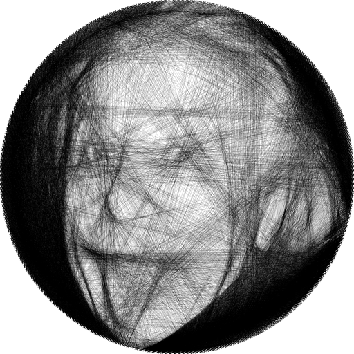
Our final project was inspired by a hardware invention posted on the fantastic Youtube channel Barton Dring, in which he built a fully automated machine to manufacture circular framed "string art" pieces from a continuous thread, that look just like the rendering shown below.
The algorithm that Barton used to derive the processed images was developed by computer graphics researchers at TU Wien (Vienna University of Technology), which is outlined in detail in this paper. In it, they formulate the problem mathematically and present their trials of different optimization methods to approach a good result, which in the end is judged subjectively by the human eye (as art should be, although they do present quantitative evaluation as well).
We will explain the algorithm in detail below, but the problem with the researchers' implementation of it in MATLAB is that it runs extraordinarily slow. Most of the inefficiency is a result of MATLAB being a script language that is compiled during execution. It took over 3 hours to generate the image of Albert Einstein above, and takes even more time for darker images that require more lines. Moreover, they have implemented matrix operations extensively to improve on the execution time from the original version, using a gigantic sparce matrix to convert from the space of edges to the space of pixels. For a 256 pin circular canvas on a 512x512 pixel image, that is a 262,144 by 130,560 matrix (assuming 4 possible edges per pin pair). This makes the code incapable of running on any computer with less than 32 GB of RAM, and even on a computer that satisfied such hardware requirements it filled 100% of the available memory.
Thus our goal was to implement specialized solvers on the FPGA, and accelerate the computation of this greedy optimization problem. Since Barton is making his hardware design open-source, this would contribute to allowing more people to build the full system without needing a high-end computer and a MATLAB license. We were successful in implementing a reduced version of the best algorithm from the paper that showed over 100x acceleration in finding the result. However, we were not able to fit the supersampling portion on the DE1-SoC's FPGA due to memory constraints. Our design is presented below as well as further steps needed to achieve an equivalent result to the MATLAB program.
As mentioned, we drew insipiration from Barton Dring's Youtube video A New Spin on String Art Machines, and based much of our algorithm development on the excellent research paper String Art: Towards Computational Fabrication of String Images by Michael Birsak, Florian Rist, Peter Wonka and Przemyslaw Musialski.
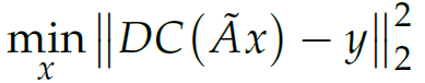
The original optimization problem is formulated in the following way by the authors of the paper: The input, y, represents all the pixels in the grascale image, each taking a decimal value in the range [0, 1] or a whole number value in [0, 255] if 8 bit depth is used. The output, x, represents a binary array for all the possible edges that can be drawn on the canvas. Note the binary assumption is important, meaning that an edge cannot be drawn twice. For simplicity we can assume that the input array is concatenated row-wise from the 2D image array. Then we assume a mapping function F that transforms from space of edges to the space of pixels, which is to say that it defines which pixels on the canvas correspond to a particular edge. Figure 3 shows this relationship well. There are two key algorithms used for discrete line drawing: Bresenham, which is binary, and Xiaolin Wu, which is weighted and anti-aliased. The optimization task can then be cast as the following:
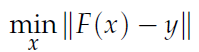
Where the norm can take on a variety of forms. The first approach that the paper experimented with is minimizing the linear least squares difference, with A being the linear mapping from edges to pixels using Xiaolin Wu algorithm:
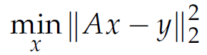
This quadratic function can be easily and efficiently solved if the number of pixels is greater than the number of unique edges. However, the result x is not constrained to the binary output that we need (can be larger than 1 or negative), so one way is to clamp the output to binary 0 or 1. A great deal of precision is lost in this step, and the image from the first approach is far from satisfactory (figure 4, c).
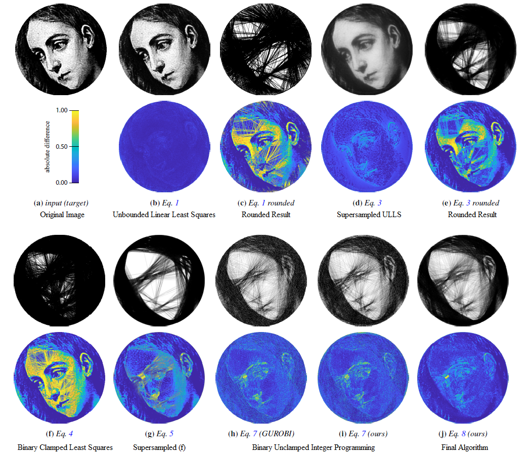
At this point the authors present two key characteristics that have a large impact on the quality of images: binary optmization and expressive range.
First, since the final image is formed by the binary process of either keeping or removing a possible edge, optimization must also adhere to it in order to retain accuracy. This means choosing binary optimization schemes instead of rounding unbounded results. Second, the image fidelity is mainly held back by the lack of expressive range of individual edges. Even if Xiaolin Wu is used instead of Bresenham for drawing edges, the pixels corresponding to a line easily accumulate values larger than 1 when intersected meaning pure black. This is problematic as the canvas will be strongly contrasted between pure white and pure black, and grayscale details of the original image get lost. It might be reasonable to think that such a problem will be solved by going to a higher dimensional space, by supersampling the original image and drawing on an equally large canvas. While it does match details much more closely, ie. figure 4 (g) vs. (f), it does not solve the fundamental problem of expressing intermediate tones.
The real solution, which the paper used on the last 3 images, is to draw lines on the supersampled canvas, then downsample to enlarge expressive range of each big pixel, and perform the difference calculation in the lower dimension space. Figure 4 (h) is their result using a downsampled unclamped integer programming scheme (meaning the pixel values are not capped at 1 when calculating difference) running on the pre-existing GUROBI optimization library. It seems like the unclamped condition was necessary to use the library, and certainly not ideal as overlapping lines can enlarge errors mathematically while in reality the maximum darkness is 1. So the algorithm will not shade dark areas as much as it needs to. Figure 4 (i) is just double-checking their GUROBI implementation, while figure 4 (j) is their custom downsampled clamped integer gramming optimization.
The clamped implementation is certainly better, as figure 4 (j) recreates dark areas with much higher fidelity. Below is the final optimization formulation, with the swiggle A being the supersampling matrix, C being the clamping operator, and D being the downsampling. The paper also talks about implementing a weighted importance map to accentuate facial features, but we can ignore that for our implementation.
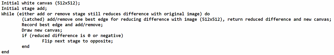
Solving this requires a custom algorithm. The authors chose to implement a greedy approach, and to ensure optimality the addition and removal of edges are interchanged when one no longer reduces the difference. A more understandable version of the pseudo-code is shown below:
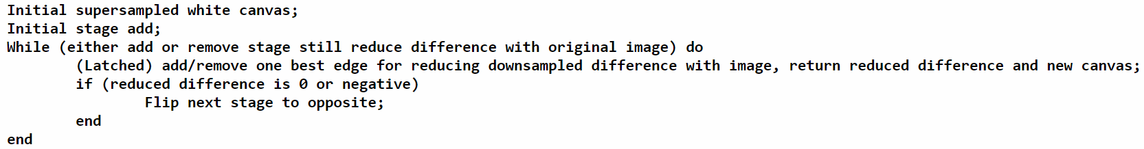
The latched add/remove state simply means that algorithm will repeat its last operation unless signaled to change when there is no longer reduction. Thus the optimization problem is complete.
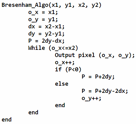
We chose to implement Bresenham's algorithm in our design, the reasons of which will be explained later. Below is a pseudo-code for the most common version. The derivations are shown here. Note that for slope greater than 1, simply exchange the x and y inputs and also exchange the x and y outputs.
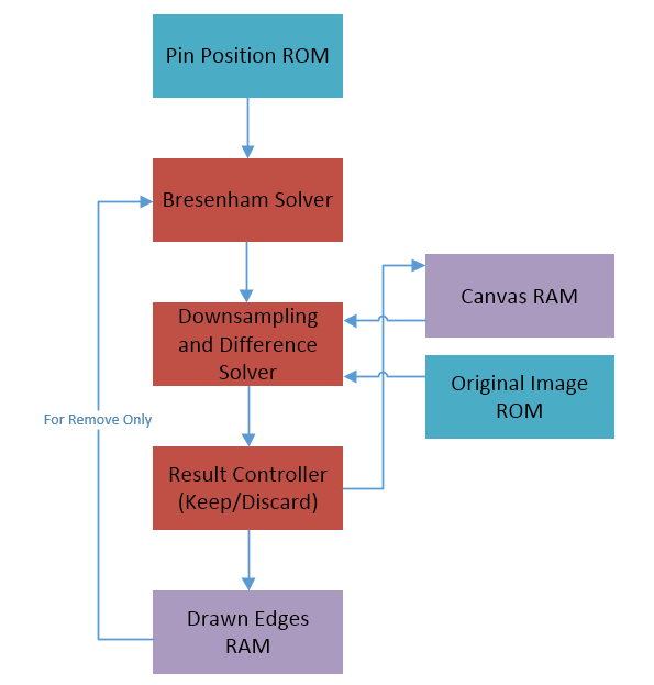
While the optmization algorithm above may not be difficult to implement in other programming languages, on the FPGA data storage and access can be rather challenging. For the process outlined by the pseudo-code above, we need a large patch of RAM to store the active canvas, which will be written to in the add/remove stage and read from when downsampling/calculating difference. The downsampling result potentially needs its own memory block, but can be buffered in registers if the difference calculation is done on the fly. The original image will also be needed but not modified, so that can be stored in a ROM patch. In addition, since verilog does not come with math libraries, the calculation of the pin pixels would have to be done with a sine/cosine lookup table if done online. That will take up storage space and repeate unnecessary calculations in each iteration, so the better option is to precompute those and also store them in a ROM block. Lastly, for manufacturability the output has to be stored as well. So the overall logical structure will be similar to the diagram below, excluding any additional processing that the HPS side could perform.
Our goal was to accelerate the solver process, so speed of execution was the first focus of the design. This means keeping as much memory as possible on the native FPGA hardware, as that allows for the lowest delay acess and highest bandwidth with the possibility of parallelism. However, since memory was never a bottleneck in previous labs, we did not realize the DE1-SoC was actually quite limited in this resource. There are only about 3900 Kbits available in M10K blocks and only about 307 Kbits available in MLAB blocks. The 1GB DDR3 external SDRAM only has 64MB available through Qsys, and the rest is managed by the HPS operating system meaning about 10 FPGA clock cycle access delays.
To put this into perspective, a 8x supersampled 512x512 image results in a 4096x4096 matrix, and assume that each pixel has 8 bits to store the canvas edge information. The canvas RAM alone represents 16MB of RAM, far more than all on chip resources combined. The original image is 512x512 with 8 bit pixel depth, so the ROM will occupy an additional 256KB. Pin position ROM is smaller with 12 bits for each coordinate (assuming 4096 pixel canvas), but two of those will be needed for simultaneous read. With the standard 256 pin frame, that is 1.5KB of ROM. Lastly, the best edge in each iteration needs to be stored as well, not just for manufacturability but also for the removal stage iteration. For easy processing and reduced storage space, we can store just the corresponding pin position pair indices (2x8 = 16 bits for 256 pins). The total size of this is rather tricky, as it really should be a dynamically managed memory that grows with the number of edges. From our simulation in MATLAB, we did not see more than 2000 edges being drawn, so 2048 appears to be an acceptable fixed memory length. This results in a 4KB block of RAM.
At this point it became obvious to us that the vanilla optimization algorithm as presented in the paper is unviable for implementation directly on our FPGA, purely due to memory constraints. The total needed memory would be 16MB + 256KB + 1.5KB + 4KB. Since we would like to have the system draw the edges in real time during the solving process, we did not want to touch the offchip SDRAM, as moving the Altera IP VGA Subsystem off the buffer could prove to be a challenge in itself. In addition, we needed simultaneous access to at least the image and canvas blocks, which would be rather complicated to convert to a serial process (and possible involve Qsys challenges) if SDRAM is used.
Thus we decided to implement a reduced version of the final optimization algorithm that can be fit in the on-chip resources. The main reduction would be to eliminate the supersampling, which also removes the need for downsampling. This makes the canvas memory significantly smaller. Also, we decided to eliminate the 4 edges per pair of pins idea, as that does not impact manufacturability, only some precision. Although the results will have similar problems as shown in some trial images of figure 4, it would show if this implementation can achieve acceleration at all. The laters steps of implementing larger storage could be done on this base algorithm, and the algorithmic improvements can then be easily made. A MATLAB version of this is linked here, and the pseudo-code is shown below.
There are no patents that we are aware of relating to this project. However, there have been previous work done on this topic in addition to the research paper that we extensively referenced. Artist Petros Vrellis has written his own algorithm for hand production of the same type of string art, even for colored versions. He has also collaborated with a father and son duo of MIT professors to create the String Art Font.
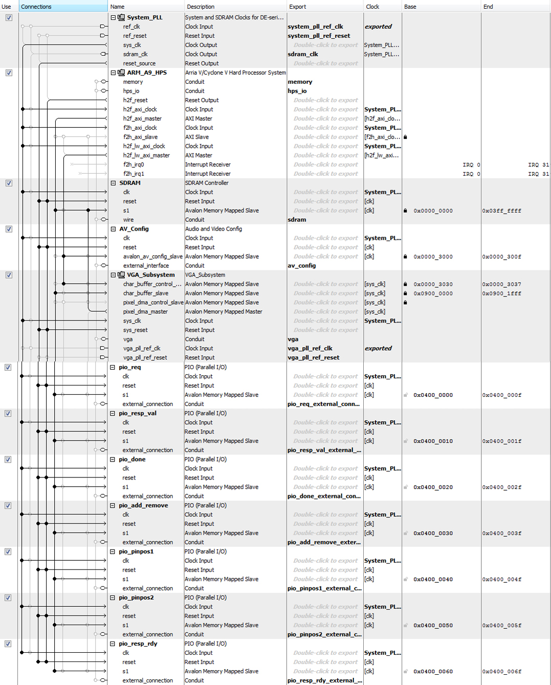
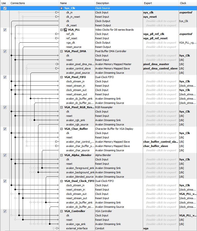
The Qsys interconnection of our design is quite simple. The bus master of HPS and output from vga DMA controller are connected to SDRAM for writing and reading the pixel value. The seven pio ports are set up for data communication between HPS and FPGA, including ready and valid signal, optimal pin pair, add or remove flag and finish signal. Following figures show the details of Qsys configuration.
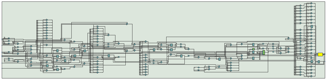
The FPGA part of our system is mainly responsible for the whole process of searching the optimal string which would be added or removed on the canvas. It can be divided into two sections, control module and computation module. The control module is responsible for adjusting the calculation mode of computation one and interacting with the HPS, while the computation module is responsible for accumulating and outputting the error reduction of each string. The detail of two modules is discussed as follows.
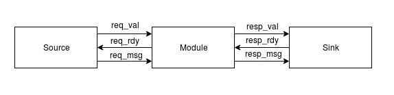
First, we want to introduce some design principles adopted in our system. Considering the mobility and robustness of the system, a well-designed and general communication interface is necessary to improve the performance and handle the problem of communication between latency-sensitive modules. Therefore, we adopted the idea of rdy/val interface, which is demonstrated in figure 9 above. It can be seen as a handshake agreement between two modules and transaction would cross the interface only if source output is valid and sink input port is ready. Even for the cross-time domain transactions like communication between HPS and FPGA, the whole system could stall waiting for the response from HPS side. Another method we used in our system is finite state machine, which could help us to divide the whole process into several steps. Therefore we could implement the system incrementally, which is easier and more efficient. In addition, the more complex the system is, the more control signals it has. However, these signals are responsible for different states. Finite state machine could help us manage and trace them better and make the system insensitive to the irrelevant control signals for certain stage.
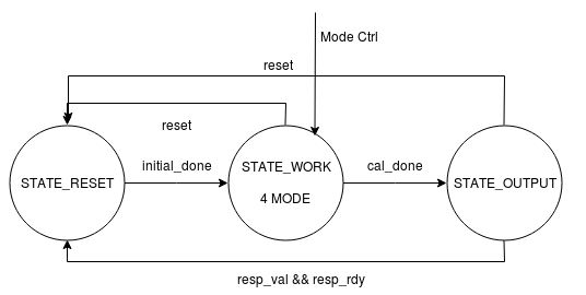
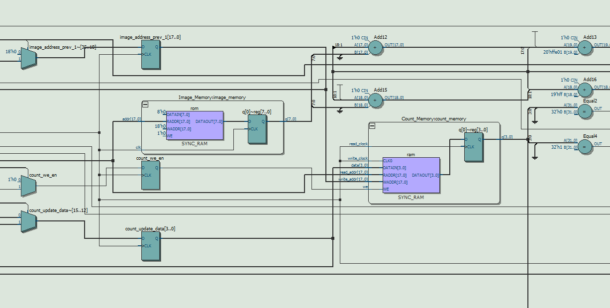
In terms of the detailed architecture of the computation module, as shown in figure 10, it contains three stages, including idle, work and output stages. In idle stage, the module will initialize the variables and waiting for the requests from control module. As soon as the request is valid, it would calculate the input arguments of bresenham algorithm in one cycle. For work stage, it has four modes to select. The module would calculate the error reduction when adding or removing a string in mode 1 and mode 3 respectively. And it would add or remove the optimal string in mode 2 and mode 4. In fact, the computation module contains two memory blocks, one ROM for reference image and one RAM for reconstructed image. Each cell in ROM stored the gray value of the corresponding pixel in the original image with 8 bits and each cell in RAM stored the count of strings covering each pixel with 4 bits. There is one thing to note that it is possible the maximum number of covering strings is out of the range of 4 bits. However, based on our MATLAB testing, the count value cannot decrease from 15 to 0 in remove stage. It is sufficient to use 4 bits to express, which is also the best we can do to fit in the DE1-SOC memory. What’s more, we need to carefully handle the latency of memory read and write, especially when updating the content of RAM block. We designed a memory address storage pipeline due to that we need to read and write back the content resulting in two cycles latency. In output stage, the module would export the results and wait for the ready signal of control module.
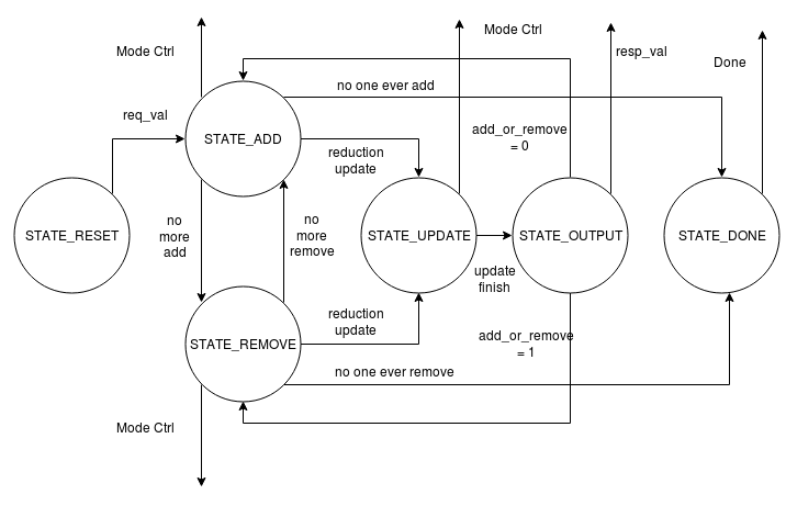
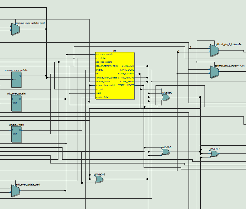
As for control module, it follows the FSM illustrated in figure 11. It is an implementation of the greedy searching algorithm to reduce the error as much as possible. As mentioned in the paper, we need to jump back and forth between adding stage and removing stage. In adding stage, the system searched for all the strings that could narrow the gap best up till now. In removing stage, the system would erased the over-evaluated strings. It also has two memory blocks, one ROM for pin position and one RAM for optimal pin pair. After reset states, in which the module would set the default value for all the signals, the module would enter add or remove states to complete the tasks described above. In this case, we should also pay attention to the latency of memory reading and computation module rdy/val interface. When the optimal pin pair indexes are obtained, the system would enter the update stage to store or remove the content in RAM block. When facing the problem of non consecutive memory after removing, we chose to set the corresponding value into 0, which was an invalid number for pin pair index. Although this method wasted some memory space, it saved the time of moving each element forward and accelerated the processing speed. Afterwards, it would wait for the response from HPS side to grab the results and draw on the screen. When it is found that no more required strings could be added or removed, the system would enter the status of completion.
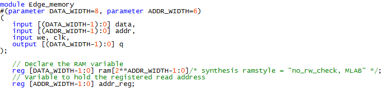
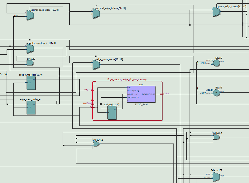
Apart from two main modules in our system, memory blocks play an important role in storing the data. There are many methods to infer memory in the design, but we directly used the template offered by Quartus software, which contains the verilog schematic for various memory behaviour. For DE1-Soc device, it offers three sources to synthesize the memory blocks, including M10K, MLAb and logic. Combining with the synthesis attribution, we can assign which source to synthesize certain module. There is one thing to mention that one memory block can only be synthesized by only one source, therefore, we need to optimize the management of resources to maximize the usage ratio of memory. In general, M10K block is preferred to store large consecutive data array with the volume of exponent of 2, while logic and MLAB are preferred to store small number of data with more flexibility. What’s more, comparing with MLAB, memory synthesized by logic is more time consuming and occupies the resources for other logic components. Considering the characteristics mentioned above, The ROM for reference image and RAM for reconstructed image are synthesized by M10K blocks, while the ROM for pixel position of pins and the RAM for added strings are synthesized by MLAB.
After obtaining the initialization file of memory from HPS side, we used the system task of $readmemh in initial block to initialize two ROMs in our design. The format is shown below. The first argument is the path of file and the second one is the memory block variable name.
$readmemh(filePath, mem)
As mentioned in high level tradeoffs, due to the sizable reduction in memory requirements when supersampling is removed, we were able to fit all 5 blocks of memory (4 different types) into hardware resources. The original image is still 512x512 with 8 bit pixel depth, and its ROM occupies 256KB. The canvas, however, is scaled down to only require 512x512 with 4 bit range, and its RAM occupies 128KB. Together with the image ROM they use up 100% of the M10K blocks (384KB). The two pin position ROM blocks and the edge RAM block are synthesized to use MLAB as mentioned above. The pin positions only require 9 bits for each coordinate now, so the total MLAB usage is around 1KB + 4KB from edge RAM block= 5KB. It is worth mentioning that we opted to use the parameterized module functionality of Verilog in constructing the different memory blocks. This way changes to the length and data width can be made easily where they are declared, and not require editing the memory file every time.
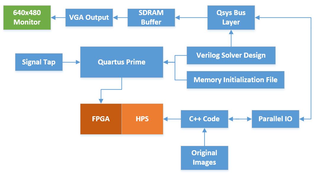
We used Video VGA 640x480 displayed from SDRAM, in 16-bit color, from the ECE 5760 University Computer Graphics page as the base of the outermost module in our design. Since we wanted to use FPGA purely for computation, this was necessary to have the HPS control realtime drawing on the monitor. We had to make some modification as shown in the Qsys design, since the original on-chip SRAM is disconnected but takes up precious memory needed by the solver. That was removed entirely, and we interfaced the rest of the system with the DE1_SoC_Computer design.
In our system, the HPS component is responsible for precomputing the reference image and pin position of pixel. What’s more, it could draw the reconstructed image on the screen in real time to demonstrate how the system works explicitly. For image processing, we turned to the library of opencv, which is easy to be installed in linux environment and offers various functions. After reading the image as gray image, we would reverse it because it is easier to calculate when reconstructing the black area. The position of pins are assumed uniformly located along the circumference. The data of image and pins’ position would be written into the file in hex format for FPGA to initialize the ROM. When FPGA is calculating, the HPS will wait for the valid data and draw the line added on the canvas. It is difficult to remove lines in real time since we cannot quickly calculate whether the pixel is covered by other strings or not. Therefore, we also had a hashset to track which one is removed. Finally, the HPS would redraw the image for performance comparison.
Since this is a rather open ended project with many algorithmic approaches, we relied on the versatility of MATLAB to experiment with ideas. We mostly used the generated images to judge if a particular approach was acceptable, and ran it with multiple images on a workstation computer (since it was very slow). Then, after writing parts of the Verilog solver, we relied on ModelSim to verify the results against the same implementation in MATLAB. Below is a snippet of the testing of the controller together with the bresenham computation module, compared against our MATLAB script output.

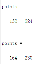
The first two lines of the ModelSim output is ready when the last line signal goes high, and represents the two pin position indices. Note that there exist a difference of 1 between both ModelSim outputs (151, 223), (163, 229) and the MATLAB results, due to the index differences of each programming language. MATLAB's indices begin at 1, hence the results are 1 larger than Verilog's which begins at 0.
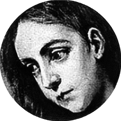
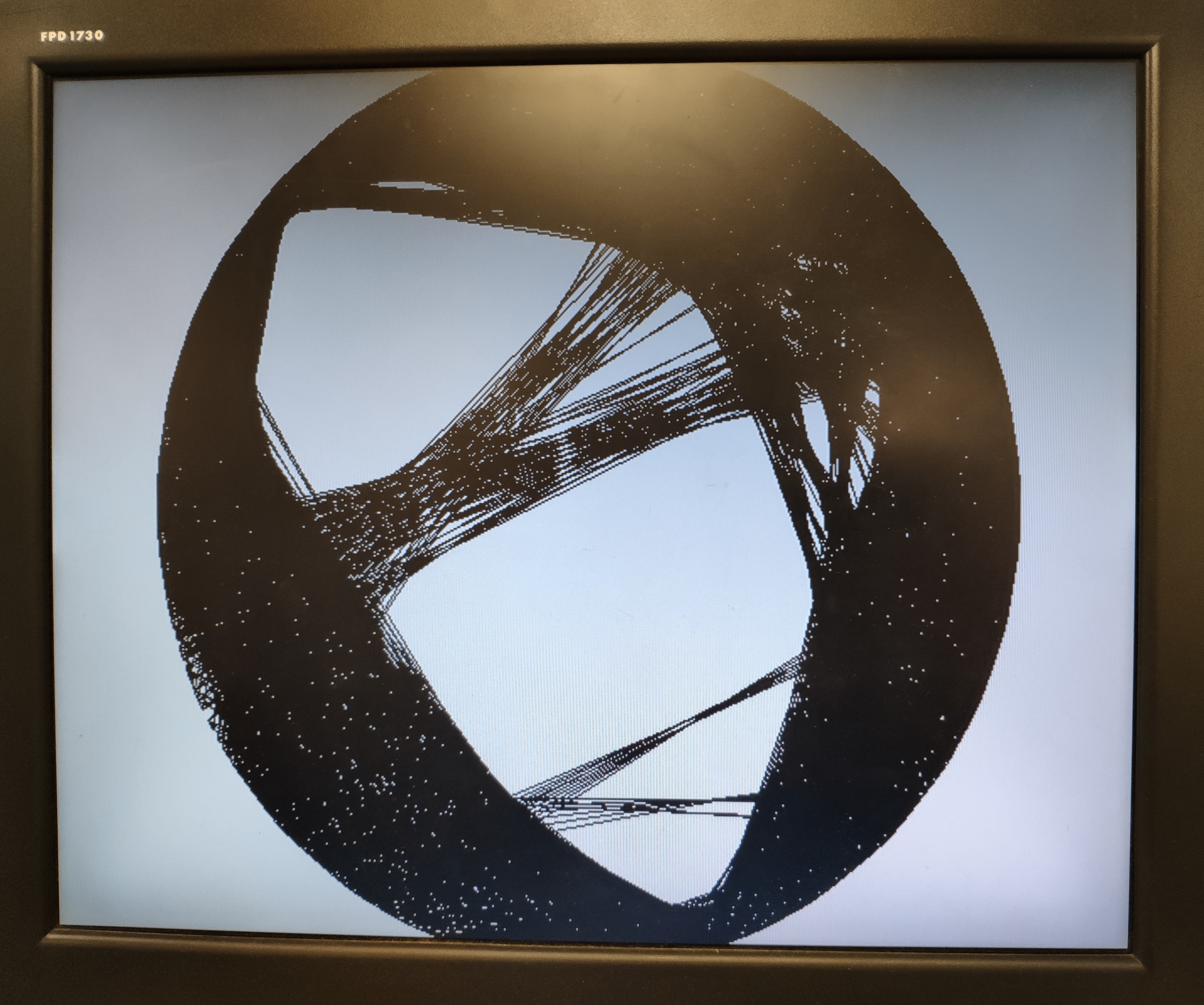
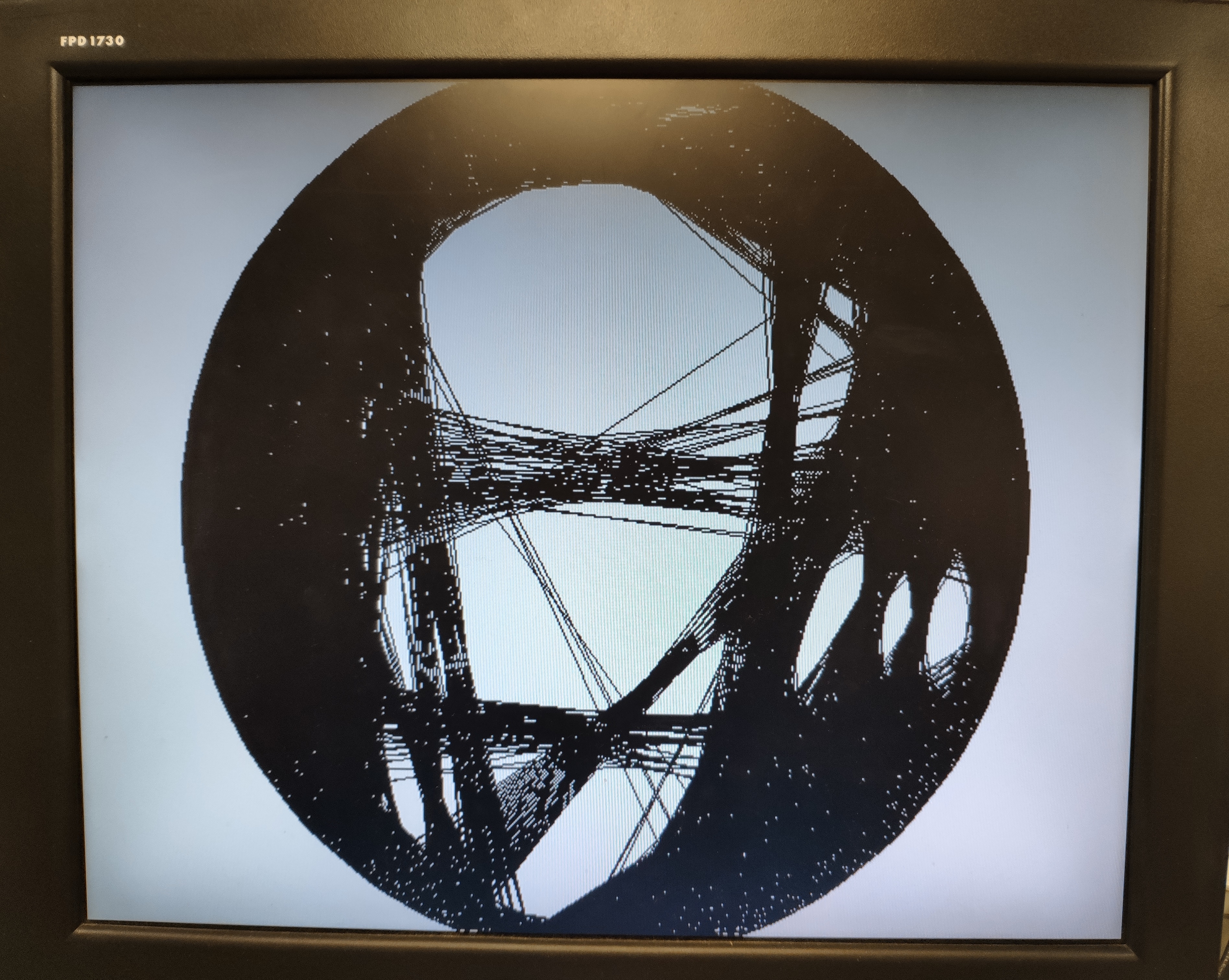

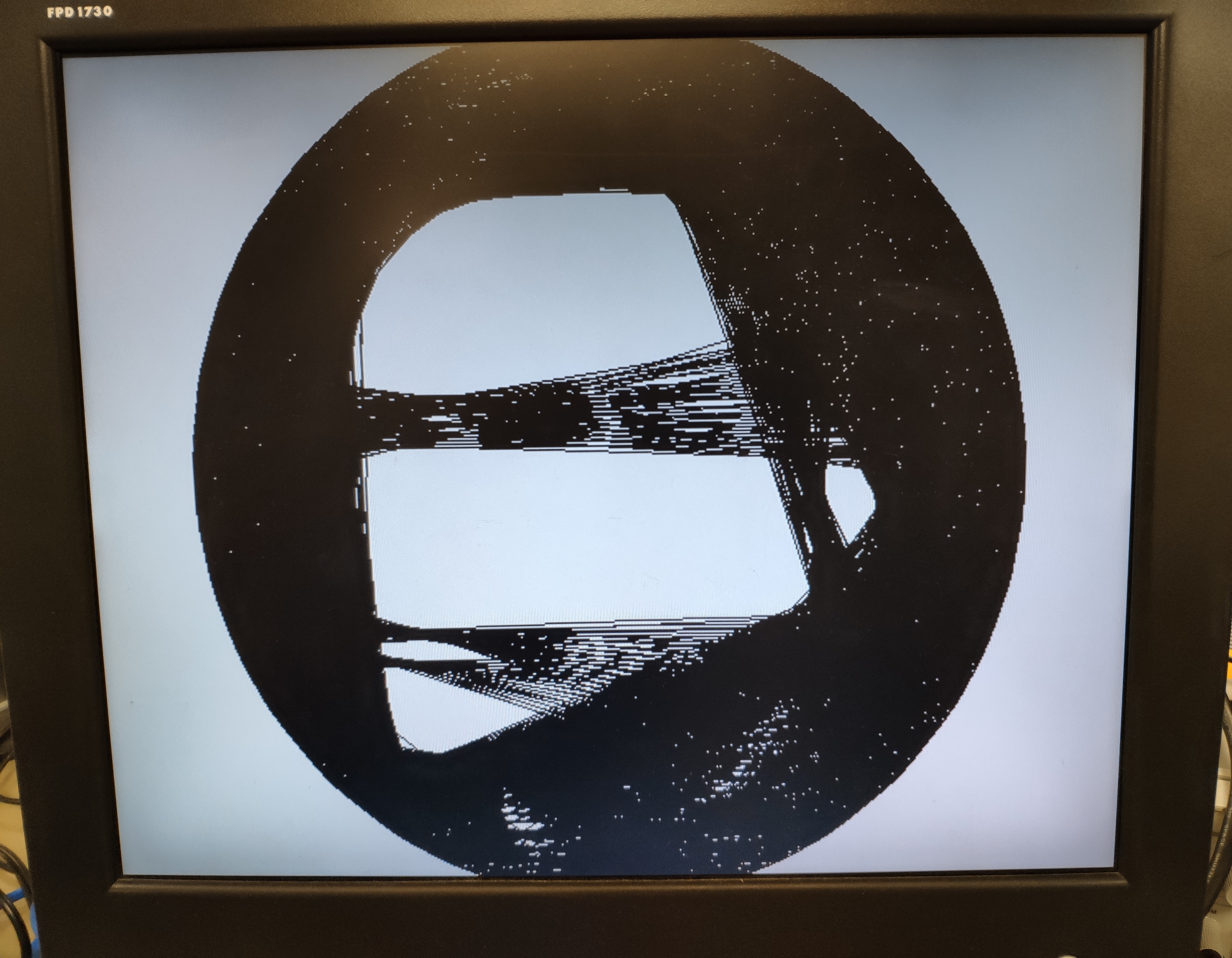

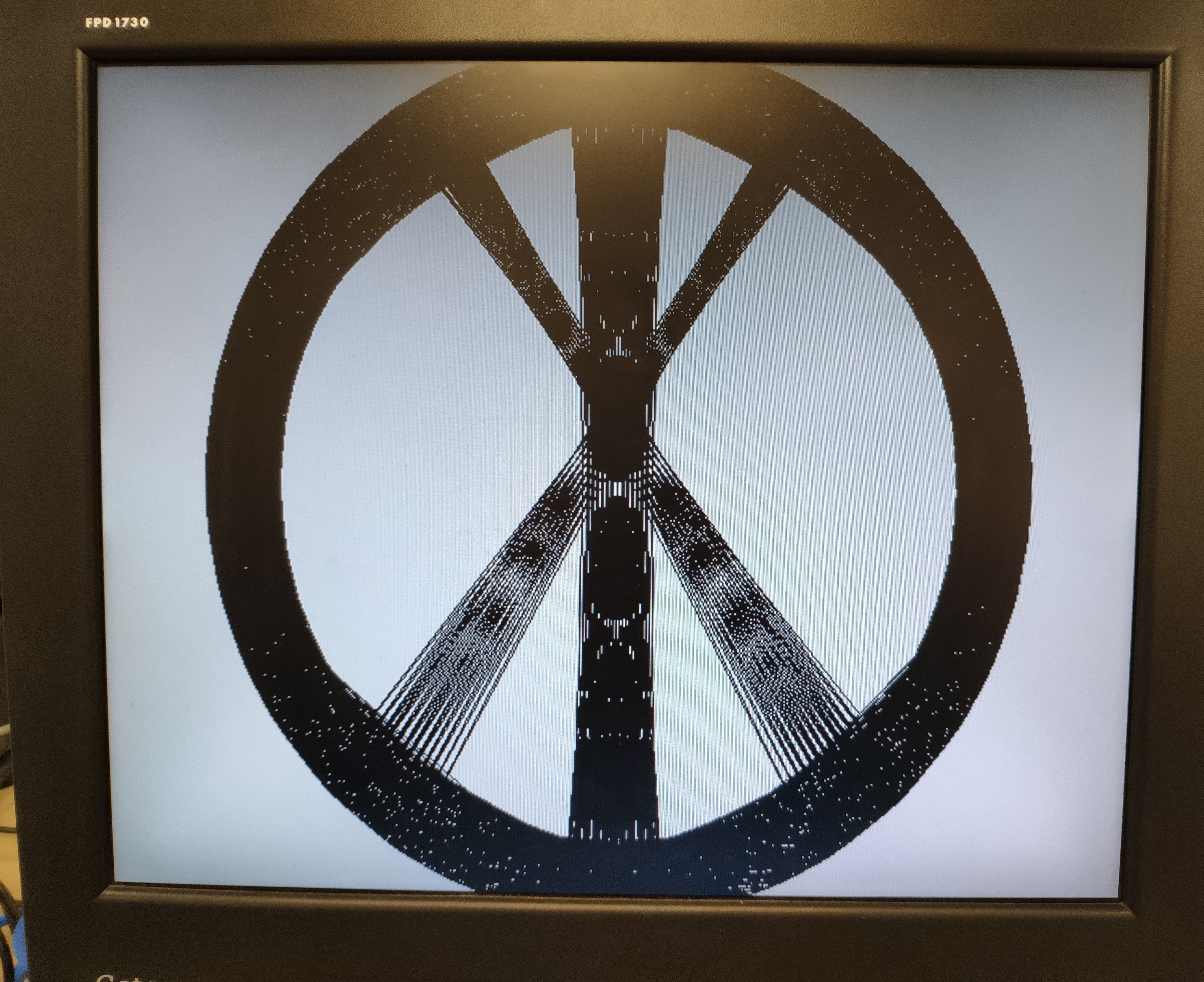
The following screenshots were obtained from running each of the above images.
We also ran some of the images above in MATLAB for comparison, with the same algorithm that we used for verification. However, not all of the MATLAB runs were completed, since they were taking upwards of 12 hours with our serial implementation (averaging 25-35 seconds per result). Since we had the MATLAB code occasionally print out running time and number of edges added, we can show the table below which compares their relative work efficiency, in edges added per second.
| Image | MATLAB Rate (Edges Per Second) | FPGA Rate (Edges Per Second) | Acceleration (FPGA/MATLAB) |
|---|---|---|---|
| Penitent Magdalene | 0.0286 | 5.144 | 179.86 |
| Einstein | 0.0416 | 5.182 | 124.57 |
| Turing | 0.0284 | 5.108 | 179.86 |
Since most of the arithmetic is not sensitive to precision, we did not observe any differences when comparing the pin position output in the console window to our MATLAB results.
There are no safety concerns with our design.
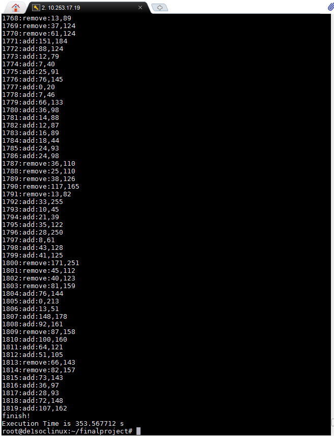
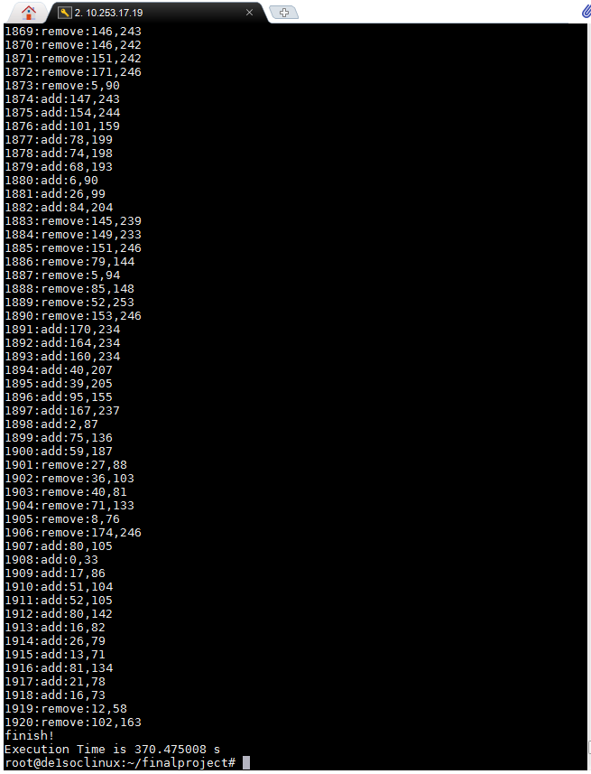
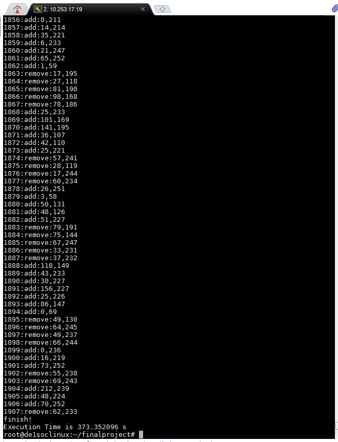
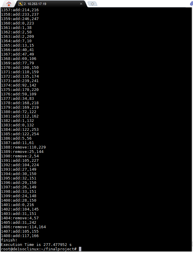
Our demonstration video shows the process of using the system, but essentially we made two different ways of ingesting a raw image. It can be done on the HPS side as explained in design, but we also wrote a simple MATLAB script that is quite efficient. Either way, it outputs a memory initialization file (with all values in hex) that needs to be put and added in the quartus project directory. The corresponding Image_memory.v readmemh needs to be changed to that new file, and the project needs to be recompiled. This is because the image ROM is written at the time of synthesis, so it is different for every new image. The process takes about 35 minutes, after which the .sof design file can be programmed on the FPGA. Then, the corresponding compiled c++ executable needs to be run in Linux on the HPS side, and immediately the system begins to draw on the VGA monitor. It outputs every edge that it deems "best" for the current iteration by printing the pin pair numbers, the number of edges added, and the current stage status (add/remove). It also indicates when the program ends by printing finish.
At the beginning we were expecting to constuct a fully equivalent system to the one demonstrated by the paper's accompanying MATLAB code. However, with some investigation we realized it was not the most realistic goal about two weeks in. Therefore, our goal became to implement this reduced system that inherited most of the techniques introduced in the paper, the scale of which was able to be fit entirely on our particular FPGA (barely). To this end, we were successful, particularly in the acceleration department. Our MATLAB code for comparison was definitely not the most efficient in terms of speed; we could have used the same matrix formulation as the paper's authors to improve on that. However, even if the best MATLAB implementation was a few times faster, the FPGA solver would still show an acceleration in the double digits. Thus, using FPGA for accelerating this particular task is proven to be valid.
The other question we have to address is the quality of image. Since this algorithm was simulated in MATLAB prior to creating the Verilog design, the drawbacks were known. When looking at our results and figure 4 (comparisons of different attempts by the paper), we would put our image quality somewhere around figure 4 (g), which is the best binary optmization result without relying on supersampling and downsampling. For grayscale images of faces in our solver, the silhouette can be clearly made out, especially if the jaw or chin lines have high enough contrast. Moreover, the eyes and mouths of the subject can be mostly made out, often carrying some details through denser intersections of lines. The areas that our implementation has particular problems with are the gray gradients in between, as well as spots of unconnected high contrast features. Due to the resolution limited by FPGA memory, our lines are exceptionally thick. This is comparable to trying to make string art with a 10 gauge wire, where the expressive range at the discernable resolution would be poor. This phenomenon is also a result of our drawing strategy. Because we are drawing the same black lines that the optimization algorithm sees, the result is equally unsatisfactory. Our C++ code also outputs a txt file with the pin position list, and using a thinner line to draw in a higher resolution space alleviated the problem slightly, in MATLAB.
Nevertheless, as the paper discusses, the solution to the central problem is still the supersampling and downsampling to calculate difference. Our current implementation proves their theory, as the lack of such a process gave way to the same issues as those earlier figures in the paper.
We came up with a few methods to implement this, although due to the extensive time needed to construct and verify the current design, we were not able to experiment with them within the 6 weeks. First, we would have to move the VGA Subsystem IP off the SDRAM to use M10K or simply go with the custom VGA that we used in lab 3, meaning that we have to use the FPGA for drawing the image exclusively. This would free up the 64MB available in the SDRAM, which would be enough as shown earlier. Second, we would have to figure out the SDRAM protocol for reading and writing data. If it is incapable of handling the amount of parallel reads/writes that our current system performs, then delay states have to be designed into our control and computation state machines, to allow for a serial process. Third, the supersampling portion is done natively by choosing a larger canvas, but the downsampling part is more complicated. Since currently we are only calculating difference along the line's pixels and nowhere else, we would like to keep that element to reduce computation. Thus, a dynamic box filter solver needs to be developed, to only recompute the downsampled pixels that the supersampled line crosses through. Then, this information needs to be passed on to the reduction calculation stage, so that it knows to only compute for those pixels and nothing else. Lastly, the display mechanism needs to be changed as well, since we would be no longer drawing a defined line but rather downsampled image pixels. The easiest way to do that is to do a clamping operation on the downsampled canvas memory, and write the results directly to the M10K block used by VGA. This way, the updated image is refreshed entirely, and matches the changed process. We could also try the Xiaolin Wu algorithm, since the downsampling requires switching to fixed point fractions anyways.
We would like to thank Professor Bruce Land for giving us ideas and the support throughout this project, and for teaching such an unique and valuable course.
We built the outer most module from ECE 5760's Video VGA 640x480 displayed from SDRAM, in 16-bit color, which uses Altera's VGA subsystem IP and SDRAM Qsys module. In addition, our instantiation of memory blocks were referenced from Altera resources. We also modified our C and C++ code from Professor Land's graphics_video_16bit.c to use the graphics primitives.
In terms of the algorithm and optimization processes, we referenced String Art: Towards Computational Fabrication of String Images extensively. We also used 2 of the paper's figures in this report's background math section, which are labeled as such. The paper's accompanying MATLAB code repository was also used to test our own algorithmic experiments, available here. A New Spin on String Art Machines is the Youtube video that originally gave us the inspiration, and we would like to give credit to Barton and his wonderful channel.
The HPS image processing code uses Eigen3 and OpenCV 3.2 libraries.
Since prior art does exist on this topic, and much of the algorithm was already developed and released into public domain, we do not see patent opportunities for this project.
During this project, we tried to maintain and follow the IEEE Code of Ethics by ensuring the safety of our project and seeking help from online resources. We credited them in text and appendix of this document.
We strove to report the results of our project in an honest and clear manner. The data we collected came directly from the computer system's timing and data channels.
The group approves this report for inclusion on the course website.
The group approves the video for inclusion on the course youtube channel.
Tasks worked on by Peng Wu: Verilog code for control module and computation module, test bench code for both modules, website design section
Tasks worked on by Kowin Shi: MATLAB Verification of the algorithm, C code for drawing lines in real time, Verilog code for computation module, website introduction and high level design sections
Tasks worked on by Zhizhong Peng: C code for image processing and pin position calculation, Verilog code for control module, website results and conclusion sections
String Art: Towards Computational Fabrication of String Images