Team Photo
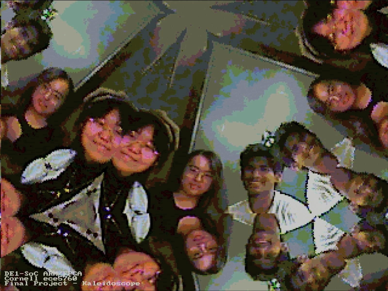
Photo of the team members taken with the real-time camera kaleidoscope
ECE 5760 Final Project: Kaleidoscope Simulator
By Devin Singh (ds2392), Kaiyuan Xu (kx74), and Wenyi Fu (wf223)
May 17, 2024
- Sound Bite: "Unveil a symphony of colors with the FPGA based Kaleidoscope Simulator, turning ordinary video into dazzling kaleidoscope art—where every glance is a burst of enchantment!"
The kaleidoscope, an optical instrument capable of producing fascinating visual patterns and transforming ordinary scenes into mesmerizing geometric art through reflections and symmetry. In the realm of digital technology, replicating such intricate and dynamic patterns in real-time poses a significant challenge, especially when aiming to deliver this experience through hardware acceleration. Our project, the FPGA-based Kaleidoscope Simulator, harnesses the power of the DE1-SoC development board to recreate the magic of a traditional kaleidoscope using live video input. This project not only captures the essence of kaleidoscopic art but also showcases the capabilities of FPGAs in handling complex, real-time image processing tasks.
Photo of the team members taken with the real-time camera kaleidoscope
A real Kaleidoscope functions using multiple mirrors facing each other, forming a series of internal reflections that reach one's eyes, and creates an illusion of repeated structures. The kaleidoscope that we have developed on the FPGA will mimic the physics of a real-life kaleidoscope, performing multiple serial internal reflections to determine what is seen by humans. These reflections will be computed using a kaleidoscope module deployed on the FPGA fabric. The deliverable of this project is a kaleidoscope generator that utilizes real-time camera data to output a kaleidoscope image onto the VGA screen using the DE1-SoC.
The fixed point notation utilized in this project was the prime determinant for the method in which we compute reflections. We utilized 12.15 notation, meaning the largest value that could be represented is 2047, and the smallest is -2047.
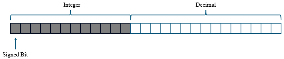
Figure 1: 12.15 fixed point representation
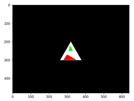
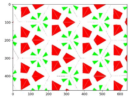
Figure 2: Python Simulation: Mirror Region (left) and Kaleidoscope after Reflection (right)
The figures above demonstrate the initial mirror region, and the expected output after kaleidoscope computations. Our kaleidoscope will be composed of three mirrors, forming a triangular region. The image that we wish to reflect will be placed within this triangular region. In the above example, the image of the red triangle and green triangle are what we expect to be reflected.
The process of determining reflections for each pixel is shown below:
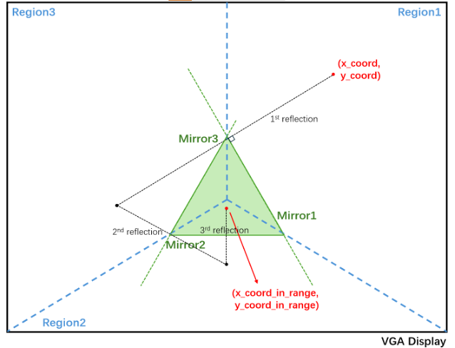
Figure 3: Kaleidoscope mathematical physics
Given a certain pixel, we first determine the region that the pixel exists in. The region that the pixel exists in corresponds to the mirror that will be used as the line of symmetry. In the example above, the coordinate given by (x_coord, y_coord) is determined to be in region 1, therefore, mirror 1 will be used as the line of symmetry.
Once the reflection is computed, we then check if the point lies within the triangle. If the point lies within the triangle, we do not reflect anymore. As can be seen in the above example, it takes multiple reflections to finally exist in the triangular region.
Once the reflected coordinate (x_coord_in_range, y_coord_in_range) is within the triangular region, it is known that the pixel data that exists at the coordinates (x_coord_in_range, y_coord_in_range) should be the same pixel data used for coordinates (x_coord, y_coord).
Once a given pixel reflection is complete, the next pixel is computed. This continues until the end of the VGA screen is met, in which case,the process begins again from the first pixel coordinate.
The reflection of a point across a line is something that is easily computed using the equation of the line, and the fact that reflections across the line are drawn perpendicular to the line of symmetry.
Our kaleidoscope region was originally defined in terms of equations of lines, in the form given below:
y = kx + b
Where k and b are the slope and y-intercept of the lines for each mirror. The lines defining mirror regions were also created using slope-intercept form as shown above. Original slope and y-intercepts for each line are provided in the table below:
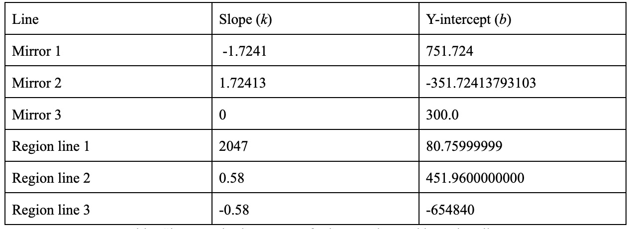
Table 1: Slopes and y-intercepts of mirror region and boundary lines
The default triangular region specified with vertices using the above slopes and y-intercepts are shown below:
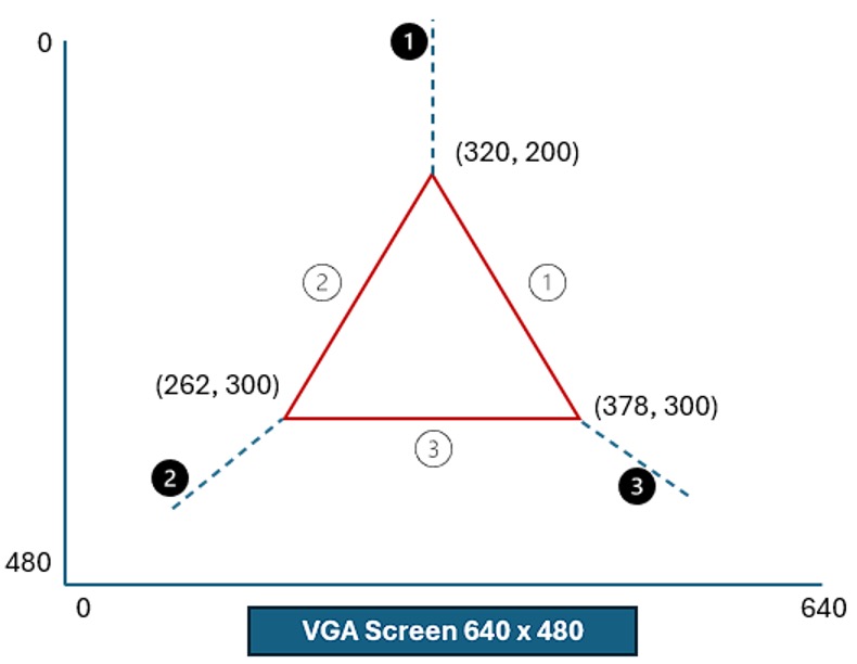
Figure 4: Coordinates and region division on VGA Screen
As noted in the fixed-point notation section above, the largest magnitude that we can represent is 2047. However, Region line 3 has a y-intercept that far surpasses this number. This fact, coupled with the fact that these numbers must also be multiplied and will continue to get larger motivated our decision to find a new method to compute mirror reflections.
The process of checking whether a point lies within the mirror boundary or not is done right before a reflection is computed.
When checking if a point exists within the triangle boundary, a vector is drawn from a triangle vertex to the point and a series of cross-products are computed between this newly drawn vector and the mirror boundaries. The signs of the cross-products determine if the point exists within the triangle boundary region.
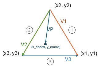
Figure 5: Vector drawn to point from vertex (x2, y2), and vectors representing mirror boundaries
Referring to the diagram above, the vector VP is drawn from vertex (x2, y2) and sample pixel coordinate (x_coord, y_coord). We then compute the cross product of vector VP and V2. If the cross-product is positive, the point is determined to not lie in the triangle. If negative, the cross product between vector VP and V1 is computed. If this product is determined to be negative, the point is determined to not lie within the triangle. If the product is positive, a new vector is drawn and the cross product between this vector and vector V3 is computed.
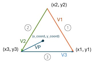
Figure 6: Vector drawn to point from vertex (x3, y3), and vectors representing mirror boundaries
If this cross-product between the newly drawn vector VP and vector V3 is positive, the point is determined to not lie within the triangle. If negative, the point is finally determined to exist within the mirror boundary region.
Representing mirror boundaries and region lines with vectors instead of in slope-intercept form allowed us to avoid the large y-intercept values that are shown above, and better manipulate our computations to prevent fixed-point overflow.
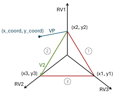
Figure 7: Vector mirror and region boundary lines with a vector drawn to a sample point to be reflected
As stated previously, given a coordinate (x_coord, y_coord), the region that the point exists in must first be determined. With vectors, this can be accomplished through cross-product calculations. Depending upon the sign of the cross product, one can determine if the point lies to the left or the right of a given vector.
When computing the region of a given coordinate, we first calculate the cross-product between region vector 1 (RV1) and the vector drawn from coordinate (x2, y2) and (x_coord, y_coord). If positive, the point lies in either region 2 or 3 (counterclockwise of vector RV1). The cross product between RV2 and VP will then be calculated, to determine if the point lies in region 2 or region 3. If the initial cross product between RV1 and VP is negative, the point lies in either region 1 or 3 (clockwise of vector RV1). The cross product between RV3 and VP will then be calculated, to determine if the point lies in region 1 or region 3.
The reflection of the point (x_coord, y_coord) across a line of symmetry is computed using vector projections. We first project the vector VP onto the mirror boundary line that the determined region corresponds with. Doing so will allow us to find the point on the mirror boundary line that can be connected to the point (x_coord, y_coord) using a new vector. This new vector is orthogonal to the mirror boundary line of symmetry. The magnitude of this vector can be doubled, making the head of the vector end the symmetrical point across the mirror boundary line.
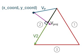
Figure 8: Vector projection onto mirror boundary line with orthogonal vector drawn between Vproj head and sample point
The vector projection calculation of VP onto V2 (Vproj) is calculated as shown below:
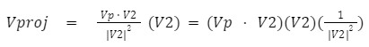
The benefit of performing the above calculation over the previous method was that the vector V2 can be scaled to whatever magnitude necessary without affecting the final calculation. This is because the dot-product in the calculation above is divided by the squared magnitude of V2 and then multiplied by V2. Notice that the reciprocal of the magnitude squared is factored outside of the other vector multiplications. This value was a constant calculated on the ARM processing system that was eventually sent to FPGA programmable logic. Unless the size of the mirror region changes, this value remains the same throughout all reflection calculations.
When performing calculations in fixed point, we scaled all mirror boundary vectors by 1/256 (such as vector V2). Doing so ensured that the dot product calculated in the equation above does not overflow our fixed point value. The effect of scaling on the above calculation is shown below:
The above formula represents how calculations were performed on the FPGA. Doing so in the above order allowed us to avoid overflowing our fixed point values.
After determining the vector Vproj, the final step is to derive the orthogonal vector and multiply it by two to obtain the reflected points coordinates.
The orthogonal vector is derived using the following equation:
The reflected coordinate is calculated using the derived orthogonal vector and the base point this vector is drawn from (x_coord, y_coord):
This reflected coordinate is then checked to be within the triangular region. If present within the triangular region, the reflected coordinate is stored into memory. If not, the calculation continues until the reflected point lies within the mirror boundaries.
For the kaleidoscope, there are two parallel processing operations in the diagram that can conduct the reflection and video input reading, which later will comprise the VGA color display. Based on the video display example from the course website, we reserve the EBAB for the video input data. Instead, the coordinates are extracted for obtaining the color information. All the modules will be fully illustrated in the following sections.
Figure 9: Kaleidoscope flow chart
As it is mentioned in the previous section, we created the reflection module with four states, RESET, TRIANGLE CHECK, REGION CHECK and REFLECTION. In the RESET state, the done signal is reset to 0 and next the state machine will go to TRIANGLE CHECK, where the coordinate will be checked whether it is inside the mirror region. If it is, the done signal will be set to high, and if not, the reflection region will be determined and later the reflection is conducted.
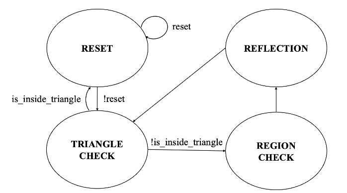
Figure 10: Kaleidoscope reflection module state machine
Since the reflection module might take several cycles to obtain the correct reflected coordinate, the M10K block is required to store all the corresponding coordinates. Hence, each x and y coordinates are concatenated together as a 20-bit parameter and stored into the M10K block. In this circumstance, the 20 x 512 size M10K is implemented, so that it will not exceed the total memory.
After obtaining the corresponding reflected coordinates, the video_in_bus_addr will be determined according to certain data read from the M10K block, and it will be used for extracting the pixel color, representing the reflection points' information.
Since the camera size is 320 x 240 and the VGA screen is 640 x 480, the kaleidoscope should be rescale to adapt the VGA display. Therefore, to display the color in the VGA, we write the adjacent four pixels with the same color by using several states in the Verilog. In addition, as it takes multiple cycles to write one camera input, the SW[9:3] should be set to a value of 15 to accommodate the VGA updating frequency.
On the FPGA, the pressing keys and the switches are applied to realize the function of resetting modules, video input and VGA screen, where KEY[0] is used to reset the whole module and SW[1] is connected to TD_RESET_N to initialize the video input signal. Moreover, SW[0] is to control the pause and resume of the video display, and SW[9:3] determines the updating frequency of the VGA screen, which makes the VGA driver catch up with the video updating when multiple pixels need to be written with the same color.
In the C program, we also created the user interface to adjust the mirror size and shape to achieve different effects. Additionally, the simulation time can be printed out in the window console and the kaleidoscope can be rotated. All the different user modes are shown in the Figure 6 with clear representations.
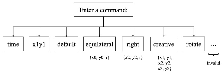
Figure 11: Kaleidoscope HPS user interface
The x1y1 command is used for testing at the beginning. The default command can initialize the mirror edge to an equilateral triangle with the height of 100 pixels in the VGA screen center. Furthermore, when switching to equilateral mode, users can define the triangle centroid coordinate and the radius between the centroid and the vertices. Next, for the right triangle shape, users can input the right vertex's coordinate and the distance to the other two vertices. Also, there is a creative mode with which the users can customize all the vertices. Finally, we have created the rotation mode, where the rotation matrix is implemented to the mirror edge, and after the calculation, the updated coordinates will be sent back into the FPGA through the PIO ports for further processing. Thus, with this command, the mirror region can be rotated 1 degree every 10,000 microseconds.
Referring to the hardware acceleration of the Mandelbrot Set Simulation, the odd and even pixels are divided to be fed into two different reflection modules and M10K blocks. Hence, we set the pixel increment of x_coord_0 and x_coord_1 both to 10'd_2 to separate the odd and even pixels along the x axis:
x_coord_0 <= (x_coord_0==10'd_318)?10'd_0:(x_coord_0 + 10'd_2) ;
x_coord_1 <= (x_coord_1==10'd_319)?10'd_1:(x_coord_1 + 10'd_2) ;
And then, the reflected coordinates is stored into the address:
M10K_write_address_0 <= (19'd_160 * y_coord_0) + (x_coord_0 >>> 1);
M10K_write_address_1 <= (19'd_160 * y_coord_1) + (x_coord_1 >>> 1);
Finally, the desired values will be extracted by the following code:
assign M10K_out_x = (video_in_x_cood[0] == 1'b1)? M10K_out_x_y_1[19:10] : M10K_out_x_y_0[19:10];
assign M10K_out_y = (video_in_x_cood[0] == 1'b1)? M10K_out_x_y_1[9:0] : M10K_out_x_y_0[9:0];
Because the reflection module consumes many DSP multipliers, only two parallel modules are implemented in this kaleidoscope simulation. With this acceleration method, the simulation time should be theoretically reduced by half.
In the experimental process, including the final demo, we used a VGA screen as the display medium, which worked pretty well; in order to record the screen display more clearly for inclusion in the report, we employed a VGA capture card. This device takes in the VGA signals and sends them to the computer via a USB port, which allows us to read the image directly in the computer camera application.
An example image is demonstrated below, and it is evident that the camera input has been flipped and replicated many times, regularly spreading across the entire screen. This kaleidoscope is designed to allow for adjustments of the shape and size of the mirror region, and even the rotation of the entire screen display, making the project more fun and engaging. However, regardless of the changes made, it still follows this pattern of repetitive and systematic arrangement to a large extent.
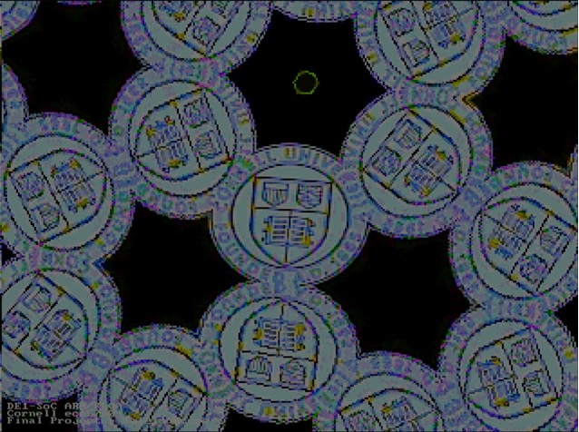
Figure 12: Cornell logo as input image for the kaleidoscope
Successful connections were established between the computer and the HPS via the command line window in MobaXterm. During the operation of the kaleidoscope, users are able to interact in real-time by entering commands through this interface.

Figure 13: Switching to the default mode
Upon entering the command "default", the mirror region is configured as an equilateral triangle centered at the coordinates (320, 240) with a radius of 67. Here, “radius” refers to the distance from the centroid of the equilateral triangle to its vertices. This setting ensures a symmetrical and precise configuration for the mirror region.
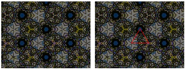
Figure 14: The original VGA display in default mode (left) and with the mirror region highlighted (right)
Figure 14 displays the general state of the display under this mode. The equilateral triangle mirror region at the center is obvious, as the image is clearly mirror-symmetric on both sides of each edge of the triangle. Compared to the expanded camera resolution, which is 640x480, the captured area is relatively small with a radius of only 67. Consequently, it is challenging to focus on a recognizable shape within this area; instead, it just displays random symmetrical patterns.

Figure 15: Switching to the equilateral triangle mode
The command for this mode is “equilateral”. Once the HPS receives the request to switch mode, it asks for the coordinates of the equilateral triangle centroid and the radius, and then waits for user input.
The mirror region set in Figure 15 remains at the center of the screen, but the difference lies in the increased radius, now expanded to 200. The corresponding result is demonstrated in figure a. With this larger triangle size, it is possible to accommodate some recognizable objects, for example, Wenyi's adorable cat Black Sugar in this sample picture Figure 16.
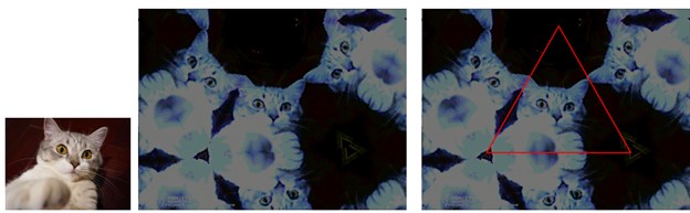
Figure 16: The original image (left), original VGA display in equilateral triangle mode (middle) and with the mirror region highlighted (right)

Figure 17: Switching to the right triangle mode
After sending command "right", inputting a coordinate (x2, y2) and a length d, the mirror region is set as an isosceles right triangle. The right-angle vertex is located at the point (x2, y2), and the lengths of the sides forming the right angle are both d, as illustrated in Figure 18 where the area is marked in red.
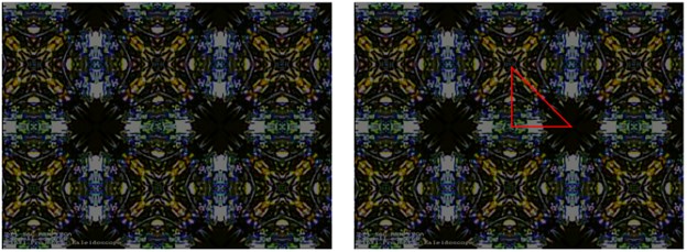
Figure 18: The original VGA display in right triangle mode (left) and with the mirror region highlighted (right)
Now that the mirror region is no longer an equilateral triangle, it requires adjustments in how the screen is divided to determine which mirror to reflect off. Recall that for the equilateral triangle mirror region, the plane is divided into three areas by rays extending from the center point to the three vertices (as shown in Figure 3). This method works well because of the unique properties of the equilateral triangle, where the centroid and the orthocenter coincide, and the symmetry is perfect. For a right triangle, placing the intersection point at the midpoint of the hypotenuse yields better results. In Figure 18, patterns exhibit square symmetry, which makes sense because two of the mirrors used for reflection are perpendicular.

Figure 19: Switching to the right triangle mode
The command for this mode is called "creative," and it requires the input of coordinates for three points. As long as these coordinates fall within the 640x480 screen range, the mirror region will be set as a triangle with these three points as vertices, allowing for triangles of any shape. The coordinates for the point that serves as the intersection of the plane regions are determined by taking the average of the vertex coordinates. The configuration entered in Figure 19 results in the mirror region being an obtuse triangle, as shown in Figure 20.
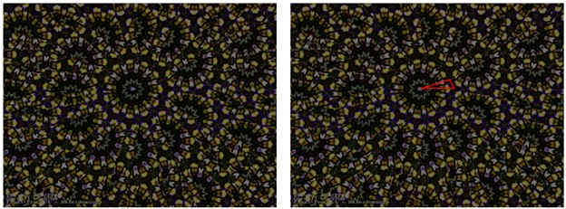
Figure 20: The original VGA display in creative mode (left) and with the mirror region highlighted (right)
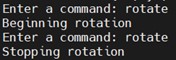
Figure 21: Toggling on and off the rotate effect
A rotational visual effect can be toggled on or off using the command "rotate". In this mode, the mirror region will begin to rotate around the point where the plane regions intersect, at a speed of 1 degree per 0.01 second. Below is a brief video that includes a demonstration of this rotating effect.
This rotational effect can be applied to any shape of mirror region, as long as the mirror region remains within the screen boundaries during the rotation. When the mirror region is relatively large, a noticeably static area can be observed on the screen. This occurs because the rotation affects the mirror region and not the camera; therefore, the area near the center of the triangle consistently displays the same image, while the coordinates outside the mirror region continuously change due to the shifting positions of the axes of symmetry, creating this beautiful dynamic effect.
Additionally, since the system utilizes real-time input from the camera, not only static images but also animations can be displayed clearly and smoothly. Please find some engaging demo videos below with dynamic visual effects from cat memes. 🐈
Recall that since the camera input size is 320x240, the reflection calculations are also based on this dimension. From the Python implementation, we get the number of reflection calculations needed for the entire 320x240 area under the default mirror region mode. This number is 315,387.
Our implementation of the reflection module requires 2 basic clock cycles + 3 cycles per reflection for each pixel. This means, for example, if a coordinate requires 5 reflections to converge within the mirror region, then processing this pixel would take 2 + 3*5 = 17 clock cycles.
Therefore, when only one reflection module is available, the time required to get the reflection result for the entire region should be approximately ((2*320*240 + 3*315387)/50000000)*1000 = 21.995 ms, 50,000,000 being the hardware clock frequency.
Originally, we used a method similar to the one employed in the Mandelbrot Set lab to measure time in Verilog. This involves setting up a counter that accumulates each clock cycle, stopping the accumulation when the calculation is complete, and then sending this counter value to the ARM processor. By dividing this counter value by the clock frequency, the elapsed time can be determined. However, this approach somehow did not work, so we tried another method.
In the alternative approach, we set a Parallel I/O (PIO) port to high at the start of the computation and to low at the end. The duration is measured directly using an oscilloscope. The results, as shown in figure 22, indicate that a single reflection module took 21.6 ms to complete the calculations, which closely aligns with our theoretical expectations.
After hardware acceleration, which involved using two reflection modules working in parallel, the time was reduced to 11.6 ms, nearly halving the original duration. The reason it did not exactly halve is due to the difficulty in achieving perfectly even workload distribution between the two modules. Nevertheless, this represents a significant improvement.
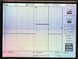
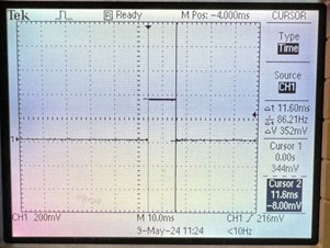
Figure 22: Calculation Time before (left figure) and after (right figure) the hardware acceleration
Regarding intellectual property, it should be noted that the physical principles of the reflection calculation method were inspired by 影叶's shader kaleidoscope project, the link to which is included in the references section.
For this project, the kaleidoscope results fully align with our expectations. It takes real-time camera input, performs reflection calculations, and then displays the final visual effect on the VGA screen. In this regard, the displayed effect is similar to that of a physical kaleidoscope. Additionally, the mirror region can be transformed into a triangle of any shape and size through a user-friendly command-line interface, resulting in a more diverse range of visual effects that a physical kaleidoscope cannot achieve. We also added a rotating effect to increase the fun and interactive aspect. Since this is a course about FPGA, we also made efforts to optimize the hardware-based solutions to enhance the performance of the kaleidoscope. After completing the basic functionalities, we implemented hardware acceleration, using two parallel computing modules to reduce the computation time from 21.6ms to 11.6ms.
We spent a considerable amount of time, nearly two weeks, to ensure the feasibility and compatibility of our algorithm. Initially we implemented the reflection calculation module in Python, then simulated the kaleidoscope effect over a 640*480 region. After verifying the feasibility of the algorithm, we transferred it to Verilog. During this process, we discovered that the original oblique truncation approach would cause overflow in Verilog's fixed-point calculations. To resolve this, we switched to a new vector-based approach and rewrote the entire reflection calculation.
Furthermore, to manage the limitations posed by memory capacity, we performed calculations at a reduced resolution of 320x240, and then rescaled and filled a 640x480 VGA screen. This strategy not only presented an interesting design challenge but also optimized the use of available resources.
After overcoming these challenges, the project proceeded quite smoothly. We learned valuable lessons about the importance of conducting thorough preliminary testing and making necessary adaptations when dealing with hardware-specific programming and design constraints in FPGA development. Overall, this was an engaging project to plan, execute, and play with.
The group approves this report for inclusion on the course website.
The group approves the video for inclusion on the course youtube channel.
Wenyi, Devin and Kaiyuan all participated in and contributed evenly to every section of this project.
import numpy as np
            import matplotlib.pyplot as plt

            # RGB values of colors
            white = [255, 255, 255]
            black = [0, 0, 0]
            red = [255, 0, 0]
            green = [0, 255, 0]
            blue = [0, 0, 255]


            # Check if the given point (x,y) is inside the triangle decided by (x1,y1), (x2,y2) and (x3,y3)
            def is_inside_triangle(x, y, x1, y1, x2, y2, x3, y3):

                # Helper function to calculate the sign of the determinant of a matrix formed by three points
                def sign(px, py, qx, qy, rx, ry):
                    return (px - rx) * (qy - ry) - (qx - rx) * (py - ry)

                d1 = sign(x, y, x1, y1, x2, y2)
                d2 = sign(x, y, x2, y2, x3, y3)
                d3 = sign(x, y, x3, y3, x1, y1)

                # Check the sign of determinants for the point with each edge
                has_neg = (d1 < 0) or (d2 < 0) or (d3 < 0)  # Any determinant negative
                has_pos = (d1 > 0) or (d2 > 0) or (d3 > 0)  # Any determinant positive

                # Point is inside the triangle when it has consistent orientation with respect to all three edges
                # Otherwise, outside
                return not (has_neg and has_pos)


            # Vector projection calculation
            # - Given vectors u and v, output vector p, which is the projection of u on v
            def vector_projection(u_x, u_y, v_x, v_y):
                p_x = ((u_x*v_x + u_y*v_y)/(v_x*v_x + v_y*v_y))*v_x
                p_y = ((u_x*v_x + u_y*v_y)/(v_x*v_x + v_y*v_y))*v_y

                return p_x, p_y


            # Scanline filling algorithm
            # - Given the coordinates of three vertices of a triangle in a region,
            # - fill the triangle with specified color
            def scanline_fill_triangle(fill_region, x1, y1, x2, y2, x3, y3, fill_color):

                # Sort vertices of the triangle from top to bottom
                vertices = sorted([(x1, y1), (x2, y2), (x3, y3)], key=lambda vertex: vertex[1])
                (x1, y1), (x2, y2), (x3, y3) = vertices

                # Compute slopes of the edges
                inv_slope_1 = (x2 - x1) / (y2 - y1) if y2 - y1 != 0 else 0
                inv_slope_2 = (x3 - x1) / (y3 - y1) if y3 - y1 != 0 else 0

                # Initialize the x coordinates of the edges
                edge_1_x = edge_2_x = x1

                # Start from top to bottom filling each scanline
                for y in range(y1, y3 + 1):
                    for x in range(int(edge_1_x), int(edge_2_x) + 1):
                        fill_region[y, x] = fill_color
                    edge_1_x += inv_slope_1
                    edge_2_x += inv_slope_2


            # Reflection module
            # - x/y0: triangle centroid
            # - x/y1-3: triangle vertices
            # - v1-3: mirror edge vectors
            # - v4-6: region edge vectors
            # Given the initial pixel coordinate, output the reflection result coordinate in the mirror region
            def reflection_compute(x, y, x0, y0, x1, y1, x2, y2, x3, y3, v1_x, v1_y, v2_x, v2_y, v3_x, v3_y, v4_x, v4_y, v5_x, v5_y, v6_x, v6_y):
                counter = 0

                # Keep iterating the reflection until the coordinate is inside the mirror region
                while not(is_inside_triangle(x, y, x1, y1, x2, y2, x3, y3)):

                    # Draw vectors from proposed point to centroid
                    vp_x = x - x0
                    vp_y = y - y0
                    counter += 1

                    # Calculate which region the current coordinate is in
                    if ((v5_x*vp_y-vp_x*v5_y)<0): # positive means on left side of V5, check V6
                        if ((v6_x*vp_y-vp_x*v6_y)>0):
                            region = 1
                        else:
                            region = 2
                    else:
                        if ((v4_x*vp_y-vp_x*v4_y)<0):
                            region = 3
                        else:
                            region = 2

                    # Calculate the reflection according to the region the point is in
                    if (region==1):
                        u_x = x-x1
                        u_y = y-y1
                        v_x = v1_x
                        v_y = v1_y
                    elif (region==2):
                        u_x = x-x2
                        u_y = y-y2
                        v_x = v2_x
                        v_y = v2_y
                    elif (region==3):
                        u_x = x-x3
                        u_y = y-y3
                        v_x = v3_x
                        v_y = v3_y

                    # Projection of the vertex-point vector on the mirror edge vector
                    p_x, p_y = vector_projection(u_x, u_y, v_x, v_y)

                    # Vector from the proposed point to mirror perpendicular
                    v_ortho_x = p_x - u_x
                    v_ortho_y = p_y - u_y

                    # Avoid stucking on the mirror edge
                    if (v_ortho_x == 0 and v_ortho_y == 0):
                        v_ortho_y = 1

                    # Get the symmetrical point of the proposed point with respect to the mirror
                    x = 2*v_ortho_x + x
                    y = 2*v_ortho_y + y

                return round(x), round(y), counter


            #################################################################
            ##################### Main Function #############################
            #################################################################

            # VGA display in the size of camera input
            width = 320
            height = 240
            screen_colors = np.zeros((height, width, 3), dtype=np.uint8)

            # Define the vertices of the equilateral triangle (mirrors)
            x1, y1 = 160, 100
            x2, y2 = 131, 150
            x3, y3 = 189, 150
            x0, y0 = 160, int(267/2)

            # Mirror edge vectors (counter-clockwise)
            v1_x = (x2 - x1)/256   # Shifted for smaller values to prevent overflow in Verilog
            v1_y = (y2 - y1)/256
            v2_x = (x3 - x2)/256
            v2_y = (y3 - y2)/256
            v3_x = (x1 - x3)/256
            v3_y = (y1 - y3)/256

            # Region edge vectors
            v4_x = (x3 - x0)/256
            v4_y = (y3 - y0)/256
            v5_x = (x1 - x0)/256
            v5_y = (y1 - y0)/256
            v6_x = (x2 - x0)/256
            v6_y = (y2 - y0)/256

            # Define some shapes in the mirror region and fill them with the specified color
            tri1_x1, tri1_y1, tri1_x2, tri1_y2, tri1_x3, tri1_y3 = 140, int(299/2), 150, 135, 175, int(299/2)
            tri2_x1, tri2_y1, tri2_x2, tri2_y2, tri2_x3, tri2_y3 = 155, 125, int(315/2), 110, 165, 125
            scanline_fill_triangle(screen_colors, x1, y1, x2, y2, x3, y3, white)
            scanline_fill_triangle(screen_colors, tri1_x1, tri1_y1, tri1_x2, tri1_y2, tri1_x3, tri1_y3, red)
            scanline_fill_triangle(screen_colors, tri2_x1, tri2_y1, tri2_x2, tri2_y2, tri2_x3, tri2_y3, green)

            # Step through the whole screen (camera input size) and calculate the reflection
            counter_max = 0     # Record the maximum reflection iteration number needed for all pixels
            counter_total = 0   # Record the total reflection iteration numbers
            for x_in in range(0, width):
                for y_in in range(0, height):
                    print("x_in:", x_in, "y_in:", y_in)
                    x_out, y_out, counter = reflection_compute(x_in, y_in, x0, y0, x1, y1, x2, y2, x3, y3, v1_x, v1_y, v2_x, v2_y, v3_x, v3_y, v4_x, v4_y, v5_x, v5_y, v6_x, v6_y)
                    print("x_out:", x_out, "y_out:", y_out, "reflection iteration time:", counter)
                    counter_max = max(counter, counter_max)
                    counter_total = counter_total + counter
                    screen_colors[y_in][x_in] = screen_colors[y_out][x_out]

            print("Max reflection iteration number:", counter_max)
            print("Total interation number:", counter_total)

            # Display the result
            plt.imshow(screen_colors)
            plt.show()
module DE1_SoC_Computer (
	////////////////////////////////////
	// FPGA Pins
	////////////////////////////////////

	// Clock pins
	CLOCK_50,
	CLOCK2_50,
	CLOCK3_50,
	CLOCK4_50,

	// ADC
	ADC_CS_N,
	ADC_DIN,
	ADC_DOUT,
	ADC_SCLK,

	// Audio
	AUD_ADCDAT,
	AUD_ADCLRCK,
	AUD_BCLK,
	AUD_DACDAT,
	AUD_DACLRCK,
	AUD_XCK,

	// SDRAM
	DRAM_ADDR,
	DRAM_BA,
	DRAM_CAS_N,
	DRAM_CKE,
	DRAM_CLK,
	DRAM_CS_N,
	DRAM_DQ,
	DRAM_LDQM,
	DRAM_RAS_N,
	DRAM_UDQM,
	DRAM_WE_N,

	// I2C Bus for Configuration of the Audio and Video-In Chips
	FPGA_I2C_SCLK,
	FPGA_I2C_SDAT,

	// 40-Pin Headers
	GPIO_0,
	GPIO_1,

	// Seven Segment Displays
	HEX0,
	HEX1,
	HEX2,
	HEX3,
	HEX4,
	HEX5,

	// IR
	IRDA_RXD,
	IRDA_TXD,

	// Pushbuttons
	KEY,

	// LEDs
	LEDR,

	// PS2 Ports
	PS2_CLK,
	PS2_DAT,

	PS2_CLK2,
	PS2_DAT2,

	// Slider Switches
	SW,

	// Video-In
	TD_CLK27,
	TD_DATA,
	TD_HS,
	TD_RESET_N,
	TD_VS,

	// VGA
	VGA_B,
	VGA_BLANK_N,
	VGA_CLK,
	VGA_G,
	VGA_HS,
	VGA_R,
	VGA_SYNC_N,
	VGA_VS,

	////////////////////////////////////
	// HPS Pins
	////////////////////////////////////

	// DDR3 SDRAM
	HPS_DDR3_ADDR,
	HPS_DDR3_BA,
	HPS_DDR3_CAS_N,
	HPS_DDR3_CKE,
	HPS_DDR3_CK_N,
	HPS_DDR3_CK_P,
	HPS_DDR3_CS_N,
	HPS_DDR3_DM,
	HPS_DDR3_DQ,
	HPS_DDR3_DQS_N,
	HPS_DDR3_DQS_P,
	HPS_DDR3_ODT,
	HPS_DDR3_RAS_N,
	HPS_DDR3_RESET_N,
	HPS_DDR3_RZQ,
	HPS_DDR3_WE_N,

	// Ethernet
	HPS_ENET_GTX_CLK,
	HPS_ENET_INT_N,
	HPS_ENET_MDC,
	HPS_ENET_MDIO,
	HPS_ENET_RX_CLK,
	HPS_ENET_RX_DATA,
	HPS_ENET_RX_DV,
	HPS_ENET_TX_DATA,
	HPS_ENET_TX_EN,

	// Flash
	HPS_FLASH_DATA,
	HPS_FLASH_DCLK,
	HPS_FLASH_NCSO,

	// Accelerometer
	HPS_GSENSOR_INT,

	// General Purpose I/O
	HPS_GPIO,

	// I2C
	HPS_I2C_CONTROL,
	HPS_I2C1_SCLK,
	HPS_I2C1_SDAT,
	HPS_I2C2_SCLK,
	HPS_I2C2_SDAT,

	// Pushbutton
	HPS_KEY,

	// LED
	HPS_LED,

	// SD Card
	HPS_SD_CLK,
	HPS_SD_CMD,
	HPS_SD_DATA,

	// SPI
	HPS_SPIM_CLK,
	HPS_SPIM_MISO,
	HPS_SPIM_MOSI,
	HPS_SPIM_SS,

	// UART
	HPS_UART_RX,
	HPS_UART_TX,

	// USB
	HPS_CONV_USB_N,
	HPS_USB_CLKOUT,
	HPS_USB_DATA,
	HPS_USB_DIR,
	HPS_USB_NXT,
	HPS_USB_STP
);

//=======================================================
//  PARAMETER declarations
//=======================================================


//=======================================================
//  PORT declarations
//=======================================================

////////////////////////////////////
// FPGA Pins
////////////////////////////////////

// Clock pins
input						CLOCK_50;
input						CLOCK2_50;
input						CLOCK3_50;
input						CLOCK4_50;

// ADC
inout						ADC_CS_N;
output					ADC_DIN;
input						ADC_DOUT;
output					ADC_SCLK;

// Audio
input						AUD_ADCDAT;
inout						AUD_ADCLRCK;
inout						AUD_BCLK;
output					AUD_DACDAT;
inout						AUD_DACLRCK;
output					AUD_XCK;

// SDRAM
output 		[12: 0]	DRAM_ADDR;
output		[ 1: 0]	DRAM_BA;
output					DRAM_CAS_N;
output					DRAM_CKE;
output					DRAM_CLK;
output					DRAM_CS_N;
inout			[15: 0]	DRAM_DQ;
output					DRAM_LDQM;
output					DRAM_RAS_N;
output					DRAM_UDQM;
output					DRAM_WE_N;

// I2C Bus for Configuration of the Audio and Video-In Chips
output					FPGA_I2C_SCLK;
inout						FPGA_I2C_SDAT;

// 40-pin headers
inout			[35: 0]	GPIO_0;
inout			[35: 0]	GPIO_1;

// Seven Segment Displays
output		[ 6: 0]	HEX0;
output		[ 6: 0]	HEX1;
output		[ 6: 0]	HEX2;
output		[ 6: 0]	HEX3;
output		[ 6: 0]	HEX4;
output		[ 6: 0]	HEX5;

// IR
input						IRDA_RXD;
output					IRDA_TXD;

// Pushbuttons
input			[ 3: 0]	KEY;

// LEDs
output		[ 9: 0]	LEDR;

// PS2 Ports
inout						PS2_CLK;
inout						PS2_DAT;

inout						PS2_CLK2;
inout						PS2_DAT2;

// Slider Switches
input			[ 9: 0]	SW;

// Video-In
input						TD_CLK27;
input			[ 7: 0]	TD_DATA;
input						TD_HS;
output					TD_RESET_N;
input						TD_VS;

// VGA
output		[ 7: 0]	VGA_B;
output					VGA_BLANK_N;
output					VGA_CLK;
output		[ 7: 0]	VGA_G;
output					VGA_HS;
output		[ 7: 0]	VGA_R;
output					VGA_SYNC_N;
output					VGA_VS;


////////////////////////////////////
// HPS Pins
////////////////////////////////////

// DDR3 SDRAM
output		[14: 0]	HPS_DDR3_ADDR;
output		[ 2: 0]  HPS_DDR3_BA;
output					HPS_DDR3_CAS_N;
output					HPS_DDR3_CKE;
output					HPS_DDR3_CK_N;
output					HPS_DDR3_CK_P;
output					HPS_DDR3_CS_N;
output		[ 3: 0]	HPS_DDR3_DM;
inout			[31: 0]	HPS_DDR3_DQ;
inout			[ 3: 0]	HPS_DDR3_DQS_N;
inout			[ 3: 0]	HPS_DDR3_DQS_P;
output					HPS_DDR3_ODT;
output					HPS_DDR3_RAS_N;
output					HPS_DDR3_RESET_N;
input						HPS_DDR3_RZQ;
output					HPS_DDR3_WE_N;

// Ethernet
output					HPS_ENET_GTX_CLK;
inout						HPS_ENET_INT_N;
output					HPS_ENET_MDC;
inout						HPS_ENET_MDIO;
input						HPS_ENET_RX_CLK;
input			[ 3: 0]	HPS_ENET_RX_DATA;
input						HPS_ENET_RX_DV;
output		[ 3: 0]	HPS_ENET_TX_DATA;
output					HPS_ENET_TX_EN;

// Flash
inout			[ 3: 0]	HPS_FLASH_DATA;
output					HPS_FLASH_DCLK;
output					HPS_FLASH_NCSO;

// Accelerometer
inout						HPS_GSENSOR_INT;

// General Purpose I/O
inout			[ 1: 0]	HPS_GPIO;

// I2C
inout						HPS_I2C_CONTROL;
inout						HPS_I2C1_SCLK;
inout						HPS_I2C1_SDAT;
inout						HPS_I2C2_SCLK;
inout						HPS_I2C2_SDAT;

// Pushbutton
inout						HPS_KEY;

// LED
inout						HPS_LED;

// SD Card
output					HPS_SD_CLK;
inout						HPS_SD_CMD;
inout			[ 3: 0]	HPS_SD_DATA;

// SPI
output					HPS_SPIM_CLK;
input						HPS_SPIM_MISO;
output					HPS_SPIM_MOSI;
inout						HPS_SPIM_SS;

// UART
input						HPS_UART_RX;
output					HPS_UART_TX;

// USB
inout						HPS_CONV_USB_N;
input						HPS_USB_CLKOUT;
inout			[ 7: 0]	HPS_USB_DATA;
input						HPS_USB_DIR;
input						HPS_USB_NXT;
output					HPS_USB_STP;

//=======================================================
//  REG/WIRE declarations
//=======================================================

wire			[15: 0]	hex3_hex0;
//wire			[15: 0]	hex5_hex4;

//assign HEX0 = ~hex3_hex0[ 6: 0]; // hex3_hex0[ 6: 0];
//assign HEX1 = ~hex3_hex0[14: 8];
//assign HEX2 = ~hex3_hex0[22:16];
//assign HEX3 = ~hex3_hex0[30:24];
assign HEX4 = 7'b1111111;
assign HEX5 = 7'b1111111;

HexDigit Digit0(HEX0, hex3_hex0[3:0]);
HexDigit Digit1(HEX1, hex3_hex0[7:4]);
HexDigit Digit2(HEX2, hex3_hex0[11:8]);
HexDigit Digit3(HEX3, hex3_hex0[15:12]);

// MAY need to cycle this switch on power-up to get video
assign TD_RESET_N = SW[1];

// get some signals exposed
// connect bus master signals to i/o for probes
assign GPIO_0[0] = TD_HS ;
assign GPIO_0[1] = TD_VS ;
assign GPIO_0[2] = TD_DATA[6] ;
assign GPIO_0[3] = TD_CLK27 ;
assign GPIO_0[4] = TD_RESET_N ;


//=======================================================
// Kaleidoscope Parameters
//=======================================================

// Mirror region vertices and the intersection point (x0, y0)
wire signed [31:0]	x0_arm2fpga;
wire signed [31:0]	x1_arm2fpga;
wire signed [31:0]	x2_arm2fpga;
wire signed [31:0]	x3_arm2fpga;
wire signed [31:0]	y0_arm2fpga;
wire signed [31:0]	y1_arm2fpga;
wire signed [31:0]	y2_arm2fpga;
wire signed [31:0]	y3_arm2fpga;

reg signed [26:0] 	x1;
reg signed [26:0] 	y1;
reg signed [26:0] 	x2;
reg signed [26:0] 	y2;
reg signed [26:0] 	x3;
reg signed [26:0] 	y3;
reg signed [26:0] 	x0;
reg signed [26:0] 	y0;

// obtain the vertices information from ARM
always @ (posedge CLOCK2_50) begin
	x0 <= {x0_arm2fpga[31], x0_arm2fpga[25:0]}>>>1;	// Divided by 2 to fit the 320*240 scale of relection calculation
	y0 <= {y0_arm2fpga[31], y0_arm2fpga[25:0]}>>>1;
	x1 <= {x1_arm2fpga[31], x1_arm2fpga[25:0]}>>>1;
	y1 <= {y1_arm2fpga[31], y1_arm2fpga[25:0]}>>>1;
	x2 <= {x2_arm2fpga[31], x2_arm2fpga[25:0]}>>>1;
	y2 <= {y2_arm2fpga[31], y2_arm2fpga[25:0]}>>>1;
	x3 <= {x3_arm2fpga[31], x3_arm2fpga[25:0]}>>>1;
	y3 <= {y3_arm2fpga[31], y3_arm2fpga[25:0]}>>>1;
end

// vector declarations, sides of triangle, divide by 16 to prevent overflow
wire signed [26:0] 	v1_x;
wire signed [26:0] 	v1_y;
wire signed [26:0] 	v2_x;
wire signed [26:0] 	v2_y;
wire signed [26:0] 	v3_x;
wire signed [26:0] 	v3_y;

assign v1_x = (x2 - x1) >>> 8;
assign v1_y = (y2 - y1) >>> 8;
assign v2_x = (x3 - x2) >>> 8;
assign v2_y = (y3 - y2) >>> 8;
assign v3_x = (x1 - x3) >>> 8;
assign v3_y = (y1 - y3) >>> 8;

// vector declarations, region edges, divide by 16 to prevent overflow
wire signed [26:0] 	v4_x;
wire signed [26:0] 	v4_y;
wire signed [26:0] 	v5_x;
wire signed [26:0] 	v5_y;
wire signed [26:0] 	v6_x;
wire signed [26:0] 	v6_y;

assign v4_x = (x3 - x0) >>> 8;
assign v4_y = (y3 - y0) >>> 8;
assign v5_x = (x1 - x0) >>> 8;
assign v5_y = (y1 - y0) >>> 8;
assign v6_x = (x2 - x0) >>> 8;
assign v6_y = (y2 - y0) >>> 8;

// vector magnitude reciprocals sent from ARM
wire signed [31:0]	v1_magnitude_reciprocal_arm2fpga;
wire signed [31:0]	v2_magnitude_reciprocal_arm2fpga;
wire signed [31:0]	v3_magnitude_reciprocal_arm2fpga;
wire signed [26:0]	v1_magnitude_reciprocal;
wire signed [26:0]	v2_magnitude_reciprocal;
wire signed [26:0]	v3_magnitude_reciprocal;

assign v1_magnitude_reciprocal = {v1_magnitude_reciprocal_arm2fpga[31], v1_magnitude_reciprocal_arm2fpga[25:0]}<<<10;
assign v2_magnitude_reciprocal = {v2_magnitude_reciprocal_arm2fpga[31], v2_magnitude_reciprocal_arm2fpga[25:0]}<<<10;
assign v3_magnitude_reciprocal = {v3_magnitude_reciprocal_arm2fpga[31], v3_magnitude_reciprocal_arm2fpga[25:0]}<<<10;

// for the rotate effect
reg signed [8:0] 	rotate_angle = 9'd0;

assign GPIO_0[5] = GPIO_timer;	// For hardware accleration timing

//=======================================================
// Bus controller for AVALON bus-master
//=======================================================
wire [31:0] vga_bus_addr, video_in_bus_addr ; // Avalon addresses
reg  [31:0] bus_addr ;
wire [31:0] vga_out_base_address = 32'h0000_0000 ;  // Avalon address
wire [31:0] video_in_base_address = 32'h0800_0000 ;  // Avalon address
reg [3:0] bus_byte_enable ; // four bit byte read/write mask
reg bus_read  ;       // high when requesting data
reg bus_write ;      //  high when writing data
reg [31:0] bus_write_data ; //  data to send to Avalog bus
wire bus_ack  ;       //  Avalon bus raises this when done
wire [31:0] bus_read_data ; // data from Avalon bus
reg [31:0] timer ;
reg [3:0] state ;
reg last_vs, wait_one;
reg [19:0] vs_count ;
reg last_hs, wait_one_hs ;
reg [19:0] hs_count ;

// Compute addresses for the EBAB
// write address: feed in the SRAM where the VGA driver extracts data
assign vga_bus_addr = vga_out_base_address + ({21'b0,(video_in_x_cood), 1'b0} ) + ({22'b0,(video_in_y_cood<<1)}<<10) ;
// read address: get the camera input
assign video_in_bus_addr = video_in_base_address + {22'b0,M10K_out_x} + ({22'b0,M10K_out_y}<<9) ;


//=======================================================
// M10K parameters
//=======================================================
wire [19:0] M10K_out_x_y_0, M10K_out_x_y_1;	// Output from M10K block, a concatenation of the coordinate x and y
wire [9:0] M10K_out_x, M10K_out_y;			// Multiplexed result of the two outputs from the two M10 blocks
reg [9:0] video_in_x_cood, video_in_y_cood;	// For calculating the vga bus address
reg [7:0] current_pixel_color1;				// Data to be written into the SRAM

// Relection calculation
wire		done, done_0, done_1;
wire [9:0]	x_relect_out_0, x_relect_out_1;
wire [9:0]	y_relect_out_0, y_relect_out_1;
reg			calc_done_0, calc_done_1;
reg			M10K_write_enable_0, M10K_write_enable_1;
reg [18:0]	M10K_write_address_0, M10K_write_address_1;
reg [9:0]	x_coord_0, x_coord_1;
reg [9:0]	y_coord_0, y_coord_1;
reg 		reset_0;
reg 		reset_1;

// Timing Signals
reg [31:0] time_counter_fpga2arm;
reg [31:0] time_counter_0, time_counter_1;
reg		   GPIO_timer;


//=======================================================
// Write into M10K
// Reflection module -> M10K
//=======================================================
always @(posedge CLOCK2_50) begin
	if (~KEY[0]) begin	// reset
		x_coord_0 <= 10'd_0 ;	// even module starts at (0, 0)
		y_coord_0 <= 10'd_0 ;
		M10K_write_enable_0 <= 1'b_0;
		M10K_write_address_0 <= 1'b_0;
		calc_done_0 <= 1'b0;
		time_counter_0 <= 32'd0;
		reset_0 <= 1'b1;
		time_counter_fpga2arm <= 32'd0;

		x_coord_1 <= 10'd_1 ;	// odd module starts at (1, 0)
		y_coord_1 <= 10'd_0 ;
		M10K_write_enable_1 <= 1'b_0;
		M10K_write_address_1 <= 1'b_0;
		time_counter_1 <= 32'd0;
		calc_done_1 <= 1'b0;
		reset_1 <= 1'b1;
		GPIO_timer <= 1'b0;
	end
	else begin
		time_counter_fpga2arm <= (calc_done_0 && calc_done_1) ? time_counter_fpga2arm: (time_counter_fpga2arm + 32'd1);
		GPIO_timer <= (calc_done_0 && calc_done_1)? 1'b0 : 1'b1;

		// even module
		if (done_0) begin	// if the reflection module finishes calculation for the current pixel
			reset_0 <= 1'b1;
			M10K_write_enable_0 <= 1'b_1 ;

			// Calculate the address of the current pixel in the M10K block
			M10K_write_address_0 <= (19'd_160 * y_coord_0) + (x_coord_0 >>> 1);

			// Increase the coordinates; wrap back to the beginning if reaches the end
			x_coord_0 <= (x_coord_0==10'd_318)?10'd_0:(x_coord_0 + 10'd_2) ;
			y_coord_0 <= (x_coord_0==10'd_318)?((y_coord_0==10'd_239)?10'd_0:(y_coord_0+10'd_1)):y_coord_0 ;

			// If this reflection module finishes its own calculation, raise a flag
			calc_done_0 <= ((x_coord_0==10'd_318)&&(y_coord_0==10'd_239)) ? 1'b1 : calc_done_0;
		end
		else begin
			reset_0 <= 1'b0;
			M10K_write_enable_0 <= 1'b_0 ;
			M10K_write_address_0 <= M10K_write_address_0;
			x_coord_0 <= x_coord_0;
			y_coord_0 <= y_coord_0;

			calc_done_0 <= calc_done_0;
		end

		// odd module
		if (done_1) begin	// if the reflection module finishes calculation for the current pixel
			reset_1 <= 1'b1;
			M10K_write_enable_1 <= 1'b_1 ;

			// Calculate the address of the current pixel in the M10K block
			M10K_write_address_1 <= (19'd_160 * y_coord_1) + (x_coord_1 >>> 1);

			// Increase the coordinates; wrap back to the beginning if reaches the end
			x_coord_1 <= (x_coord_1==10'd_319)?10'd_1:(x_coord_1 + 10'd_2) ;
			y_coord_1 <= (x_coord_1==10'd_319)?((y_coord_1==10'd_239)?10'd_0:(y_coord_1+10'd_1)):y_coord_1 ;

			// If this reflection module finishes its own calculation, raise a flag
			calc_done_1 <= ((x_coord_1==10'd_319)&&(y_coord_1==10'd_239)) ? 1'b1 : calc_done_1;
		end
		else begin
			reset_1 <= 1'b0;
			M10K_write_enable_1 <= 1'b_0 ;
			M10K_write_address_1 <= M10K_write_address_1;
			x_coord_1 <= x_coord_1;
			y_coord_1 <= y_coord_1;
			calc_done_1 <= calc_done_1;
		end
	end
end

// Choose the value from the correct M10K block as the address of color information in video_in data
assign M10K_out_x = (video_in_x_cood[0] == 1'b1)? M10K_out_x_y_1[19:10] : M10K_out_x_y_0[19:10];
assign M10K_out_y = (video_in_x_cood[0] == 1'b1)? M10K_out_x_y_1[9:0] : M10K_out_x_y_0[9:0];


//=======================================================
// Read from M10K
// (M10K -> ) SRAM -> EBAB -> SDRAM -> VGA driver
//=======================================================
always @(posedge CLOCK2_50) begin //CLOCK_50

	// reset state machine and read/write controls
	if (~KEY[0]) begin
		state <= 0 ;
		bus_read <= 0 ; // set to one if a read opeation from bus
		bus_write <= 0 ; // set to on if a write operation to bus
		video_in_x_cood <= 0 ;
		video_in_y_cood <= 0 ;
		bus_byte_enable <= 4'b0001;

		timer <= 0;
	end
	else begin
		timer <= timer + 1;
	end

	// write to the bus-master
	// and put in a small delay to aviod bus hogging
	// timer delay can be set to 2**n-1, so 3, 7, 15, 31
	// bigger numbers mean slower frame update to VGA
	if (state==0 && SW[0] && (timer & SW[9:3])==0 ) begin //
		state <= 1;

		// read all the pixels in the video input
		video_in_x_cood <= video_in_x_cood + 10'd1 ;
		if (video_in_x_cood >= 10'd319) begin
			video_in_x_cood <= 0 ;
			video_in_y_cood <= video_in_y_cood + 10'd1 ;
			if (video_in_y_cood >= 10'd239) begin
				video_in_y_cood <= 10'd0 ;
			end
		end
		// one byte data
		bus_byte_enable <= 4'b0001;
		// read first pixel
		bus_addr <= video_in_bus_addr ;
		// signal the bus that a read is requested
		bus_read <= 1'b1 ;
	end

	// finish the  read
	// You MUST do this check
	if (state==1 && bus_ack==1) begin
		state <= 8 ; //state <= 2 ;
		bus_read <= 1'b0;
		current_pixel_color1 <= bus_read_data ;
	end

	// write a pixel to VGA memory //top left pixel
	if (state==8) begin
		state <= 9 ;
		bus_write <= 1'b1;
		bus_addr <= vga_bus_addr ;
		bus_write_data <= current_pixel_color1  ;
		bus_byte_enable <= 4'b0001;
	end

	// and finish write
	if (state==9 && bus_ack==1) begin
		state <= 10 ;
		bus_write <= 1'b0;
	end

	if (state==10) begin //top right pixel
		state <= 11 ;
		bus_write <= 1'b1;
		bus_addr <= vga_bus_addr + 32'd1;
		bus_write_data <= current_pixel_color1  ;
		bus_byte_enable <= 4'b0001;
	end

	// and finish write
	if (state==11 && bus_ack==1) begin
		state <= 12 ;
		bus_write <= 1'b0;
	end

	if (state==12) begin //bottom left pixel
		state <= 13 ;
		bus_write <= 1'b1;
		bus_addr <= vga_bus_addr + 32'd1024 ;
		bus_write_data <= current_pixel_color1  ;
		bus_byte_enable <= 4'b0001;
	end

	// and finish write
	if (state==13 && bus_ack==1) begin
		state <= 14 ;
		bus_write <= 1'b0;
	end

	if (state==14) begin //bottom left pixel
		state <= 15 ;
		bus_write <= 1'b1;
		bus_addr <= vga_bus_addr + 32'd1025 ;
		bus_write_data <= current_pixel_color1  ;
		bus_byte_enable <= 4'b0001;
	end

	// and finish write
	if (state==15 && bus_ack==1) begin
		state <= 0 ;
		bus_write <= 1'b0;
	end
end // always @(posedge state_clock)


//==========================================================
// Reflection compute module and M10K block Instantiations
//==========================================================
M10K_512_20 reflection_x_y_coord_0(
    .q(M10K_out_x_y_0),
    .d({x_relect_out_0, y_relect_out_0}),
    .write_address(M10K_write_address_0),
	.read_address(video_in_y_cood*19'd160 + (video_in_x_cood>>>1)),
    .we(M10K_write_enable_0),
	.clk(CLOCK2_50)
);

M10K_512_20 reflection_x_y_coord_1(
    .q(M10K_out_x_y_1),
    .d({ x_relect_out_1, y_relect_out_1}),
    .write_address(M10K_write_address_1),
	.read_address(video_in_y_cood*19'd160 + (video_in_x_cood>>>1)),
    .we(M10K_write_enable_1),
	.clk(CLOCK2_50)
);

reflection_compute DUT0(
	.x_out(x_relect_out_0),
	.y_out(y_relect_out_0),
	.done(done_0),

	// Control signals
	.clk(CLOCK2_50),
	.reset(reset_0),

	// Input coordinates
	.x_in({{2{x_coord_0[9]}}, x_coord_0, 15'd0}),	// int to fixed point
	.y_in({{2{y_coord_0[9]}}, y_coord_0, 15'd0}),

	// Triangle vertices
	.x1(x1),
	.y1(y1),
	.x2(x2),
	.y2(y2),
	.x3(x3),
	.y3(y3),
	.x0(x0),
	.y0(y0),

	//vector declarations, sides of triangle, divide by 16 to prevent overflow
	.v1_x(v1_x),
	.v1_y(v1_y),
	.v2_x(v2_x),
	.v2_y(v2_y),
	.v3_x(v3_x),
	.v3_y(v3_y),

	//vector declarations, region edges, divide by 16 to prevent overflow
	.v4_x(v4_x),
	.v4_y(v4_y),
	.v5_x(v5_x),
	.v5_y(v5_y),
	.v6_x(v6_x),
	.v6_y(v6_y),

	//vector magnitude reciprocals
	.v1_magnitude_reciprocal(v1_magnitude_reciprocal),
	.v2_magnitude_reciprocal(v2_magnitude_reciprocal),
	.v3_magnitude_reciprocal(v3_magnitude_reciprocal),

	// Rotate angle
	.rotate_angle(rotate_angle)
);

reflection_compute DUT1(
	.x_out(x_relect_out_1),
	.y_out(y_relect_out_1),
	.done(done_1),

	// Control signals
	.clk(CLOCK2_50),
	.reset(reset_1),

	// Input coordinates
	.x_in({{2{x_coord_1[9]}}, x_coord_1, 15'd0}),	// int to fixed point
	.y_in({{2{y_coord_1[9]}}, y_coord_1, 15'd0}),

	// Triangle vertices
	.x1(x1),
	.y1(y1),
	.x2(x2),
	.y2(y2),
	.x3(x3),
	.y3(y3),
	.x0(x0),
	.y0(y0),

	//vector declarations, sides of triangle, divide by 16 to prevent overflow
	.v1_x(v1_x),
	.v1_y(v1_y),
	.v2_x(v2_x),
	.v2_y(v2_y),
	.v3_x(v3_x),
	.v3_y(v3_y),

	//vector declarations, region edges, divide by 16 to prevent overflow
	.v4_x(v4_x),
	.v4_y(v4_y),
	.v5_x(v5_x),
	.v5_y(v5_y),
	.v6_x(v6_x),
	.v6_y(v6_y),

	//vector magnitude reciprocals
	.v1_magnitude_reciprocal(v1_magnitude_reciprocal),
	.v2_magnitude_reciprocal(v2_magnitude_reciprocal),
	.v3_magnitude_reciprocal(v3_magnitude_reciprocal),

	// Rotate angle
	.rotate_angle(rotate_angle)
);


//=======================================================
//  Structural coding
//=======================================================

Computer_System The_System (
	////////////////////////////////////
	// FPGA Side
	////////////////////////////////////

	// Customized PIO ports
	.time_counter_fpga2arm_external_connection_export	(time_counter_fpga2arm),
	.x0_arm2fpga_external_connection_export				(x0_arm2fpga),
	.y0_arm2fpga_external_connection_export				(y0_arm2fpga),
	.x1_arm2fpga_external_connection_export				(x1_arm2fpga),
	.y1_arm2fpga_external_connection_export				(y1_arm2fpga),
	.x2_arm2fpga_external_connection_export				(x2_arm2fpga),
	.y2_arm2fpga_external_connection_export				(y2_arm2fpga),
	.x3_arm2fpga_external_connection_export				(x3_arm2fpga),
	.y3_arm2fpga_external_connection_export				(y3_arm2fpga),
	.v1_magnitude_reciprocal_arm2fpga_external_connection_export	(v1_magnitude_reciprocal_arm2fpga),
	.v2_magnitude_reciprocal_arm2fpga_external_connection_export	(v2_magnitude_reciprocal_arm2fpga),
	.v3_magnitude_reciprocal_arm2fpga_external_connection_export	(v3_magnitude_reciprocal_arm2fpga),

	// Global signals
	.system_pll_ref_clk_clk					(CLOCK_50),
	.system_pll_ref_reset_reset			(1'b0),

	// AV Config
	.av_config_SCLK							(FPGA_I2C_SCLK),
	.av_config_SDAT							(FPGA_I2C_SDAT),

	// VGA Subsystem
	.vga_pll_ref_clk_clk 					(CLOCK2_50),
	.vga_pll_ref_reset_reset				(1'b0),
	.vga_CLK										(VGA_CLK),
	.vga_BLANK									(VGA_BLANK_N),
	.vga_SYNC									(VGA_SYNC_N),
	.vga_HS										(VGA_HS),
	.vga_VS										(VGA_VS),
	.vga_R										(VGA_R),
	.vga_G										(VGA_G),
	.vga_B										(VGA_B),

	// Video In Subsystem
	.video_in_TD_CLK27 						(TD_CLK27),
	.video_in_TD_DATA							(TD_DATA),
	.video_in_TD_HS							(TD_HS),
	.video_in_TD_VS							(TD_VS),
	.video_in_clk27_reset					(),
	.video_in_TD_RESET						(),
	.video_in_overflow_flag					(),

	.ebab_video_in_external_interface_address     (bus_addr),     //
	.ebab_video_in_external_interface_byte_enable (bus_byte_enable), //  .byte_enable
	.ebab_video_in_external_interface_read        (bus_read),        //  .read
	.ebab_video_in_external_interface_write       (bus_write),       //  .write
	.ebab_video_in_external_interface_write_data  (bus_write_data),  //.write_data
	.ebab_video_in_external_interface_acknowledge (bus_ack), //  .acknowledge
	.ebab_video_in_external_interface_read_data   (bus_read_data),
	// clock bridge for EBAb_video_in_external_interface_acknowledge
	.clock_bridge_0_in_clk_clk                    (CLOCK_50),

	// SDRAM
	.sdram_clk_clk								(DRAM_CLK),
   .sdram_addr									(DRAM_ADDR),
	.sdram_ba									(DRAM_BA),
	.sdram_cas_n								(DRAM_CAS_N),
	.sdram_cke									(DRAM_CKE),
	.sdram_cs_n									(DRAM_CS_N),
	.sdram_dq									(DRAM_DQ),
	.sdram_dqm									({DRAM_UDQM,DRAM_LDQM}),
	.sdram_ras_n								(DRAM_RAS_N),
	.sdram_we_n									(DRAM_WE_N),

	////////////////////////////////////
	// HPS Side
	////////////////////////////////////
	// DDR3 SDRAM
	.memory_mem_a			(HPS_DDR3_ADDR),
	.memory_mem_ba			(HPS_DDR3_BA),
	.memory_mem_ck			(HPS_DDR3_CK_P),
	.memory_mem_ck_n		(HPS_DDR3_CK_N),
	.memory_mem_cke		(HPS_DDR3_CKE),
	.memory_mem_cs_n		(HPS_DDR3_CS_N),
	.memory_mem_ras_n		(HPS_DDR3_RAS_N),
	.memory_mem_cas_n		(HPS_DDR3_CAS_N),
	.memory_mem_we_n		(HPS_DDR3_WE_N),
	.memory_mem_reset_n	(HPS_DDR3_RESET_N),
	.memory_mem_dq			(HPS_DDR3_DQ),
	.memory_mem_dqs		(HPS_DDR3_DQS_P),
	.memory_mem_dqs_n		(HPS_DDR3_DQS_N),
	.memory_mem_odt		(HPS_DDR3_ODT),
	.memory_mem_dm			(HPS_DDR3_DM),
	.memory_oct_rzqin		(HPS_DDR3_RZQ),

	// Ethernet
	.hps_io_hps_io_gpio_inst_GPIO35	(HPS_ENET_INT_N),
	.hps_io_hps_io_emac1_inst_TX_CLK	(HPS_ENET_GTX_CLK),
	.hps_io_hps_io_emac1_inst_TXD0	(HPS_ENET_TX_DATA[0]),
	.hps_io_hps_io_emac1_inst_TXD1	(HPS_ENET_TX_DATA[1]),
	.hps_io_hps_io_emac1_inst_TXD2	(HPS_ENET_TX_DATA[2]),
	.hps_io_hps_io_emac1_inst_TXD3	(HPS_ENET_TX_DATA[3]),
	.hps_io_hps_io_emac1_inst_RXD0	(HPS_ENET_RX_DATA[0]),
	.hps_io_hps_io_emac1_inst_MDIO	(HPS_ENET_MDIO),
	.hps_io_hps_io_emac1_inst_MDC		(HPS_ENET_MDC),
	.hps_io_hps_io_emac1_inst_RX_CTL	(HPS_ENET_RX_DV),
	.hps_io_hps_io_emac1_inst_TX_CTL	(HPS_ENET_TX_EN),
	.hps_io_hps_io_emac1_inst_RX_CLK	(HPS_ENET_RX_CLK),
	.hps_io_hps_io_emac1_inst_RXD1	(HPS_ENET_RX_DATA[1]),
	.hps_io_hps_io_emac1_inst_RXD2	(HPS_ENET_RX_DATA[2]),
	.hps_io_hps_io_emac1_inst_RXD3	(HPS_ENET_RX_DATA[3]),

	// Flash
	.hps_io_hps_io_qspi_inst_IO0	(HPS_FLASH_DATA[0]),
	.hps_io_hps_io_qspi_inst_IO1	(HPS_FLASH_DATA[1]),
	.hps_io_hps_io_qspi_inst_IO2	(HPS_FLASH_DATA[2]),
	.hps_io_hps_io_qspi_inst_IO3	(HPS_FLASH_DATA[3]),
	.hps_io_hps_io_qspi_inst_SS0	(HPS_FLASH_NCSO),
	.hps_io_hps_io_qspi_inst_CLK	(HPS_FLASH_DCLK),

	// Accelerometer
	.hps_io_hps_io_gpio_inst_GPIO61	(HPS_GSENSOR_INT),

	//.adc_sclk                        (ADC_SCLK),
	//.adc_cs_n                        (ADC_CS_N),
	//.adc_dout                        (ADC_DOUT),
	//.adc_din                         (ADC_DIN),

	// General Purpose I/O
	.hps_io_hps_io_gpio_inst_GPIO40	(HPS_GPIO[0]),
	.hps_io_hps_io_gpio_inst_GPIO41	(HPS_GPIO[1]),

	// I2C
	.hps_io_hps_io_gpio_inst_GPIO48	(HPS_I2C_CONTROL),
	.hps_io_hps_io_i2c0_inst_SDA		(HPS_I2C1_SDAT),
	.hps_io_hps_io_i2c0_inst_SCL		(HPS_I2C1_SCLK),
	.hps_io_hps_io_i2c1_inst_SDA		(HPS_I2C2_SDAT),
	.hps_io_hps_io_i2c1_inst_SCL		(HPS_I2C2_SCLK),

	// Pushbutton
	.hps_io_hps_io_gpio_inst_GPIO54	(HPS_KEY),

	// LED
	.hps_io_hps_io_gpio_inst_GPIO53	(HPS_LED),

	// SD Card
	.hps_io_hps_io_sdio_inst_CMD	(HPS_SD_CMD),
	.hps_io_hps_io_sdio_inst_D0	(HPS_SD_DATA[0]),
	.hps_io_hps_io_sdio_inst_D1	(HPS_SD_DATA[1]),
	.hps_io_hps_io_sdio_inst_CLK	(HPS_SD_CLK),
	.hps_io_hps_io_sdio_inst_D2	(HPS_SD_DATA[2]),
	.hps_io_hps_io_sdio_inst_D3	(HPS_SD_DATA[3]),

	// SPI
	.hps_io_hps_io_spim1_inst_CLK		(HPS_SPIM_CLK),
	.hps_io_hps_io_spim1_inst_MOSI	(HPS_SPIM_MOSI),
	.hps_io_hps_io_spim1_inst_MISO	(HPS_SPIM_MISO),
	.hps_io_hps_io_spim1_inst_SS0		(HPS_SPIM_SS),

	// UART
	.hps_io_hps_io_uart0_inst_RX	(HPS_UART_RX),
	.hps_io_hps_io_uart0_inst_TX	(HPS_UART_TX),

	// USB
	.hps_io_hps_io_gpio_inst_GPIO09	(HPS_CONV_USB_N),
	.hps_io_hps_io_usb1_inst_D0		(HPS_USB_DATA[0]),
	.hps_io_hps_io_usb1_inst_D1		(HPS_USB_DATA[1]),
	.hps_io_hps_io_usb1_inst_D2		(HPS_USB_DATA[2]),
	.hps_io_hps_io_usb1_inst_D3		(HPS_USB_DATA[3]),
	.hps_io_hps_io_usb1_inst_D4		(HPS_USB_DATA[4]),
	.hps_io_hps_io_usb1_inst_D5		(HPS_USB_DATA[5]),
	.hps_io_hps_io_usb1_inst_D6		(HPS_USB_DATA[6]),
	.hps_io_hps_io_usb1_inst_D7		(HPS_USB_DATA[7]),
	.hps_io_hps_io_usb1_inst_CLK		(HPS_USB_CLKOUT),
	.hps_io_hps_io_usb1_inst_STP		(HPS_USB_STP),
	.hps_io_hps_io_usb1_inst_DIR		(HPS_USB_DIR),
	.hps_io_hps_io_usb1_inst_NXT		(HPS_USB_NXT)
);
endmodule


//////////////////////////////////////////////////
//////////////// M10K Memory Block ///////////////
//////////////////////////////////////////////////

module M10K_512_20(
    output reg [19:0] q,
    input [19:0] d,
    input [18:0] write_address, read_address,
    input we, clk
);
    // force M10K ram style
    // 76800 (320*240) words of 10 bits
	reg [19:0] mem [37399:0]  /* synthesis ramstyle = "no_rw_check, M10K" */;

    always @ (posedge clk) begin
        if (we) begin
            mem[write_address] <= d;
		  end
        q <= mem[read_address]; // q doesn't get d in this clock cycle
    end
endmodule
//////////////////////////////////////////////////


//////////////////////////////////////////////////
////// signed mult of 12.15 format 2'comp ////////
//////////////////////////////////////////////////

module signed_mult (out, a, b);
	output 	signed  [26:0]	out;
	input 	signed	[26:0] 	a;
	input 	signed	[26:0] 	b;
	// intermediate full bit length
	wire 	signed	[53:0]	mult_out;
	assign mult_out = a * b;
	// select bits for 12.15 fixed point
	assign out = {mult_out[53], mult_out[40:15]};
endmodule
//////////////////////////////////////////////////


//////////////////////////////////////////////////
//////////////// is_inside_triangle //////////////
//////////////////////////////////////////////////

// Check if a given coordinate is inside the triangle mirror region
module is_inside_triangle (
	output wire			is_inside_triangle_flag,

	// Control signal
	input  wire					reset,

	// Input coordinate to be checked
	input  wire signed [26:0]	x_in,
	input  wire signed [26:0]	y_in,

	// Triangle vertices
	input  wire signed [26:0]	v1_x,
	input  wire signed [26:0]	v1_y,
	input  wire signed [26:0]	v2_x,
	input  wire signed [26:0]	v2_y,
	input  wire signed [26:0]	v3_x,
	input  wire signed [26:0]	v3_y
);

// Cross products of vectors
wire signed [26:0] d1, d2, d3;
// Intemediate results
wire signed [26:0] d1_term1, d1_term2, d2_term1, d2_term2, d3_term1, d3_term2;
// Sign flags
wire has_neg, has_pos;

// Calculate vector cross products
signed_mult d1_multiplier1(.out(d1_term1), .a((x_in-v2_x)>>>8), .b((v1_y-v2_y)>>>8));
signed_mult d1_multiplier2(.out(d1_term2), .a((v1_x-v2_x)>>>8), .b((y_in-v2_y)>>>8));
signed_mult d2_multiplier1(.out(d2_term1), .a((x_in-v3_x)>>>8), .b((v2_y-v3_y)>>>8));
signed_mult d2_multiplier2(.out(d2_term2), .a((v2_x-v3_x)>>>8), .b((y_in-v3_y)>>>8));
signed_mult d3_multiplier1(.out(d3_term1), .a((x_in-v1_x)>>>8), .b((v3_y-v1_y)>>>8));
signed_mult d3_multiplier2(.out(d3_term2), .a((v3_x-v1_x)>>>8), .b((y_in-v1_y)>>>8));
assign d1 = d1_term1 - d1_term2;
assign d2 = d2_term1 - d2_term2;
assign d3 = d3_term1 - d3_term2;

// Determine if any cross product result is negative or positive
assign has_neg = (d1<0) || (d2<0) || (d3<0);
assign has_pos = (d1>0) || (d2>0) || (d3>0);

// The point is inside the triangle if all cross products have the same sign
assign is_inside_triangle_flag = reset? 0 : !(has_neg && has_pos);

endmodule
//////////////////////////////////////////////////


//////////////////////////////////////////////////
/////////// Reflection Compute Module ////////////
//////////////////////////////////////////////////

// Given a coordinate in the range of 320*240
// Output a mapped coordinate inside the mirror region
module reflection_compute (
	output wire signed [9:0]	x_out,
	output wire signed [9:0]	y_out,
	output reg			done,

	// Control signals
	input wire			clk,
	input wire			reset,

	// Input coordinates
	input  wire signed [26:0]	x_in,
	input  wire signed [26:0]	y_in,

	// Triangle vertices
	input  wire signed [26:0]	x1,
	input  wire signed [26:0]	y1,
	input  wire signed [26:0]	x2,
	input  wire signed [26:0]	y2,
	input  wire signed [26:0]	x3,
	input  wire signed [26:0]	y3,
	input  wire signed [26:0]	x0,
	input  wire signed [26:0]	y0,

	//vector declarations, sides of triangle, divide by 16 to prevent overflow
	input wire signed [26:0] 	v1_x,
	input wire signed [26:0] 	v1_y,
	input wire signed [26:0] 	v2_x,
	input wire signed [26:0] 	v2_y,
	input wire signed [26:0] 	v3_x,
	input wire signed [26:0] 	v3_y,

	//vector declarations, region edges, divide by 16 to prevent overflow
	input wire signed [26:0] 	v4_x,
	input wire signed [26:0] 	v4_y,
	input wire signed [26:0] 	v5_x,
	input wire signed [26:0] 	v5_y,
	input wire signed [26:0] 	v6_x,
	input wire signed [26:0] 	v6_y,

	//squared vector magnitude reciprocals
	input wire signed [26:0]	v1_magnitude_reciprocal,
	input wire signed [26:0]	v2_magnitude_reciprocal,
	input wire signed [26:0]	v3_magnitude_reciprocal,

	//rotate angle
	input  wire signed [8:0]	rotate_angle
);

// State machine values
parameter [1:0] RESET = 0, TRIANGLE_CHECK = 1, REGION_CHECK = 2, REFLECTION = 3;
reg [1:0]  current_state;
reg [1:0]  next_state;

// Values for checking triangle region
wire				is_inside_triangle_flag;
reg					initialization_flag;	// High if enters triangle_check for first time
reg					reset_triangle_check_module;
reg	signed [26:0]	x_temp;
reg	signed [26:0]	y_temp;

// Reflection calculation values
reg signed [26:0]	x_reflect;
reg signed [26:0]	y_reflect;

// Intermidiate cross product values
wire signed [26:0] v5_vp_cross_product_1;
wire signed [26:0] v5_vp_cross_product_2;
wire signed [26:0] v5_vp_cross_product;
wire signed [26:0] v6_vp_cross_product_1;
wire signed [26:0] v6_vp_cross_product_2;
wire signed [26:0] v6_vp_cross_product;
wire signed [26:0] v4_vp_cross_product_1;
wire signed [26:0] v4_vp_cross_product_2;
wire signed [26:0] v4_vp_cross_product;

// Region indicator
reg [1:0]  region;
parameter [1:0] REGION1 = 1, REGION2 = 2, REGION3 = 3;

//vector orthorgonal to the triangle
reg signed [26:0] v_ortho_x;
reg signed [26:0] v_ortho_y;

//Wires for vector projection
reg signed [26:0] u_x;
reg signed [26:0] u_y;
reg signed [26:0] v_x;
reg signed [26:0] v_y;
reg signed [26:0] v_magnitude_reciprocal;

//Vector to point
wire signed [26:0] vp_x;
wire signed [26:0] vp_y;

//projected vector
wire signed [26:0] p_x;
wire signed [26:0] p_y;

assign vp_x = x_temp - x0;
assign vp_y = y_temp - y0;

// State transition logic
always @(*) begin
	case (current_state)
		RESET: begin
			if (reset) begin
				next_state = RESET;
			end
			else begin
				next_state = TRIANGLE_CHECK;
			end
			done = 1'b0;
		end

		TRIANGLE_CHECK: begin
			if (is_inside_triangle_flag) begin
				done = 1'b1;
				next_state = RESET;
			end
			else begin
				done = 1'b0;
				next_state = REGION_CHECK;
			end
		end

		REGION_CHECK: begin
			done = 1'b0;
			next_state = REFLECTION;
		end

		REFLECTION: begin
			done = 1'b0;
			next_state = TRIANGLE_CHECK;
		end

		default: begin
			done = 1'b0;
			next_state = RESET;
		end
	endcase
end

// Reflection computation state machine
always @(posedge clk) begin
	current_state <= next_state;

	case (current_state)
		RESET: begin
			//On reset, x/y_for_calc is x/y_in
			x_temp <= x_in;
			y_temp <= y_in;

			//region is 0 on reset
			region <= 2'd0;

			//initialization flag used in next state for muxing inputs
			initialization_flag <= 1'b1;

			//reset triangle check module
			reset_triangle_check_module <= 1'b0;

			x_reflect <= x_in;
			y_reflect <= y_in;

			// Prevent latching
			u_x <= u_x;
			u_y <= u_y;
			v_x <= v_x;
			v_y <= v_y;
			v_magnitude_reciprocal <= v_magnitude_reciprocal;
		end

		TRIANGLE_CHECK: begin
			// Check the Region depending on cross product results
			if (v5_vp_cross_product < 0) begin
				if (v6_vp_cross_product > 0) begin
					region <= REGION1;
				end
				else begin
					region <= REGION2;
				end
			end
			else begin
				if (v4_vp_cross_product < 0) begin
					region <= REGION3;
				end
				else begin
					region <= REGION2;
				end
			end

			// Prevent latching
			x_reflect <= x_temp;
			y_reflect <= y_temp;
			u_x <= u_x;
			u_y <= u_y;
			v_x <= v_x;
			v_y <= v_y;
			x_temp <=  x_temp;
			y_temp <=  y_temp;
			v_magnitude_reciprocal <= v_magnitude_reciprocal;
		end

		REGION_CHECK: begin		// Decide vectors for reflection
			case (region)
				REGION1: begin
					u_x <= x_temp - x1;
					u_y <= y_temp - y1;
					v_x <= v1_x;
					v_y <= v1_y;
					v_magnitude_reciprocal <= v1_magnitude_reciprocal;
				end
				REGION2: begin
					u_x <= x_temp - x2;
					u_y <= y_temp - y2;
					v_x <= v2_x;
					v_y <= v2_y;
					v_magnitude_reciprocal <= v2_magnitude_reciprocal;
				end
				REGION3: begin
					u_x <= x_temp - x3;
					u_y <= y_temp - y3;
					v_x <= v3_x;
					v_y <= v3_y;
					v_magnitude_reciprocal <= v3_magnitude_reciprocal;
				end
				default: begin //default: region 1
					u_x <= x_temp - x1;
					u_y <= y_temp - y1;
					v_x <= v1_x;
					v_y <= v1_y;
					v_magnitude_reciprocal <= v1_magnitude_reciprocal;

				end
			endcase

			// Prevent latching
			x_temp <= x_temp;
			y_temp <= y_temp;
			reset_triangle_check_module <= 1'd1;
			v_ortho_x <= v_ortho_x;
			v_ortho_y <= v_ortho_y;
			x_reflect <= x_reflect;
			y_reflect <= y_reflect;
		end

		REFLECTION: begin // use vector projection to find the symmetrical point
			v_ortho_x <= p_x - u_x;
			v_ortho_y <= (((p_x - u_x) == 27'd0) && ((p_y - u_y)==27'd0)) ? 27'd1 : (p_y - u_y);

			x_reflect <= ((p_x - u_x)<<<1) + x_temp;
			y_reflect <= (((((p_x - u_x) == 27'd0) && ((p_y - u_y)==27'd0)) ? 27'd1 : (p_y - u_y))<<<1) + y_temp;

			x_temp <= ((p_x - u_x)<<<1) + x_temp;
			y_temp <= (((((p_x - u_x) == 27'd0) && ((p_y - u_y)==27'd0)) ? 27'd1 : (p_y - u_y))<<<1) + y_temp;
			reset_triangle_check_module <= 1'd0;
		end

		default: begin
			x_temp <= 27'd0;
			y_temp <= 27'd0;
			region <= 2'd0;
			initialization_flag <= 1'b1;
			reset_triangle_check_module <= 1'b1;
			x_reflect <= x_reflect;
			y_reflect <= y_reflect;
			u_x <= u_x;
			u_y <= u_y;
			v_x <= v_x;
			v_y <= v_y;
			v_magnitude_reciprocal <= v_magnitude_reciprocal;
		end
	endcase
end

// Module instantiations
vector_projection vector_projector(
	.p_x(p_x),
	.p_y(p_y),
	.u_x(u_x),
	.u_y(u_y),
	.v_x(v_x),
	.v_y(v_y),
	.v_magnitude_reciprocal(v_magnitude_reciprocal)
);

is_inside_triangle is_inside_triangle_1(.is_inside_triangle_flag(is_inside_triangle_flag),
	.reset(reset_triangle_check_module),
	.x_in(x_temp),
	.y_in(y_temp),
	.v1_x(x1),
	.v1_y(y1),
	.v2_x(x2),
	.v2_y(y2),
	.v3_x(x3),
	.v3_y(y3)
);

// Multipliers for cross products to determine the Region
signed_mult v5_vp_cross_product_multiplier_1(.out(v5_vp_cross_product_1), .a(v5_x), .b(vp_y));
signed_mult v5_vp_cross_product_multiplier_2(.out(v5_vp_cross_product_2), .a(vp_x), .b(v5_y));
assign v5_vp_cross_product = v5_vp_cross_product_1 - v5_vp_cross_product_2;

signed_mult v6_vp_cross_product_multiplier_1(.out(v6_vp_cross_product_1), .a(v6_x), .b(vp_y));
signed_mult v6_vp_cross_product_multiplier_2(.out(v6_vp_cross_product_2), .a(vp_x), .b(v6_y));
assign v6_vp_cross_product = v6_vp_cross_product_1 - v6_vp_cross_product_2;

signed_mult v4_vp_cross_product_multiplier_1(.out(v4_vp_cross_product_1), .a(v4_x), .b(vp_y));
signed_mult v4_vp_cross_product_multiplier_2(.out(v4_vp_cross_product_2), .a(vp_x), .b(v4_y));
assign v4_vp_cross_product = v4_vp_cross_product_1 - v4_vp_cross_product_2;

assign x_out = x_reflect[24:15];	// fixed point to int conversion
assign y_out = y_reflect[24:15];

endmodule


//////////////////////////////////////////////////
/////////// Vector Projection Compute ////////////
//////////////////////////////////////////////////
// Given two vectors u and v
// Output the vector p which is the projection of u on v
module vector_projection (
	output wire signed [26:0] p_x,
	output wire signed [26:0] p_y,

	input wire signed [26:0] u_x,
	input wire signed [26:0] u_y,
	input wire signed [26:0] v_x,
	input wire signed [26:0] v_y,

	input wire signed [26:0] v_magnitude_reciprocal
);
wire signed [26:0] ux_vx_product;
signed_mult ux_vx_product_multiplier(.out(ux_vx_product), .a(u_x), .b(v_x));

wire signed [26:0] uy_vy_product;
signed_mult uy_vy_product_multiplier(.out(uy_vy_product), .a(u_y), .b(v_y));

wire signed [26:0] dot_product_sum;
assign dot_product_sum = ux_vx_product + uy_vy_product;

wire signed [26:0] dot_prod_divided;
signed_mult dot_product_multiplier(.out(dot_prod_divided), .a(dot_product_sum), .b(v_magnitude_reciprocal));

//px/py output
signed_mult px_multiplier(.out(p_x), .a(dot_prod_divided), .b(v_x));
signed_mult py_multiplier(.out(p_y), .a(dot_prod_divided), .b(v_y));

endmodule
///////////////////////////////////////
/// Kaleidoscope User Interface
/// compile with
/// gcc HPS_video.c -o HPS_video -lm -lpthread
///////////////////////////////////////
#include <stdio.h>
#include <string.h>
#include <stdlib.h>
#include <unistd.h>
#include <fcntl.h>
#include <sys/types.h>
#include <sys/ipc.h>
#include <sys/shm.h>
#include <sys/mman.h>
#include <sys/time.h>
#include "address_map_arm_brl4.h"
#include <math.h>
#include <pthread.h>

// Customized PIO ports address offset
#define TIME_COUNTER_FPGA2ARM_OFF      	0x00000000
#define X0_ARM2FPGA_OFF      			0x00000010
#define Y0_ARM2FPGA_OFF      			0x00000020
#define Y1_ARM2FPGA_OFF      			0x00000040
#define X1_ARM2FPGA_OFF      			0x00000030
#define X2_ARM2FPGA_OFF      			0x00000050
#define Y2_ARM2FPGA_OFF      			0x00000060
#define X3_ARM2FPGA_OFF      			0x00000070
#define Y3_ARM2FPGA_OFF      			0x00000080
#define V1_MAGNITUDE_RECIPROCAL_ARM2FPGA_OFF      0x00000090
#define V2_MAGNITUDE_RECIPROCAL_ARM2FPGA_OFF      0x000000a0
#define V3_MAGNITUDE_RECIPROCAL_ARM2FPGA_OFF      0x000000b0

// Macros for fixed-point arithmetic
typedef signed int fix15;
#define multfix15(a,b) ((fix15)((((signed long long)(a))*((signed long long)(b)))>>15))
#define float2fix15(a) ((fix15)((a)*32768.0))
#define fix2float15(a) ((float)(a)/32768.0)
#define absfix15(a) abs(a)
#define int2fix15(a) ((fix15)(a << 15))
#define fix2int15(a) ((int)(a >> 15))

// function prototypes
void VGA_text (int, int, char *);
void VGA_text_clear();
void VGA_box (int, int, int, int, short);
void vector_mag_reciprocal(volatile unsigned int *v1, volatile unsigned int *v2, volatile unsigned int *v3,
							float x1, float y1, float x2, float y2, float x3, float y3);

// the light weight buss base
void *h2p_lw_virtual_base;
volatile unsigned int *h2p_lw_video_in_control_addr=NULL;
volatile unsigned int *h2p_lw_video_in_resolution_addr=NULL;
volatile unsigned int *h2p_lw_video_edge_control_addr=NULL;

// Pointers to customized PIO ports
volatile unsigned int * time_counter_fpga2arm_ptr = NULL ;
volatile unsigned int * x0_arm2fpga_ptr = NULL ;
volatile unsigned int * y0_arm2fpga_ptr = NULL ;
volatile unsigned int * x1_arm2fpga_ptr = NULL ;
volatile unsigned int * y1_arm2fpga_ptr = NULL ;
volatile unsigned int * x2_arm2fpga_ptr = NULL ;
volatile unsigned int * y2_arm2fpga_ptr = NULL ;
volatile unsigned int * x3_arm2fpga_ptr = NULL ;
volatile unsigned int * y3_arm2fpga_ptr = NULL ;
volatile unsigned int * v1_magnitude_reciprocal_arm2fpga_ptr = NULL ;
volatile unsigned int * v2_magnitude_reciprocal_arm2fpga_ptr = NULL ;
volatile unsigned int * v3_magnitude_reciprocal_arm2fpga_ptr = NULL ;

// pixel buffer
volatile unsigned int * vga_pixel_ptr = NULL ;
void *vga_pixel_virtual_base;

// video input buffer
volatile unsigned int * video_in_ptr = NULL ;
void *video_in_virtual_base;

// character buffer
volatile unsigned int * vga_char_ptr = NULL ;
void *vga_char_virtual_base;

// /dev/mem file id
int fd;

// measure time
struct timeval t1, t2;
struct timespec delay_time ;

// user serial input buffers
char input_buffer[64];
float x1_buffer;
float y1_buffer;
float x2_buffer;
float y2_buffer;
float x3_buffer;
float y3_buffer;
float x0_buffer;
float y0_buffer;
float r_buffer;


//rotation coordinates
float x1_rotated;
float x2_rotated;
float x3_rotated;

float y1_rotated;
float y2_rotated;
float y3_rotated;


float x1_rotated_temp;
float x2_rotated_temp;
float x3_rotated_temp;

float y1_rotated_temp;
float y2_rotated_temp;
float y3_rotated_temp;

// Radians
float rotate_angle = 0.0174533;

// rotation flag
int rotate_flag = 0;


///////////////////////////////////////////////////////////////
// User interface thread:
// print prompts and read the keyboard
///////////////////////////////////////////////////////////////
void * user_interface (){
	while(1)
	{
		printf("Enter a command: ");
		scanf("%s", input_buffer);

		if (!strcmp(input_buffer, "default")) {	// hardcoded equilateral triangular mirror region
			*x0_arm2fpga_ptr = int2fix15(320);
			*y0_arm2fpga_ptr = int2fix15(267);
			*x1_arm2fpga_ptr = int2fix15(320);
			*y1_arm2fpga_ptr = int2fix15(200);
			*x2_arm2fpga_ptr = int2fix15(262);
			*y2_arm2fpga_ptr = int2fix15(300);
			*x3_arm2fpga_ptr = int2fix15(378);
			*y3_arm2fpga_ptr = int2fix15(300);
			*v1_magnitude_reciprocal_arm2fpga_ptr = float2fix15(0.019155941334929663); // left shifted by 8 bits to avoid overflowing in Verilog
			*v2_magnitude_reciprocal_arm2fpga_ptr = float2fix15(0.019024970273483946); // left shifted by 8 bits to avoid overflowing in Verilog
			*v3_magnitude_reciprocal_arm2fpga_ptr = float2fix15(0.019155941334929663); // left shifted by 8 bits to avoid overflowing in Verilog
		}
		else if (!strcmp(input_buffer, "equilateral")) {	// form an equilateral triangle mirror region
															// centered at a specific coordinate with vertices lying on a circle of a given radius
			printf("Enter centroid coordinate & radius {x0, y0, r}:");
			scanf("%f, %f, %f", &x0_buffer, &y0_buffer, &r_buffer);

			// Send coordinates of the vertexes and the region intersection point over PIO ports
			*x0_arm2fpga_ptr = float2fix15(x0_buffer);
			*y0_arm2fpga_ptr = float2fix15(y0_buffer);
			*x1_arm2fpga_ptr = float2fix15(x0_buffer);
			*y1_arm2fpga_ptr = float2fix15(y0_buffer-r_buffer);
			*x2_arm2fpga_ptr = int2fix15((int)(x0_buffer-r_buffer*1.7321/2));
			*y2_arm2fpga_ptr = int2fix15((int)(y0_buffer+r_buffer/2));
			*x3_arm2fpga_ptr = int2fix15((int)(x0_buffer+r_buffer*1.7321/2));
			*y3_arm2fpga_ptr = int2fix15((int)(y0_buffer+r_buffer/2));

			// Send the squared reciprocal of the magnitude of the side vector over PIO ports
			vector_mag_reciprocal(v1_magnitude_reciprocal_arm2fpga_ptr, v2_magnitude_reciprocal_arm2fpga_ptr, v3_magnitude_reciprocal_arm2fpga_ptr,
									fix2float15(*x1_arm2fpga_ptr), fix2float15(*y1_arm2fpga_ptr),
									fix2float15(*x2_arm2fpga_ptr), fix2float15(*y2_arm2fpga_ptr),
									fix2float15(*x3_arm2fpga_ptr), fix2float15(*y3_arm2fpga_ptr));
		}
		else if (!strcmp(input_buffer, "right")) {			// specify the right-angle vertex coordinate of a right triangle with legs of a given length
			printf("Enter right vertex & distance {x2, y2, r}:");
			scanf("%f, %f, %f", &x2_buffer, &y2_buffer, &r_buffer);

			// Send coordinates of the vertexes and the region intersection point over PIO ports
			*x2_arm2fpga_ptr = float2fix15(x2_buffer);
			*y2_arm2fpga_ptr = float2fix15(y2_buffer);
			*x1_arm2fpga_ptr = float2fix15(x2_buffer);
			*y1_arm2fpga_ptr = float2fix15(y2_buffer-r_buffer);
			*x3_arm2fpga_ptr = float2fix15(x2_buffer+r_buffer);;
			*y3_arm2fpga_ptr = float2fix15(y2_buffer);
			*x0_arm2fpga_ptr = float2fix15(x2_buffer + r_buffer/2);
			*y0_arm2fpga_ptr = float2fix15(y2_buffer - r_buffer/2);

			// Send the squared reciprocal of the magnitude of the side vector over PIO ports
			vector_mag_reciprocal(v1_magnitude_reciprocal_arm2fpga_ptr, v2_magnitude_reciprocal_arm2fpga_ptr, v3_magnitude_reciprocal_arm2fpga_ptr,
									fix2float15(*x1_arm2fpga_ptr), fix2float15(*y1_arm2fpga_ptr),
									fix2float15(*x2_arm2fpga_ptr), fix2float15(*y2_arm2fpga_ptr),
									fix2float15(*x3_arm2fpga_ptr), fix2float15(*y3_arm2fpga_ptr));
		}
		else if (!strcmp(input_buffer, "creative")) {		// specify any location for the three vertices of the triangle
			printf("Enter vertices {x1, y1, x2, y2, x3, y3}:");
			scanf("%f, %f, %f, %f, %f, %f", &x1_buffer, &y1_buffer, &x2_buffer, &y2_buffer, &x3_buffer, &y3_buffer);

			// Send coordinates of the vertexes and the region intersection point over PIO ports
			*x1_arm2fpga_ptr = float2fix15(x1_buffer);
			*y1_arm2fpga_ptr = float2fix15(y1_buffer);
			*x2_arm2fpga_ptr = float2fix15(x2_buffer);
			*y2_arm2fpga_ptr = float2fix15(y2_buffer);
			*x3_arm2fpga_ptr = float2fix15(x3_buffer);
			*y3_arm2fpga_ptr = float2fix15(y3_buffer);
			*x0_arm2fpga_ptr = float2fix15((x1_buffer+x2_buffer+x3_buffer)/3);
			*y0_arm2fpga_ptr = float2fix15((y1_buffer+y2_buffer+y3_buffer)/3);

			// Send the squared reciprocal of the magnitude of the side vector over PIO ports
			vector_mag_reciprocal(v1_magnitude_reciprocal_arm2fpga_ptr, v2_magnitude_reciprocal_arm2fpga_ptr, v3_magnitude_reciprocal_arm2fpga_ptr,
									fix2float15(*x1_arm2fpga_ptr), fix2float15(*y1_arm2fpga_ptr),
									fix2float15(*x2_arm2fpga_ptr), fix2float15(*y2_arm2fpga_ptr),
									fix2float15(*x3_arm2fpga_ptr), fix2float15(*y3_arm2fpga_ptr));
		}
		else if (!strcmp(input_buffer, "rotate")) {			// Toggle on/off rotation
			if (rotate_flag == 0) {
				printf("Beginning rotation \n");
				rotate_flag = 1;
			}
			else {
				rotate_flag = 0;
				printf("Stopping rotation \n");
			}
		}
		else{
			printf("Invalid input\n");
		}//end prompts
	}
} // end while(1)


////////////////////////////////////////////////
// Rotation thread
////////////////////////////////////////////////

void * rotate(){
	while(1) {
		if (rotate_flag == 1) {

			//shift by center
			x1_rotated = fix2float15(*x1_arm2fpga_ptr) - fix2float15(*x0_arm2fpga_ptr);
			x2_rotated = fix2float15(*x2_arm2fpga_ptr) - fix2float15(*x0_arm2fpga_ptr);
			x3_rotated = fix2float15(*x3_arm2fpga_ptr) - fix2float15(*x0_arm2fpga_ptr);
			y1_rotated = fix2float15(*y1_arm2fpga_ptr) - fix2float15(*y0_arm2fpga_ptr);
			y2_rotated = fix2float15(*y2_arm2fpga_ptr) - fix2float15(*y0_arm2fpga_ptr);
			y3_rotated = fix2float15(*y3_arm2fpga_ptr) - fix2float15(*y0_arm2fpga_ptr);

			//multiply by cos and sin
			x1_rotated_temp = x1_rotated * cos(rotate_angle) - y1_rotated * sin(rotate_angle);
			x2_rotated_temp = x2_rotated * cos(rotate_angle) - y2_rotated * sin(rotate_angle);
			x3_rotated_temp = x3_rotated * cos(rotate_angle) - y3_rotated * sin(rotate_angle);
			y1_rotated_temp = y1_rotated * cos(rotate_angle) + x1_rotated * sin(rotate_angle);
			y2_rotated_temp = y2_rotated * cos(rotate_angle) + x2_rotated * sin(rotate_angle);
			y3_rotated_temp = y3_rotated * cos(rotate_angle) + x3_rotated * sin(rotate_angle);

			//shift to center
			*x1_arm2fpga_ptr = float2fix15((x1_rotated_temp + fix2float15(*x0_arm2fpga_ptr)));
			*x2_arm2fpga_ptr = float2fix15((x2_rotated_temp + fix2float15(*x0_arm2fpga_ptr)));
			*x3_arm2fpga_ptr = float2fix15((x3_rotated_temp + fix2float15(*x0_arm2fpga_ptr)));
			*y1_arm2fpga_ptr = float2fix15((y1_rotated_temp +  fix2float15(*y0_arm2fpga_ptr)));
			*y2_arm2fpga_ptr = float2fix15((y2_rotated_temp +  fix2float15(*y0_arm2fpga_ptr)));
			*y3_arm2fpga_ptr = float2fix15((y3_rotated_temp +  fix2float15(*y0_arm2fpga_ptr)));

			usleep(10000);
		}
	}
} // end thread


int main(void)
{
	delay_time.tv_nsec = 10 ;
	delay_time.tv_sec = 0 ;

	// Declare volatile pointers to I/O registers (volatile means that IO load and store instructions will be used
	// to access these pointer locations, instead of regular memory loads and stores)

	// === need to mmap: =======================
	// FPGA_CHAR_BASE
	// FPGA_ONCHIP_BASE
	// HW_REGS_BASE

	// === get FPGA addresses ==================
    // Open /dev/mem
	if( ( fd = open( "/dev/mem", ( O_RDWR | O_SYNC ) ) ) == -1 ) 	{
		printf( "ERROR: could not open \"/dev/mem\"...\n" );
		return( 1 );
	}

    // get virtual addr that maps to physical
	h2p_lw_virtual_base = mmap( NULL, HW_REGS_SPAN, ( PROT_READ | PROT_WRITE ), MAP_SHARED, fd, HW_REGS_BASE );
	if( h2p_lw_virtual_base == MAP_FAILED ) {
		printf( "ERROR: mmap1() failed...\n" );
		close( fd );
		return(1);
	}
    h2p_lw_video_in_control_addr=(volatile unsigned int *)(h2p_lw_virtual_base+VIDEO_IN_BASE+0x0c);
	h2p_lw_video_in_resolution_addr=(volatile unsigned int *)(h2p_lw_virtual_base+VIDEO_IN_BASE+0x08);
	*(h2p_lw_video_in_control_addr) = 0x04 ; // turn on video capture
	*(h2p_lw_video_in_resolution_addr) = 0x00f00140 ;  // high 240 low 320
	h2p_lw_video_edge_control_addr=(volatile unsigned int *)(h2p_lw_virtual_base+VIDEO_IN_BASE+0x10);
	*h2p_lw_video_edge_control_addr = 0x01 ; // 1 means edges
	*h2p_lw_video_edge_control_addr = 0x00 ; // 1 means edges

	// === get VGA char addr =====================
	// get virtual addr that maps to physical
	vga_char_virtual_base = mmap( NULL, FPGA_CHAR_SPAN, ( PROT_READ | PROT_WRITE ), MAP_SHARED, fd, FPGA_CHAR_BASE );
	if( vga_char_virtual_base == MAP_FAILED ) {
		printf( "ERROR: mmap2() failed...\n" );
		close( fd );
		return(1);
	}

    // Get the address that maps to the character
	vga_char_ptr =(unsigned int *)(vga_char_virtual_base);

	// === get VGA pixel addr ====================
	// get virtual addr that maps to physical
	// SDRAM
	vga_pixel_virtual_base = mmap( NULL, FPGA_ONCHIP_SPAN, ( PROT_READ | PROT_WRITE ), MAP_SHARED, fd, SDRAM_BASE); //SDRAM_BASE

	if( vga_pixel_virtual_base == MAP_FAILED ) {
		printf( "ERROR: mmap3() failed...\n" );
		close( fd );
		return(1);
	}
    // Get the address that maps to the FPGA pixel buffer
	vga_pixel_ptr =(unsigned int *)(vga_pixel_virtual_base);

	// === get video input =======================
	// on-chip RAM
	video_in_virtual_base = mmap( NULL, FPGA_ONCHIP_SPAN, ( PROT_READ | PROT_WRITE ), MAP_SHARED, fd, FPGA_ONCHIP_BASE);
	if( video_in_virtual_base == MAP_FAILED ) {
		printf( "ERROR: mmap3() failed...\n" );
		close( fd );
		return(1);
	}
	// format the pointer
	video_in_ptr =(unsigned int *)(video_in_virtual_base);

	// Get the address that maps to the pio buffers
	time_counter_fpga2arm_ptr =(unsigned int *)(h2p_lw_virtual_base + TIME_COUNTER_FPGA2ARM_OFF);
	x0_arm2fpga_ptr = (unsigned int *)(h2p_lw_virtual_base + X0_ARM2FPGA_OFF);
	y0_arm2fpga_ptr = (unsigned int *)(h2p_lw_virtual_base + Y0_ARM2FPGA_OFF);
	x1_arm2fpga_ptr = (unsigned int *)(h2p_lw_virtual_base + X1_ARM2FPGA_OFF);
	y1_arm2fpga_ptr = (unsigned int *)(h2p_lw_virtual_base + Y1_ARM2FPGA_OFF);
	x2_arm2fpga_ptr = (unsigned int *)(h2p_lw_virtual_base + X2_ARM2FPGA_OFF);
	y2_arm2fpga_ptr = (unsigned int *)(h2p_lw_virtual_base + Y2_ARM2FPGA_OFF);
	x3_arm2fpga_ptr = (unsigned int *)(h2p_lw_virtual_base + X3_ARM2FPGA_OFF);
	y3_arm2fpga_ptr = (unsigned int *)(h2p_lw_virtual_base + Y3_ARM2FPGA_OFF);
	v1_magnitude_reciprocal_arm2fpga_ptr = (unsigned int *)(h2p_lw_virtual_base + V1_MAGNITUDE_RECIPROCAL_ARM2FPGA_OFF);
	v2_magnitude_reciprocal_arm2fpga_ptr = (unsigned int *)(h2p_lw_virtual_base + V2_MAGNITUDE_RECIPROCAL_ARM2FPGA_OFF);
	v3_magnitude_reciprocal_arm2fpga_ptr = (unsigned int *)(h2p_lw_virtual_base + V3_MAGNITUDE_RECIPROCAL_ARM2FPGA_OFF);


	// Create a message to be displayed on the VGA
	char text_top_row[40] = "DE1-SoC ARM/FPGA\0";
	char text_bottom_row[40] = "Cornell ece5760\0";
	char text_project[40] = "Final Project - Kaleidoscope\0";

	// a pixel from the video
	int pixel_color;

	// clear the screen
	VGA_box (0, 0, 639, 479, 0x03);
	// clear the text
	VGA_text_clear();
	VGA_text (1, 56, text_top_row);
	VGA_text (1, 57, text_bottom_row);
	VGA_text (1, 58, text_project);

	// Initialize the triangle
	*x0_arm2fpga_ptr = int2fix15(320);
	*y0_arm2fpga_ptr = int2fix15(267);
	*x1_arm2fpga_ptr = int2fix15(320);
	*y1_arm2fpga_ptr = int2fix15(200);
	*x2_arm2fpga_ptr = int2fix15(262);
	*y2_arm2fpga_ptr = int2fix15(300);
	*x3_arm2fpga_ptr = int2fix15(378);
	*y3_arm2fpga_ptr = int2fix15(300);
	*v1_magnitude_reciprocal_arm2fpga_ptr = float2fix15(0.019155941334929663); // already left shifted by 8 bits
	*v2_magnitude_reciprocal_arm2fpga_ptr = float2fix15(0.019024970273483946); // already left shifted by 8 bits
	*v3_magnitude_reciprocal_arm2fpga_ptr = float2fix15(0.019155941334929663); // already left shifted by 8 bits

	// ===================== pthread management ======================
	// the thread identifiers
	pthread_t thread_ui;
	pthread_t thread_rotate;

	// For portability, explicitly create threads in a joinable state
	// thread attribute used here to allow JOIN
	pthread_attr_t attr;
	pthread_attr_init(&attr);
	pthread_attr_setdetachstate(&attr, PTHREAD_CREATE_JOINABLE);

	// now the threads
	pthread_create(&thread_ui,NULL,user_interface,NULL);
	pthread_create(&thread_rotate,NULL,rotate,NULL);

	pthread_join(thread_ui,NULL);
	pthread_join(thread_rotate,NULL);
}


/****************************************************************************************
 * Subroutine to send a string of text to the VGA monitor
****************************************************************************************/
void VGA_text(int x, int y, char * text_ptr)
{
  	volatile char * character_buffer = (char *) vga_char_ptr ;	// VGA character buffer
	int offset;
	/* assume that the text string fits on one line */
	offset = (y << 7) + x;
	while ( *(text_ptr) )
	{
		// write to the character buffer
		*(character_buffer + offset) = *(text_ptr);
		++text_ptr;
		++offset;
	}
}

/****************************************************************************************
 * Subroutine to clear text to the VGA monitor
****************************************************************************************/
void VGA_text_clear()
{
  	volatile char * character_buffer = (char *) vga_char_ptr ;	// VGA character buffer
	int offset, x, y;
	for (x=0; x<79; x++){
		for (y=0; y<59; y++){
	/* assume that the text string fits on one line */
			offset = (y << 7) + x;
			// write to the character buffer
			*(character_buffer + offset) = ' ';
		}
	}
}

/****************************************************************************************
 * Draw a filled rectangle on the VGA monitor
****************************************************************************************/
#define SWAP(X,Y) do{int temp=X; X=Y; Y=temp;}while(0)

void VGA_box(int x1, int y1, int x2, int y2, short pixel_color)
{
	char  *pixel_ptr ;
	int row, col;

	/* check and fix box coordinates to be valid */
	if (x1>639) x1 = 639;
	if (y1>479) y1 = 479;
	if (x2>639) x2 = 639;
	if (y2>479) y2 = 479;
	if (x1<0) x1 = 0;
	if (y1<0) y1 = 0;
	if (x2<0) x2 = 0;
	if (y2<0) y2 = 0;
	if (x1>x2) SWAP(x1,x2);
	if (y1>y2) SWAP(y1,y2);
	for (row = y1; row <= y2; row++)
		for (col = x1; col <= x2; ++col)
		{
			//640x480
			pixel_ptr = (char *)vga_pixel_ptr + (row<<10)    + col ;
			// set pixel color
			*(char *)pixel_ptr = pixel_color;
		}
}

/****************************************************************************************
 * Calculate the vector magnitude reciprocal (scaled) for the given triangle vertices
****************************************************************************************/
void vector_mag_reciprocal(volatile unsigned int *v1, volatile unsigned int *v2, volatile unsigned int *v3, float x1, float y1, float x2, float y2, float x3, float y3) {
	*v1 = float2fix15(256/((x2-x1)*(x2-x1) + (y2-y1)*(y2-y1)));
	*v2 = float2fix15(256/((x3-x2)*(x3-x2) + (y3-y2)*(y3-y2)));
	*v3 = float2fix15(256/((x3-x1)*(x3-x1) + (y3-y1)*(y3-y1)));
}