High Level Design
Our project focuses on developing a sophisticated noise reduction system for voice signals, aimed at enhancing clarity in various real-world applications such as telecommunications, audio recordings, and smart home devices. We utilize FPGA technology to capitalize on its fast processing capabilities which are essential for real-time applications. The system is designed to operate in conjunction with an ARM processor, which handles preliminary data processing. This includes converting .wav files into an array format and managing user commands for recording through a simple command line interface. The mathematical foundation of our project involves the Least Mean Squares (LMS) algorithm and Infinite Impulse Response (IIR) filtering. The LMS algorithm adapts its filter coefficients to minimize the difference between the desired and actual output, making it ideal for dynamic environments. In contrast, the IIR filter, which we use in place of the typical FFT-based methods, offers an efficient way to reduce noise by filtering out unwanted frequency components. This change was made to reduce computational demand and simplify the implementation without compromising the effectiveness of spectral reduction. In terms of legal considerations, we are aware of the need to navigate around existing patents and copyrights, particularly those related to digital filtering techniques and noise reduction algorithms. We are committed to ensuring our use of LMS and IIR filters, as well as any associated software and hardware, complies with all relevant intellectual property laws. The noise reduction process starts with the ARM processor capturing audio through a microphone connected to a 3.5mm jack. Audio recording is initiated and terminated by 'start' and 'stop' commands, respectively. Once the recording stops, the audio data is formatted into an array and sent to the FPGA for noise reduction using the LMS and IIR filters. The resulting processed audio is then returned to the ARM processor, where it is repackaged into a new .wav file. The FPGA also outputs the waveform on a display for a visual comparison of the original and processed sounds, and the clean, filtered audio is played through a speaker. This setup ensures a robust comparison between filtered and non-filtered audio, showcasing the efficacy of our noise reduction system.
Math Background
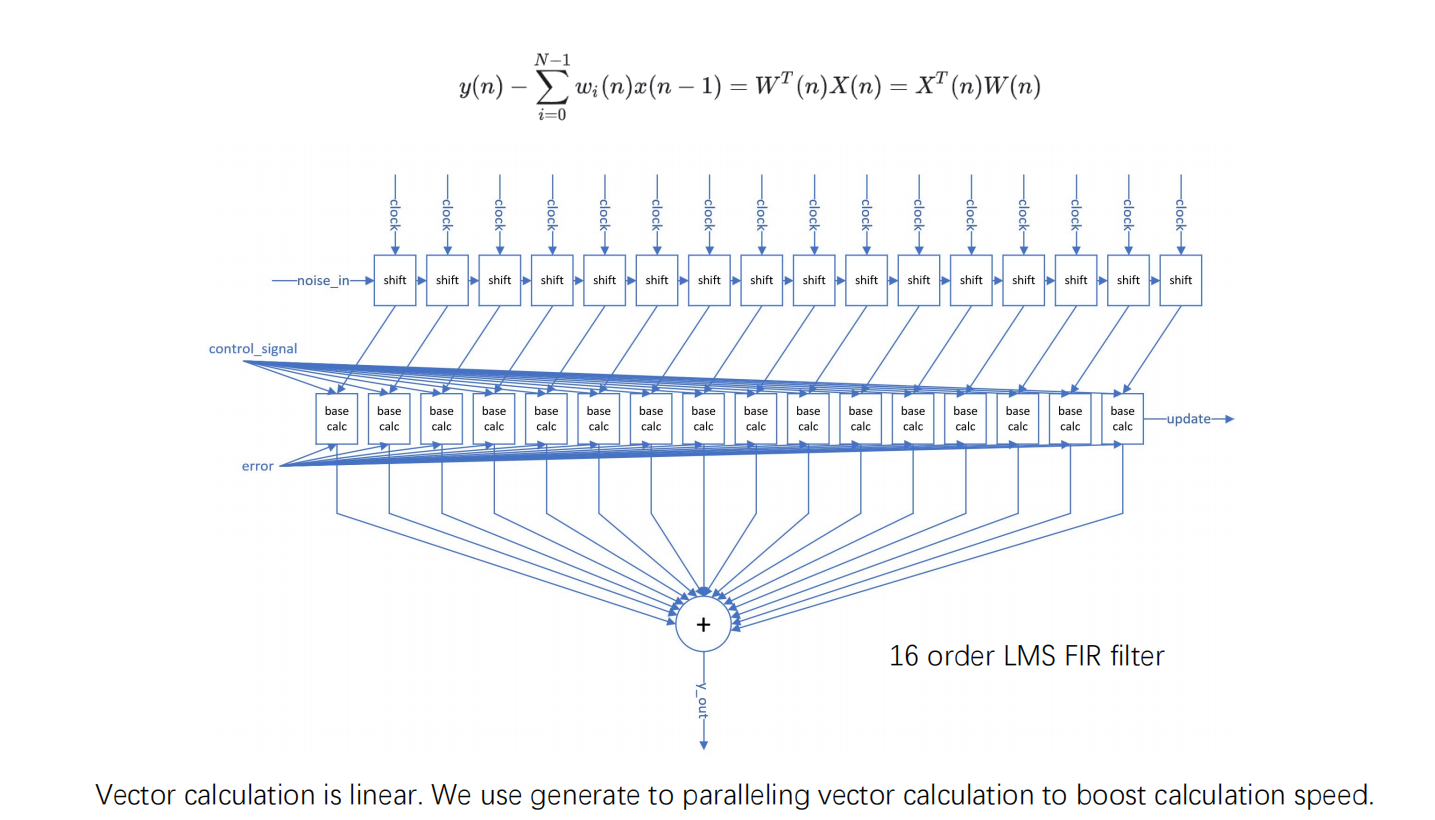
Least Mean Squares (LMS) Filter: The LMS filter is an adaptive filter that aims to minimize the mean square error between a desired signal and the output of a finite impulse response (FIR) filter. It is used in applications like echo cancellation and noise reduction. The filter updates its coefficients by following the equation: w[n+1] = w[n] + μ · e[n] · x[n], where w represents the filter coefficients, μ is the step-size parameter, e[n] is the error between the desired and the actual output, and x[n] is the input signal. Like what is demonstrated in Figure 1.
Infinite Impulse Response (IIR) Filter: IIR filters are digital filters with an impulse response that lasts indefinitely. Their general form is given by: y[n] = Σ (bi · x[n-i]) - Σ (aj · y[n-j]), where x[n] is the input, y[n] is the output, bi are the feedforward coefficients, and aj are the feedback coefficients. IIR filters are efficient in achieving a desired frequency response but require careful design to ensure stability and causality.
Program/hardware design
In this project, our team set out to implement two different noise reduction filters using two distinct algorithms. However, we encountered a significant challenge related to our microphone setup. Initially, our design involved connecting two microphones to the FPGA's line-in using a 2-to-1 connector. Unfortunately, this setup only allowed one of the microphones to function properly. To address this, we attempted to modify the connection by cutting the wires and directly soldering them to the connectors. Despite these efforts, we were still unable to receive input from both microphones simultaneously.
This issue was particularly problematic for our implementation of the Least Mean Squares (LMS) filter, which requires a reference audio channel for effective noise comparison and cancellation. Due to the inability to use both microphones, we were unable to demonstrate the LMS filter physically. Instead, we resorted to using ModelSim to simulate the processing of signal noise, reference noise, and the resulting filtered output. This approach allowed us to validate the conceptual functionality of the LMS algorithm even though we couldn't implement it in a real-world testing environment.
On the other hand, the Infinite Impulse Response (IIR) filter, which we adopted as an alternative to the initially intended FFT-based method, proved to be more adaptable to our hardware constraints. Early in the project, we faced issues with file format conversion when implementing FFT, which ultimately led us to abandon this approach. The IIR filter, however, did not require the dual microphone setup and was able to effectively filter out ambient noise using just a single audio channel. This made it possible to test and demonstrate noise cancellation capabilities effectively in our physical setup.
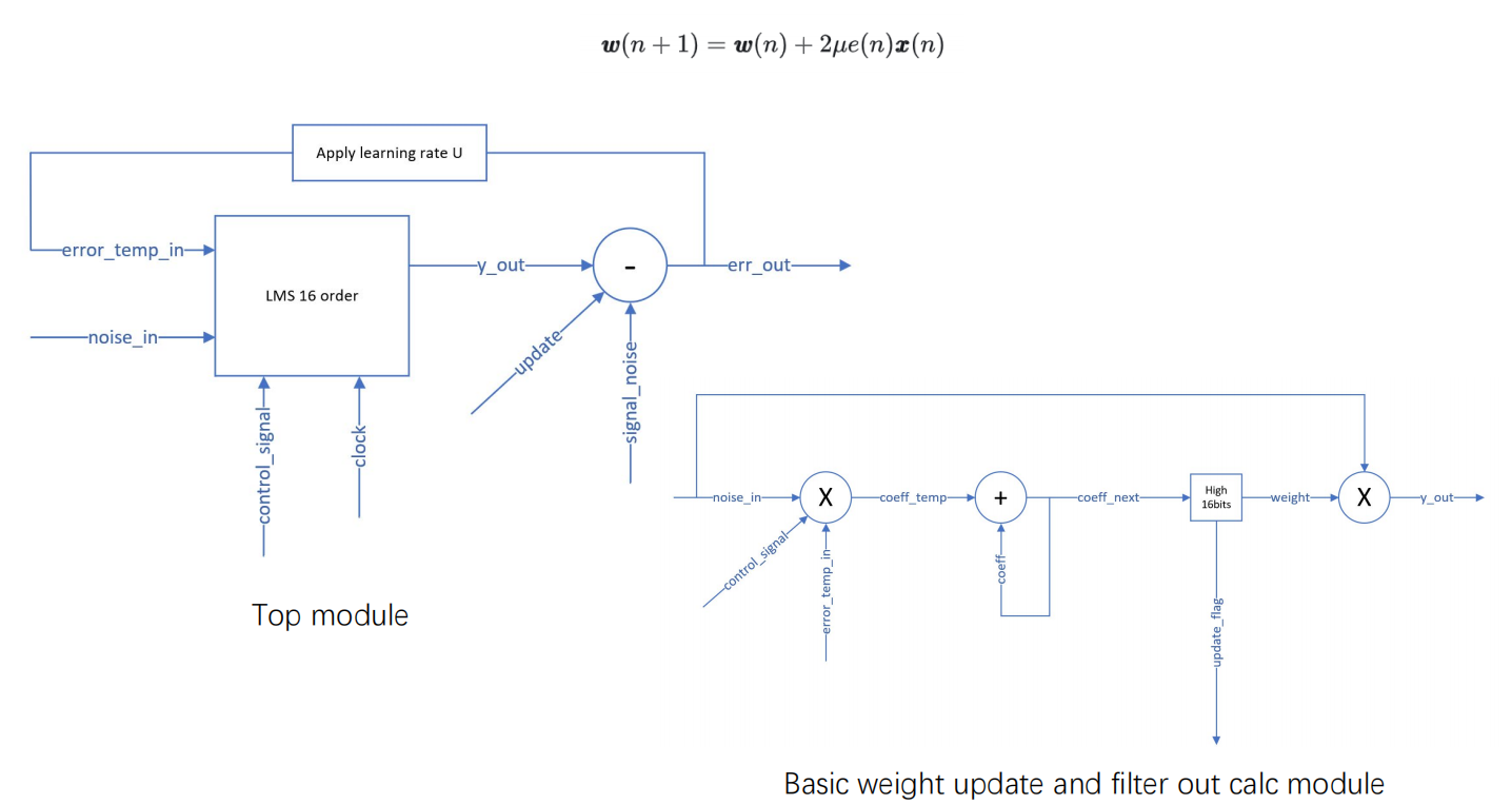
The accompanying diagram (see Figure 2) details the structure of our LMS adaptive filter implementation. It shows how the filter processes input noise signals and adjusts its coefficients dynamically to minimize the output error, illustrating the weight update and filtering calculation modules within our FPGA setup. This visualization helps in understanding the sophisticated nature of the adaptive noise reduction process we developed.
The IIR filter demonstrated excellent noise reduction, significantly enhancing the clarity of the processed audio. This success highlighted the filter's utility in real-world applications where simpler hardware setups are beneficial. Despite the setbacks with the dual microphone configuration and the FFT implementation, the project was valuable in illustrating the practical applications and limitations of different noise reduction techniques within an FPGA environment.
Testing & Result
During the testing phase, as previously demonstrated in the video we mentioned, we evaluated the performance of the IIR filter by speaking into the microphone and observed the noise reduction capabilities of the LMS algorithm through ModelSim simulation. Both algorithms performed exceptionally well in reducing noise.
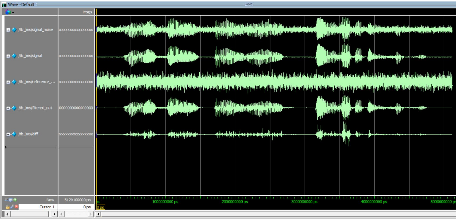
The effectiveness of the LMS noise reduction can be visualized in the signal comparison shown in the following diagram (Fifure 3). This comparison clearly illustrates how the LMS filter dynamically adjusts to minimize the noise in the processed signal, providing a before-and-after perspective on the audio quality improvement.
Conclusion
Our project aimed to develop a robust noise reduction system using FPGA technology, focusing on enhancing voice clarity in various real-world applications. Throughout the course of our work, we implemented two distinct noise reduction techniques: the Least Mean Squares (LMS) adaptive filter and the Infinite Impulse Response (IIR) filter. While we faced significant challenges, particularly in hardware interfacing and algorithm optimization, the results ultimately met most of our expectations. The IIR filter, implemented as a response to the impracticality of FFT due to conversion issues, proved highly effective and exceeded our expectations by performing well with a single-channel input. The LMS filter, although only demonstrable through simulation due to hardware constraints, showed promising results in ModelSim, suggesting its potential efficacy in live environments.
In future projects, one change we would consider is the use of a more flexible and multi-channel capable audio input system to avoid the limitations we faced with the microphone setup. This would allow us to fully implement and test the LMS filter in real-world scenarios, rather than relying solely on simulation.
Information referenced or quoted in this project is indicated in the reference section.
References
lms noise cancellation algorithmIIR noise cancellation algorithm
Audio_core for DE1_SOC
LMS Implementation
Appendix A (permissions)
The group approves this report for inclusion on the course website.
The group approves the video for inclusion on the course youtube channel.
Code Appendix
                //lms testbench
                `timescale 1ns/10ps

                module tb_lms_multi;
                    reg clk;
                    reg rst_n;
                    reg [15:0] reference_noise;
                    reg [15:0] signal_noise;
                    reg [3:0] u;
                    reg [15:0] signal;
                    wire [15:0] filtered_out;
                    reg [15:0] diff;  // Difference between filtered output and original signal

                    // Instance of LMS module
                    lms lms_inst (
                        .clk(clk),
                        .rst_n(rst_n),
                        .en(1'b1),
                        .u(u),
                        .xin(reference_noise),
                        .din(signal_noise),
                        .err(filtered_out)
                    );

                    parameter datalen = 32000;
                    integer k, u_index;

                    // Array to hold stimulus data
                    reg [15:0] stimulus_s [1:datalen];
                    reg [15:0] stimulus_x [1:datalen];
                    reg [15:0] stimulus_d [1:datalen];

                    // Load data from text files
                    initial begin
                        $readmemb("Noise.txt", stimulus_x);
                        $readmemb("Signal_noise.txt", stimulus_d);
                        $readmemb("Original_signal.txt", stimulus_s);
                    end

                    // Main test loop
                    initial begin
                        clk = 0;
                        rst_n = 0;
                        #100;
                        rst_n = 1;

                        for (u_index = 1; u_index <= 15; u_index = u_index + 1) begin
                            u = u_index;
                            reference_noise = 0;
                            signal_noise = 0;
                            signal = 0;
                            #160;  // Allow signals to settle

                            for (k = 1; k <= datalen; k = k + 1) begin
                                reference_noise = stimulus_x[k];
                                signal_noise = stimulus_d[k];
                                signal = stimulus_s[k];
                                #160;  // Update cycle

                                // Calculate the difference between filtered output and original signal
                                diff = signal - filtered_out;
                            end
                        end
                        $finish;
                    end

                    // Clock generation
                    always #10 clk = ~clk;

                endmodule


                // code for lms.v

                module lms #(
	parameter X_W = 16,
	parameter E_W = 16,
	parameter W_W = 16,
	parameter O_N =	16,
	parameter D_W = 16
) (
	input clk,
	input rst_n,
	input en,
	input [7:0] u,
	input signed [X_W-1:0] xin,
	input signed [D_W-1:0] din,
	output reg signed [E_W-1:0] err
);

	reg	signed [E_W-1:0] err_tmp;
	wire en_i;
	reg	signed [D_W-1:0] d_r;
	wire lms_up;
	wire signed [D_W-1:0] lms_yout;
	reg update;

	assign en_i = en;

	lms16_order #(
		.X_W(X_W),
		.E_W(E_W),
		.W_W(W_W),
		.Y_W(D_W)
	) l_inst (
		.clk (clk),
		.rst_n (rst_n),
		.en_i (en_i),
		.xin (xin),
		.err (err_tmp),
		.update (lms_up),
		.yout (lms_yout)
	);

	always @ (posedge clk or negedge rst_n) begin
		if (!rst_n) begin
			update <= 1'b0;
			err <= 'd0;
			d_r <= 'd0;
		end
		else if (lms_up) begin
			update <= 1'b1;
			err <= d_r - lms_yout;
			d_r <= din;
		end
		else begin
			update <= 1'b0;
		end
	end

	always @ (*) begin
		case (u)
			8'd0: err_tmp <= err;
			8'd1: err_tmp <= {err[E_W-1],err[E_W-1:1]};
			8'd2: err_tmp <= {{2{err[E_W-1]}},err[E_W-1:2]};
			8'd3: err_tmp <= {{3{err[E_W-1]}},err[E_W-1:3]};
			8'd4: err_tmp <= {{4{err[E_W-1]}},err[E_W-1:4]};
			8'd5: err_tmp <= {{5{err[E_W-1]}},err[E_W-1:5]};
			8'd6: err_tmp <= {{6{err[E_W-1]}},err[E_W-1:6]};
			8'd7: err_tmp <= {{7{err[E_W-1]}},err[E_W-1:7]};
			8'd8: err_tmp <= {{8{err[E_W-1]}},err[E_W-1:8]};
			8'd9: err_tmp <= {{9{err[E_W-1]}},err[E_W-1:9]};
			8'd10: err_tmp <= {{10{err[E_W-1]}},err[E_W-1:10]};
			8'd11: err_tmp <= {{11{err[E_W-1]}},err[E_W-1:11]};
			8'd12: err_tmp <= {{12{err[E_W-1]}},err[E_W-1:12]};
			8'd13: err_tmp <= {{13{err[E_W-1]}},err[E_W-1:13]};
			8'd14: err_tmp <= {{14{err[E_W-1]}},err[E_W-1:14]};
			8'd15: err_tmp <= {{15{err[E_W-1]}},err[E_W-1:15]};
			default: err_tmp <= err	;
		endcase
	end

endmodule