 |
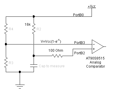
| Figure 1: Capacitance Meter Circuit |
COMATOS has a lot of small details, making it difficult to absorb completely by simply reading the documentation. Perhaps the most useful illustration would be through example.
The system developed in this example is a digital capacitance meter (DCM). It is capable of reading capacitances in the range 1nF~200nF. A measurement is initiated whenever a key is pressed on the keyboard, and the output is sent to the PC through the UART. The circuit used is shown in figure 1. The capacitor to be measured is place in an RC circuit. When the voltage on the capacitor reaches
|
| Figure 1: Capacitance Meter Circuit |
This COMATOS implementation of the DCM is divided into three tasks:
The code file begins with the required include directives for the OS, the interrupt vector table, and constant definitions for the keyboard scan table and output message. Note the inclusion of the required include files:
.nolist
.include "8515def.inc"
; Contains the macro definitions used in the OS, must always be included
.include "comtapi.inc"
.list


; Task Number Definitions
.equ	KbdTask=0
.equ	MeasureTask=1
.equ 	DisplayTask=2
.equ	CapIsr=3

; Measurement State Definitions
.equ 	keyWait 	=0
.equ	dischargeWait	=1
.equ	measureWait	=2


.def	key	=r17	;holds raw press value
.def	butnum	=r18	;final press value
.def	state	=r19	;debounce state
.def	lastKey	=r20	;last keypress
.def	Temp	=r21	;temporary register

.def	capacit =r19	;capacitance value


.equ	waitState=0
.equ	gotKeyState=1

.equ	TIMSKVal=0x08 ; Only use input capture
.equ	TCCR1BVal=0b01000011 ; Capture on rising edge, 64x clock div
.equ	ACSRVal=0b00000111 ; Interrupt enable, rising edge, input capture

.cseg
.org $0000
	rjmp 	RESET	;reset entry vector
	reti
	reti
	rjmp	T1CapISR
	reti
	reti
	reti
	rjmp	OST0ISR ;Timer 0 ISR (MUST ALWAYS BE PRESENT)
	reti
	reti
	rjmp	OSTXISR	;UART buffer empty (MUST ALWAYS BE PRESENT)
	reti
	reti

; Contains the definitions of the subroutines used within the OS,
; including the scheduler, timer 0 ISR, the OS call functions.
; Always included here
.include "comtf.inc"

;Keyboard Scan Table
keytbl: .db 0b11101110, 0b11101101, 0b11101011, 0b11100111
	.db 0b11011110, 0b11011101, 0b11011011, 0b11010111
	.db 0b10111110, 0b10111101, 0b10111011, 0b10110111
	.db 0b01111110, 0b01111101, 0b01111011, 0b01110111

capMessage: .db "The capacitance in nF is:"
As usual, execution begins at the reset interrupt vector. After the stack point is initialized, OSInit must be called. In this case, the timeout counter is set to 30ms, which is the interval between executions of the keyboard task. Next, the relevent I/O registers are initialized to set up input capture, a 64x clock divider on timer 1, and the input/output settings on Port B. Following I/O port initialization, we create the three tasks with OSCreateTask as described in table 1. Note also that instead of passsing absolute addresses for the entry point of each task, we pass labels.
| Table 1: Task Creation Settings | ||
|---|---|---|
| Task | Timeout Condition | Message Mask |
| Keyboard | 30 - Task runs every 30 ms | 0xff - Not using messaging |
| Measurement | 0 - Not using timeout | 0x01 - Initially waiting on task 0 (keyboard) |
| Display | 0 - Not using timeout | 0x02 - Waiting on the measurement task |
RESET:
	ldi	r20, LOW(RAMEND) ;setup stack pointer
	out 	SPL, r20
	ldi	r20, HIGH(RAMEND)
	out	SPH, r20


	OSInit	30, OSDebug		; Specifies 30 ms timeout and debugging features


	; Setup timer 1
	ldi	r16, (TIMSKVal | TimerMask)
	out	TIMSK, r16

	; Setup analog comparator
	ldi	r16, ACSRVal
	out	ACSR, r16


	; Setup PortB for analog comparator
	ldi	r16, 0b11110011 ; Make most pins output except comparator
	out	DDRB, r16
	clr	r16
	out	PORTB, r16	; Start discharging

	OSCreateTask KbdTaskF, 30, 0xff	; Can't run unless timeout since
						; mask is 0xff
	OSCreateTask MeasureTaskF, 0x00, 0x01	; Initially can't run unless
						; it gets a message from the keyboard

	OSCreateTask DisplayTaskF, 0x00, 0x02   ; No timeout, wait for message from measurement
	OSStart					; Run scheduler
halt:	rjmp halt				; Not really necessary
The keyboard task acts as a state machine. During each run (every 30 ms) it uses OSGetState to determine what state it was in before. The task also stores the last key pressed in its own mailbox by sending a message to itself. The state machine works as follows:
; Pulls a key from the keyboard, debounces it, and sends it to the measurement
; task
KbdTaskF:
	OSGetState state	; get the current state

	; Get the key press
	ldi	temp, 0x0f	;set lower four lines to output
	out 	DDRC, temp
	ldi	temp, 0xf0	;and turn on the pullups on the inputs
	out	PORTC, temp
	nop			;Need some time for the pullups to
	nop			;charge the port pins
	nop
	nop
	in	temp, PINC	;read the high nibble
	mov	key, temp	;and store it (with zeros in the low nibble)


 	ldi	temp, 0xf0	;set upper four lines to outputs
	out 	DDRC, temp
	ldi	temp, 0x0f	;and turn on pullups on the inputs
	out	PORTC, temp

	nop			;As before wait for the pin to charge
	nop
	nop
	nop
	in	temp, PINC	;read the low nibble
	or	key, temp	;combine to make key code

	;At the point the raw key code should have exactly one zero each in
	;the lower and upper nibbles. Any other number of zeros indicates
	;either no-button pressed or multiple-button pressed.

	;Now search the table for a match to the raw key code
	;and exit with a button number
	ldi	ZL, low(keytbl*2)	;table pointer in FLASH
	ldi	ZH, high(keytbl*2)	;so convert from word to byte addr
	ldi	butnum, 0

tbllp: 	lpm			;get the table entry
	cp	key, r0		;match?
	breq	foundit
	inc	butnum		;if not, have we exhaused the
	cpi	butnum, 0x10	;table
	breq	illegal
	adiw	ZL, 1		;if not, get the next table entry
	rjmp	tbllp

foundit:subi	butnum, -1	;add one for display
	rjmp	TT1_statematch

illegal:clr	butnum

TT1_statematch:
	OSGetMess	lastKey, 0	;Last key press is stored in our own mailbox
	tst	state			;Check the state
	breq	TT1_state_0
TT1_state_1:
	OSSetState 0		; Return state to zero
	cp	lastKey, butnum	; Compare the key presses
	breq	TT1_debounce	; Key is debounced
	rjmp	TT1_false	; False alarm

TT1_debounce:
	tst	butnum
	breq	TT1_release
	OSSendMess butnum, measureTask; Send the key press to the measurement task
TT1_release:
	OSReturn 0

TT1_state_0:
	cp	lastKey, butnum	; Compare the key presses
	brne	TT1_newKey
	OSReturn 0
TT1_newKey:
	OSSetState gotKeyState ; New key press
	OSSendMess butnum, 0	; Store the last button press
	OSReturn 0
TT1_false:
	OSSetState 0
	OSReturn 0
This task is the meat of the DCM. It acts as a state machine as well, but it uses a different approach from the keyboard task. Instead of storing a state variable using OSSetState/OSGetState, it uses OSSetEntryPt to redefine where execution begins with each successive run. The states are defined as follows:
MeasureTaskF:
	; If we did not get a message from the keyboard
	; something is wrong
	OSGetMessageSrc Temp	; Get the list of who sent us messages
	andi	Temp, exp2(kbdTask)
	brne	MT_startDischarge
	OSReturn 1		;   the keyboard
	; If we're here, the keyboard sent a message
MT_startDischarge:
	sbi	DDRB, 2		; Discharge through analog comp
	cbi	PORTB,2
	ldi	Temp,25
	OSSetTimeout Temp	; Wait 25 ms
	OSSetEntryPt MT_startMeasure  ; Next time we start, we want to pick
	OSReturn 0		      ;  up at the start measurement point


MT_startMeasure:
	cbi	DDRB, 2		; Make pin 2 an input again


	clr	Temp
	out	TCNT1H, Temp	; Clear timer 1
	out	TCNT1L, Temp

	sbi	PORTB, 0	; Raise Vcc to start charging

	ldi	Temp, TCCR1BVal ; Start the timer waiting for charge
	out	TCCR1B, Temp

	OSSetMessMask exp2(CapISR)	; Now we wait on the completion of charging
	clr	Temp
	OSSetTimeout Temp
	OSSetEntryPt	MT_finishMeasure  ; Next time we start, we will be at
	OSReturn 0			  ; the measurement handling code

	;If we're here, the correct value is in the capture register
MT_finishMeasure:
	OSGetMessageSrc Temp 	; Get the list of who sent us messages
	andi	Temp, exp2(capISR) ; If the capture ISR did not send it
	brne	MT_fM1
	OSReturn 1		; something's wrong, so return bad error code
MT_fM1:
	clr	Temp
	out	TCCR1B, Temp	; Shut off timer 1
	cbi	PORTB, 0	; Drop Vcc to discharge capacitor

	in	Temp, ICR1L ; Grab the capacitance value


	OSSendMess Temp, DisplayTask ; Send the value off to be displayed
	OSSetMessMask exp2(KbdTask) ; Wait for the next key press
	OSSetEntryPt MeasureTaskF   ; Start from the beginning next time
	OSReturn 0		; Done
Display Task
The job of this task is to send the capacitance message to the UART. First, it copies the message from the program memory to the SRAM, since that is where OSUARTWait needs it to be. It sets the character count and begins transmission. The final step is to format the value of the capacitance as ASCII characters instead of a hexadecimal number, and then display that to the UART.
DisplayTaskF:
	; If we're here, there's a capacitance to print
	ldi	ZL, low(capMessage*2)	; Point to the first character
	ldi	ZH, high(capMessage*2)  ; of the output string

	ldi	Temp, 26
	sts	OSBase+OSUARTCharCnt, Temp	; Tell the UART to 26 characters

	ldi	YL, low(USRBase)		; Point at the beginning of memory
	ldi	YH, high(USRBase)

DT_0:	; Copy from program memory to SRAM
	lpm
	adiw	ZL,1
	st	Y+,r0
	dec	Temp
	brne	DT_0

	; Aim Z at the output string
	ldi	ZL, low(USRBase)
	ldi	ZH, high(USRBase)

	lds	Temp, OSBase+OSStatus
	cbr	Temp, exp2(txdone)	; Clear the bit indicating txdone
	sts	OSBase+OSStatus, Temp


	ld	Temp, Z+	; Put the first character in Temp
	OSUARTWait Temp		; Send the message

	; Now send the capacitance value itself
	OSGetMess Capacit, MeasureTask

	; Format the string
	ldi	ZL, low(USRBase)
	ldi	ZH, high(USRBase)
	clr	Temp
DT_1:	cpi	Capacit, 100
	brlo	DT_tens
	subi	Capacit, 100
	inc	Temp
	rjmp	DT_1
DT_tens:
	subi	Temp, -ascii0
	st	Z+, Temp
	clr	Temp
DT_2:
	cpi	Capacit, 10
	brlo	DT_ones
	subi	Capacit, 10
	inc	Temp
	rjmp	DT_2
DT_ones:
	subi	Temp, -ascii0
	st	Z+, Temp
	subi	Capacit, -ascii0
	st	Z+, Capacit
	ldi	Temp, 0x0d	; Newline character
	st	Z, Temp
; We've done the conversion, now send the value
	ldi	ZH, high(USRBase)
	ldi	ZL, low(USRBase)

	ldi	Temp, 4
	sts	OSBase+OSUARTCharCnt, Temp	; Tell the UART to 3 characters

	ld	Temp, Z+	; Put the first character in Temp
	OSUARTWait Temp

	OSReturn 0
Capture ISR
Like any ISR, the capture ISR is intentionally kept short. It simply sends a message to the measurement task using ISRSendMess. This message does not contain any data and simply makes the measurement task eligible to run again.
; Analog comparator capture complete
; Capacitance in nF is in capture low register
T1CapISR:
	push	Temp
	push	Capacit
	in	Temp, SREG
	push	Temp
	ISRSendMess Temp, measureTask, CapISR ; Send a message to the measurement
					      ; task signalling the available value
	pop	Temp
	out	SREG, Temp
	pop	Capacit
	pop	Temp
	reti
This example leaves some room for optimization. For example, the ISR could send a message directly to the display task, completely eliminating the measurement task from the last step. Likewise, using OSSetEntryPt to develop state machines tends to involve simpler logic than using OSSetState/OSGetState. Please feel free to experiment with this example, which can be found in the source code section of this document.