VitalCam: Wireless
Telemetry and the Internet
Shaun Chandran
May 3, 2001
Neurobiology Honors
Abstract
The fruit of one and a half years of work exploring the area of biological telemetry is a new breed of medical telemetry device, entitled the VitalCam. During my first semester of research, I focused on the development of BioSignals, which was written in Matlab to analyze and display waveforms produced by Cleveland Medical Systems’ BioRadio, a medical telemetry device. After creating BioSignals, I recognized that I could build a better telemetry device by employing wireless Ethernet technology. Employing this idea, my partner Benjamin Greenblatt and I developed the VitalCam to take advantage of the scalability of both wireless Ethernet and the Internet. I focused on the development of the software for the VitalCam, which includes adding Internet functionality to BioSignals, while my partner focused on the development of the VitalCam’s hardware. Due to its small size and weight, the VitalCam appeared to have wide biological applications since it could be easily attached to either human or animal subjects without restricting the subject’s movement.
Introduction
Today, almost every industry employs telemetry devices to retrieve data remotely. Fundamentally, telemetry involves the acquisition of data from a source and the subsequent transmission to a different location. As such, telemetric devices can be decomposed into a transducer and transmission module. The transducer obtains data, and the transmission module relates the data to a computer at another location. From aerospace to medicine, telemetric devices provide vital data.
In 1912, the first telemetry systems were created to monitor electric power distribution. Later in the 1930s, the aerospace industry employed telemetry with the radiosonde, a device that measures meteorological data. (Telemetry 2001) In the late 1950s and early 1960s, wired medical telemetry devices became integrated with the appearance of the first intensive care units in New York at Montefiore Hospital in 1959. (Stringer 2001) With the advent of wireless technologies, telemetric devices gained mobility by utilizing radio frequencies to transmit data over great distances.
During the spring semester of 2000, Benjamin Greenblatt and I began work on a software package for Cleveland Medical Systems’ BioRadio. The BioRadio employs packet-radio technology to transmit data wirelessly from a human or animal subject to the computer. BioSignals, the data acquisition computer application that we created, empowers researchers to acquire data with the BioRadio through Matlab, a commercial mathematics package. After developing BioSignals, we realized that a more substantial and more interoperable telemetric device could be built. Compared to our device, tentatively named VitalCam, the BioRadio is limited by both its transmission technique and its transducers.
The VitalCam improves upon the BioRadio in both data acquisition and transmission. Employing improved analog to digital circuitry, the VitalCam, unlike the BioRadio, can have its gain on any of its eight channels changed dynamically via software. In data transmission, the VitalCam benefits from its use of wireless Ethernet, specifically the 802.llb standard. With packet-radio technology, the BioRadio had limited bandwidth to transmit data. This limited bandwidth, 0.064 MBps, translates into significant limitations for sampling rates. With a potential of 11 MBps of bandwidth, wireless Ethernet offers the VitalCam the potential to transmit a maximum of 172 times the data of the BioRadio from its multiple channels. In addition, VitalCam takes advantage of Internet protocols to transmit data.
Unlike current telemetry devices, the VitalCam empowers a researcher or
physician to give his subject greater freedom.
Due to the versatility of the 802.llb standard, VitalCam can reduce its
bandwidth consumption in order to increase its range dramatically. This allows a subject up to 500 feet of
freedom from the nearest receiver. In the figure 1, a subject is attached to
the VitalCam, and the device automatically establishes a connection with and
transmits data to a remote computer.
Due to the architecture of wireless Ethernet, multiple receivers in
different locations can vastly extend the range of the device.
The incorporation of Internet protocols into the data transmission module of the VitalCam differentiates it from other devices. Wireless Ethernet allows the subject not to be tethered to a researcher’s computer. The incorporation of the UDP Internet protocol allows a researcher to retrieve his data from any computer connected to the Internet. Specifically, a computer that receives the data from the VitalCam does not necessarily have to be the same computer that researcher employs to view the data. To access data from the VitalCam, a researcher will be able to launch BioSignals from an Internet-ready computer. BioSignals will be able to contact the VitalCam over the Internet to initiate a data stream from a subject.
There are many benefits that researchers can reap from the integration of wireless Ethernet and Internet protocols in the VitalCam. For animals, researchers will benefit from more realistic data than can be obtained by allowing their subjects to roam freely. Similarly, researchers will be able to allow subjects of sleep studies to go home to sleep. Cardiologists will be able to employ the VitalCam in place of a halter monitor because patients can transmit heart waveforms in real time to their physicians. Since the VitalCam employs Internet standards, researchers and physicians will be able to share data in a transparent fashion. Multiple researchers at different locations will be able to view real-time data from subjects. Physicians will be able to share live data with other physicians in different parts of the country.
The VitalCam has a robust set of features, which gives it great utility for a number of different applications. Like the BioRadio, the VitalCam is capable of generating an electroencephalograph, electromyogram, or an electrocardiogram. Paramedics will be able to use this device in order to share vital statistics of patients at the scene with doctors and nurses waiting at the hospital. With this critical information at the hospital, physicians can get an accurate picture of the patient’s status and potentially be able to offer paramedics suggestions on how they can help ameliorate a patient’s condition en route.
Currently, the VitalCam has two channels with the potential for having a total of eight channels. Because of the immense bandwidth of wireless Ethernet, it can sample at a maximum of 8 kHz for all of its channels. Hence, the prototype of the VitalCam can sample at 4 kHz/channel for each of its two channels. Also, the improved analog to digital circuitry will allow a user to change the gain on an individual channel on the fly without pausing the data stream. By comparison, the BioRadio has eight channels with a maximum sampling rate of 160 Hz/channel. With a larger sampling rate, many filters may be applied dynamically without severe signal degradation. Although wireless Ethernet provides the bandwidth to transmit far higher sampling rates, e.g. 27 kHz, there are several limiting factors that prevent the higher sampling rates. Firstly, the onboard analog to digital circuitry is incapable of taking samples reliably above 8 kHz rate, and the Atmel processor would not be able to handle reliably the work of retrieving the samples, forming data packets, and transmitting them through the Ethernet card at higher sampling rates.
 The
VitalCam’s design is extremely versatile.
With the additional bandwidth afforded by wireless Ethernet, one of the
channels for acquiring heart or brain wave data can be employed for acquiring
sound data. Few modifications are
required so that other modules, such as a microphone, can be incorporated so
that a greater breadth of data can be acquired from a subject. If a more
powerful processor is incorporated into the device, even video data could be
transmitted simultaneously with a subject’s vital statistics since the device
will be handle a data throughput beyond 8,000 bytes/sec, which is its current
maximum due to the speed of the Atmel processor. The incorporation of new data
transmission technologies in the VitalCam empowers researchers to share and
distribute data that they acquire.
The
VitalCam’s design is extremely versatile.
With the additional bandwidth afforded by wireless Ethernet, one of the
channels for acquiring heart or brain wave data can be employed for acquiring
sound data. Few modifications are
required so that other modules, such as a microphone, can be incorporated so
that a greater breadth of data can be acquired from a subject. If a more
powerful processor is incorporated into the device, even video data could be
transmitted simultaneously with a subject’s vital statistics since the device
will be handle a data throughput beyond 8,000 bytes/sec, which is its current
maximum due to the speed of the Atmel processor. The incorporation of new data
transmission technologies in the VitalCam empowers researchers to share and
distribute data that they acquire.
The VitalCam aids
not only researchers but also its subjects.
It will give patients mobility to leave the hospital and obtain care
remotely due to its size. Currently,
the circuitry for the VitalCam occupies the space of a board ![]() in width and height
and
in width and height
and ![]() ²
in thickness, and the entire apparatus weighs approximately 14 oz as seen in
figure 2. Stacking the analog to
digital board behind the board carrying the Cisco wireless Ethernet card can
reduce the size of this prototype. There is a significant capacity to reduce
the footprint of the analog to digital circuitry as well as the circuitry
controlling the wireless Ethernet. With
the size of wireless Ethernet modules decreasing, the VitalCam will be able to
shrink in size. For researchers, the
decreased size will mean that smaller subjects, such as eagles, can be
monitored. For patients, the monitors’
small size allows it to be inconspicuous and not inhibit a patient’s
activities. Physicians will constantly
be apprised of a patient’s situation since the VitalCam will be continually
transmitting to them data over the Internet. In 1991, when the Medical Data
Electronics introduced one of the first wireless telemetry devices, wireless
telemetry appeared as novelty and not as a necessity. (Gardner 1991) Wireless
data transmission for this device did not exceed 0.0096 MBps, and consequently,
this device could only monitor vital statistics wirelessly. To perform ECGs, this telemetric device had
to be connected to a hospital’s network. (Gardner 1991) In recent years, the
advent of wireless telemetry has revolutionized how researchers and physicians
conduct tests on their subjects. The
VitalCam allows a researcher to obtain data from animal subjects in their
native habitats. Similarly, physicians
can monitor patients of sleep studies at their homes. In the following sections, we will discuss specifically how the
VitalCam was designed and show a sample instance in where it acquired data.
²
in thickness, and the entire apparatus weighs approximately 14 oz as seen in
figure 2. Stacking the analog to
digital board behind the board carrying the Cisco wireless Ethernet card can
reduce the size of this prototype. There is a significant capacity to reduce
the footprint of the analog to digital circuitry as well as the circuitry
controlling the wireless Ethernet. With
the size of wireless Ethernet modules decreasing, the VitalCam will be able to
shrink in size. For researchers, the
decreased size will mean that smaller subjects, such as eagles, can be
monitored. For patients, the monitors’
small size allows it to be inconspicuous and not inhibit a patient’s
activities. Physicians will constantly
be apprised of a patient’s situation since the VitalCam will be continually
transmitting to them data over the Internet. In 1991, when the Medical Data
Electronics introduced one of the first wireless telemetry devices, wireless
telemetry appeared as novelty and not as a necessity. (Gardner 1991) Wireless
data transmission for this device did not exceed 0.0096 MBps, and consequently,
this device could only monitor vital statistics wirelessly. To perform ECGs, this telemetric device had
to be connected to a hospital’s network. (Gardner 1991) In recent years, the
advent of wireless telemetry has revolutionized how researchers and physicians
conduct tests on their subjects. The
VitalCam allows a researcher to obtain data from animal subjects in their
native habitats. Similarly, physicians
can monitor patients of sleep studies at their homes. In the following sections, we will discuss specifically how the
VitalCam was designed and show a sample instance in where it acquired data.
In
my research, I worked primarily with my partner, Benjamin Greenblatt. As an electrical engineer, Benjamin was
primarily responsible for the hardware component of the VitalCam. My primary responsibility was develop
network software tools that would not only simulate the behavior of the
VitalCam, but also receive data from the VitalCam that would imported into the
BioSignals Matlab application for both viewing and manipulation.
Materials and Methods
Figure 3 is a flow chart depicting the different components of this project. This section of the paper will discuss how the hardware portion of the VitalCam project functions. The hardware portion of the VitalCam includes three components: an analog module, the Atmel processor module, and wireless Ethernet module. With these three components, data is acquired from a subject and transmitted over the Internet to a remote computer.
Analog Module
The analog module of the VitalCam is responsible for retrieving data from a subject. In particular, as a medical telemetry device, the analog component measures electrical activity in a subject. For example, when a physician performs electromyography, he measures the action potentials of muscle tissue by placing the leads of the VitalCam in the general vicinity of the muscle tissue that is being studied. In addition to leads, amplifiers and filters form essential parts of the analog module of this device. The VitalCam has a total possible number of 8 leads or channels, but in the current design, only two channels are implemented. When an electrical current is conducted by a lead, it passes through an amplifier. Since the voltage being measured is extremely small, in the order of electron volts, the VitalCam employs amplifiers to increase the gain of the signal to detectable levels. The amplifiers also serve the function of reducing electrical noise. When the leads conduct electrical activity from a subject, they also may conduct electrical activity from the environment. Fluorescent lighting, cordless phones, radios, and other electrical devices produce electrical noise that might interfere with obtaining accurate readings from a subject. Amplifiers not only amplify a signal but also filter out background electrical noise. Finally, low pass filters are also employed in the analog module. A low pass filter eliminates high frequencies from a signal and allows low frequencies to pass. A low pass filter is an important part of the analog end of the VitalCam because it serves to antialias a signal.
Aliasing occurs because the VitalCam takes samples of a signal, and if the frequency that is being measured is too high, aliasing occurs and creates an inaccurate signal. According to Nyquist’s Theorem, in order to accurately sample a signal, the sampling rate, the frequency of measurements, must be at least twice the frequency of a signal. High frequencies are those frequencies that cannot be sampled accurately according to Nyquist’s Theorem. If a low pass filter were not included in the VitalCam, then these high frequencies would appear as low frequencies, and consequently, there would be aliasing.
Each component of the analog portion of the VitalCam performs an essential function in acquiring data from a subject. The leads detect electrical activity while amplifiers boost the signal and reduce noise. Lastly, the low pass filter ensures that the final output signal does not contain erroneous frequencies that are produced due to aliasing.
Atmel Processor Module
The heart of the VitalCam is the Atmel processor module. Atmel’s ATMEGA 103/L processor is linked to all the hardware components of the VitalCam. For instance, the analog module and the wireless Ethernet card are linked to the processor. The Atmel manages data entering through the analog module and prepares this data for transmission through the wireless Ethernet card. This module can be further decomposed into the analog to digital converter and the Atmel processor. These components serve different functions in the device.
The analog to digital (A/D) converter is the component of the processor module that links the Atmel to the analog module. With the signal input provided by the analog module, the A/D converter takes a sample of this signal by associating a value to the signal at the moment that the signal is sampled. The A/D converter essentially creates digital values representing the analog signal. Consequently, the A/D converter is responsible for providing the Atmel with values representing the samples of a particular signal coming through any of its channels.
The Atmel has several functions in the VitalCam. It is accountable for formatting incoming data from the A/D converter, and due to its link to the wireless Ethernet card, the Atmel is responsible for preparing the Ethernet device for data transmission. Since the VitalCam uses the Ethernet card to transmit data over the Internet, the Atmel must also be responsible for formatting data from the A/D converter for the Internet.
When the VitalCam is first turned on, the Atmel initializes the wireless Ethernet card. Then, the Atmel reads in configuration data from its flash memory, which tells it what channels are active and how much bandwidth is to be used. At any moment, the Atmel takes only 400 samples from all active channels, so in order to control the bandwidth consumed, the number of times per second 400 samples are taken is varied. Since only two channels are currently supported at 4 kHz/channel, the Atmel is preprogrammed to retrieve 400 samples from two channels every twentieth of a second. For details about the VitalCam configurations, refer to the appendix. In summary, after initializing the wireless Ethernet card, the VitalCam begins to take samples from the A/D converter.
When 400 samples have been taken, the Atmel generates a packet for transmission. There are two packets formed by the Atmel: an internal packet and a UDP (User Datagram Protocol) packet. UDP is an Internet protocol that is employed to transmit data packets on the Internet. In summary, the Atmel creates an internal packet with all the data it needs to transmit to a remote computer, and then it takes this internal packet and puts in a UDP packet for transmission onto the Internet through the wireless Ethernet card.
The VitalCam creates a packet through two tiers of code. The internal packet format of the VitalCam is organized through a structure that has fields for device ID, packet number, bandwidth, channel, and data array. The device ID acts an identifier for the VitalCam; each VitalCam will have a different device ID so that more than one VitalCam operate on a network at the same time. The packet number allows the remote computer to identify the order in which packets are received. Both bandwidth and channel fields provide configuration information where bandwidth reports the total sampling rate and channel contains binary information regarding which channels are active. As soon as the VitalCam acquires data from the analog to digital component, it stores acquired data in the format specified in the appendix in a 400-byte data field, where 1 byte is one sample.
Once the data packet, containing the fields described above, is created, the complete UDP packet has to be formed. To form the entire UDP packet, IP header must be wrapped around the packet. This IP header contains the destination and source IP addresses. In addition to this header, the UDP packet contains the Media Access Control (MAC) address of the source computer’s network card and a checksum. The Atmel computes a checksum for the packet based on the packet’s contents as well as some of the IP header. The remote computer verifies the validity of incoming packets using the checksum. Once the UDP packet is fully formed, it is passed to the wireless Ethernet module for transmission.
Wireless Ethernet Module
The wireless Ethernet Module is responsible for data transmission to the Internet. The wireless Ethernet card, Cisco’s Aironet 340 Series PC card, connects to the Atmel with a personal memory card international association (PCMCIA) interface. The Aironet card employs PCMCIA interface to connect the Atmel. By following the 802.llb standard, the Aironet card handles all wireless communication to either a remote computer or wireless Ethernet hub. After receiving initialization commands from the Atmel, the Aironet card attempts to associate with either another computer with a wireless Ethernet card or a wireless Ethernet hub. This association process connects the wireless Ethernet card onto the network. After the detecting that the Aironet card is associated with the network, the Atmel begins to fill the Aironet card’s buffer with a UDP packet. Once the packet is completely in the Aironet’s buffer, the Atmel activates the transmit line in the PCMCIA interface to let the Aironet card know to transmit the packet onto the network. At the same time, the Atmel checks the Aironet card to see if the Aironet card has received a packet. In this event, the Atmel empties Aironet card buffer and processes the incoming packet.
Aside
for transmitting UDP packets, the wireless Ethernet card can receive packets
that correspond to ping, ARP (Address Resolution Protocol) requests, and
BioSignals configuration packets. Ping
is a program that allows a remote computer to detect if a particular computer
or device, such as the VitalCam, is on the network. ARP requests are employed in the transmission of packets. In many Internet protocols, an ARP request
is issued to a remote device before a data is sent to it in order to ensure
that the destination device is on the network.
Finally, BioSignals, the application that receives data from the
VitalCam, can reconfigure the VitalCam’s channel, bandwidth, and Internet
settings through a configuration packet. (Refer to appendix) The wireless
Ethernet card receives these packets, and the Atmel processes these packets and
sends the appropriate packets to respond to these requests.
Results
In this section of the paper, the second half of the above flow chart and few development applications will be discussed. The majority of my efforts in this research project were dedicated to the receiving end of the data transmitted by the VitalCam. On the remote computer side of the flow chart, there are three primary components involved in displaying the measurements taken by the VitalCam. They are the remote computer’s wireless Ethernet card, Microsoft Windows Network Services, and the BioSignals application. Utilizing these components, data from the VitalCam was retrieved and displayed on the remote computer’s monitor. In supplement to the discussion of these components, the VitalCam Simulator and Server applications will be elaborated on how they aided in the development of the VitalCam.
Remote Wireless Ethernet Card
In the current setup of the VitalCam, the VitalCam’s wireless Ethernet card associates with the remote computer’s wireless Ethernet card. Subsequently, the VitalCam transmits user datagram protocol (UDP) packets to the remote computer’s wireless Ethernet card. Once the network card receives a packet in its buffer, the network card notifies Windows Networking Services that the data is in the network card’s receive buffer. At this point, Windows Networking Services empties the buffer of data containing the UDP packet from the VitalCam. The wireless Ethernet card is responsible for all communication to the VitalCam. The VitalCam Simulator, VitalCam Server, BioSignals and other network test applications rely on the remote computer’s Ethernet card for transmitting and receiving data.
Microsoft Windows Networking Services
Since packets that are being transmitted from the VitalCam adhere to the UDP Internet standard, the remote computer, running any version of Microsoft Windows, receiving the UDP packets via the wireless Ethernet card must have the TCP/IP (Transmission Control Protocol/Internet Protocol) networking services installed. This layer of networking services serves an integral purpose in receiving data from the VitalCam. The UDP protocol exists within the TCP/IP protocol. When the Ethernet card receives a UDP packet, Windows Networking Services is notified, and specifically the TCP/IP network layer takes the UDP packet and passes a socket, as seen in the flow chart, to any application running on the computer that wishes to read the data from this packet. In preparing the data socket, the network services independently computes a checksum for the packet and verifies it against the checksum that is already in the UDP packet. If both of the checksums are the same, then the remainder of the UDP layer on the data is removed, and a socket is created pointing to this now unwrapped packet. Incidentally, the unwrapped packet is identical to the internal packet that the VitalCam generates in the process of making a UDP packet. In review, the Windows Networking Services verifies if an incoming UDP packet is valid by corroborating the packet’s checksum with a computed checksum and releases a socket pointing to a packet without the UDP layer to BioSignals through Matlab, an application running on Windows.
BioSignals
In the spring of 2000, BioSignals was originally created for Matlab 5.3 in order to view and to perform signal analysis on data coming from another medical telemetry device, Cleveland Medical System’s BioRadio. As mentioned earlier, the BioRadio and the VitalCam both provide telemetry data, so BioSignals was modified to include Internet functionality so that it too could work with the VitalCam. BioSignals was built on Matlab, so BioSignals can only be launched from the Matlab command window. All the functions used to build the graphical interface, to plot the data, to perform signal analysis, and to interface with Windows Networking Services are executed in Matlab for the BioSignals application. By employing internal Matlab functions as well as custom-built functions, BioSignals acquires data from the Windows Networking Services and displays the data in its windows by using Matlab’s plot command.
BioSignals initiates this process of acquiring data from Windows Networking Services by using the getvframe function. (Refer to appendix for code) Since there currently is only one configuration for the VitalCam, where it transmits 400 samples every twentieth of a second, BioSignals calls the getvframe function every twentieth of a second by using the timer function from Matlab’s data acquisition toolkit. In its present version, BioSignals can receive data from one VitalCam at a time. The getvframe function is responsible for creating a network socket that is linked to the data received by Windows Networking Services. The getvframe function takes the received datagram and points it to a structure, called RecPacket. The RecPacket structure allows the getvframe function to access all the relevant data fields within the packet. With the RecPacket, the received datagram is parsed into Matlab variables that are returned to the BioSignals application. As seen in the appendix, the getvframe function returns the channels that are active, the bandwidth, data array organized according to active channels, packet number, the total number of lost and out of sequence packets, an error variable, and the handle to the network socket.
Since the UDP Internet protocol does not handle error detection, an error correction algorithm was written. For this reason, the values for packet number, lost packets, and out of sequence packets were maintained. Unlike TCP/IP, the mainstream Internet protocol, UDP does not guarantee that the remote computer receives every transmitted packet. Despite this important disadvantage, UDP is employed because of the speed benefits. Integrating TCP/IP into the VitalCam would add an additional level of complexity. In our first attempt to build the network component of the VitalCam, we included Seiko’s I-chip for TCP/IP functionality, but the I-chip reduced the VitalCam’s throughput in half to 4 kHz of bandwidth. Due to the increased complexity and bandwidth required by TCP, UDP was selected to be the Internet protocol implemented by the VitalCam.
The error correction algorithm handles several possible error conditions to ensure that the data received is valid. For this reason, the getvframe executes the error correction algorithm on every incoming packet. A valid packet is a datagram that has a packet number greater than the last received packet. If the packet received has a packet number less than or equal to the last received packet, then this packet is deemed unusable and the error variable is set to 1 indicating that an error has occurred. This error correction algorithm ensures that displayed data is shown and recorded in chronological order. In order to keep track of lost packets and out of sequence packets, the error correction algorithm maintains these statistics while observing the packet numbers of incoming packets.

BioSignals supports the remote
configuration of the VitalCam through the setup menu. The setup menu for the VitalCam employs another custom function,
sendconfig, to change the channel, bandwidth, and Internet settings of the
device. (See appendix for code) The working prototype of the device responds to
a configuration packet containing information regarding the VitalCam’s various
settings, including active channels, bandwidth, gateway IP address, destination
IP address, and gains. Note that the prototype does not implement variable gain
on any of the channels, so modifying the gain values does not change the signal
that the device sends to the remote computer. Upon pressing the “ok” button
from the setup menu, BioSignals verifies if there are any changes to the
VitalCam’s configuration. If there are changes, BioSignals calls the sendconfig
command with the updated settings, and sendconfig transmits a UDP configuration
packet to the VitalCam, which changes the VitalCam’s configuration. Then, BioSignals verifies that the VitalCam
made the configuration changes and closes the setup menu. The purpose of changing the gateway IP
address and destination IP address for the VitalCam involves programming the
device to transmit to another computer not on the local wireless network but
over the Internet. The gateway IP
address is the intermediary computer through which the VitalCam will transmit
data to the computer with the destination IP address anywhere on the Internet
as seen in figure 5 on the previous page.
Aside from the addition of the getvframe and sendconfig function, BioSignals remains largely unchanged from its previous revision. The graphical interface of BioSignals takes advantage of the user interface tools provided by Matlab. Through the graphical interface, BioSignals allows a user to open, save, and capture data. In the file menu, there is an open, save, export to audio, print, and setup dialogs. The open menu allows a user to view previously captured data, while the save menu allows recently captured data to be recorded. The export to audio function enables a user to create a separate sound file for each channel that BioSignals is monitoring. The print menu is a simple tool that allows a user to print the waveforms that are currently displayed on the screen. The setup menu currently allows the user to input the configuration of the BioRadio or the VitalCam. As mentioned above, reconfiguring the VitalCam would involve sending UDP configuration packets to the device after the user clicks on the “ok” button in the setup menu until the configuration data of packets sent by the VitalCam to the computer running BioSignals matches the configuration setup in the BioSignals application.
Additional top-level menus include the edit, tools, view, and help menus. The edit menu allows the user to export a screen copy of the waveforms being displayed. From the tools menu, a signal-processing dialog can be accessed. This dialog box allows the user to select specific channels to apply high and low pass filters and Fourier transform (FFT). The view menu gives the user the option of choosing which channels should be displayed in the main window. Finally, the help menu gives the user access to online help and version information regarding BioSignals.
Lastly, there are start and stop capture buttons and y-scale pull down menus. The start capture button enables the user of BioSignals to view real-time measurements coming from the VitalCam plotted in the main window, as seen in the BioSignals help section in the appendix. The stop capture button stops BioSignals from plotting new data that is being transmitted from the VitalCam. The y-scale pull down menus are for each of the eight channels adjusting the scaling of the waveforms. At the bottom left hand side of the application, the user can select if BioSignals will be used with the BioRadio or the VitalCam through a radio button.
VitalCam Simulator and Server
The VitalCam Simulator is an application that was created to simulate the behavior of the VitalCam. This application that runs on, disk operating system (DOS), employs windows network sockets to output UDP packets to a target computer. Employing the internal packet structure of the VitalCam, this simulator produces packets that are identical except for the packet number. The packet number is incremented so that the server software, BioSignals or UDPs (discussed later), can detect if packets are coming in out of sequence or are being lost. To execute the VitalCam simulator, the program (UDPc.exe) must be executed in a dos window with the “-n” and the IP address of the destination computer. In addition to building a simulator for the VitalCam, another server software application was constructed to test packets coming from the prototypes of the VitalCam. This server software allowed us to debug the VitalCam. This VitalCam server software, titled UDPs, receives packets, and outputs the contents of these packets. The getvframe function discussed before shares code with UDPs. Notably, the error correction algorithm for both applications is the same. When UDPs starts, the user specifies an information interval. This information interval is the number of packets that must be received before packet statistics and the contents of the next incoming packet are displayed. The source files and screenshots for the simulator and the server application is included in the appendix.
Conclusion
Unlike other telemetry devices employed in research, the VitalCam takes advantage of the Internet. From hardware to software, the VitalCam incorporates Internet technologies that benefit biological research. During the development of BioSignals, the limitations of current telemetry systems, such as Cleveland System’s BioRadio, became readily apparent.
The VitalCam offers researchers the opportunity to give their subjects greater liberty to move around. Due to the design of the wireless Ethernet standard 802.llb, biologists can strategically setup wireless Ethernet hubs around an animal’s habitat to maximize the coverage area. Since wireless Ethernet has a maximum range of 500 feet in open areas, researchers will be able to perform a variety of experiments previously impossible. For instance, the BioRadio, which employs a packet radio technology, has a maximum range of 50-75 feet. With the VitalCam, researchers can observe remotely animal subjects. By combining wireless Ethernet with UDP packet transmission, researchers need not be in the same country to study live data coming from a subject.
VitalCam has another key advantage, additional bandwidth, over competing devices, such as the BioRadio, due to its use of wireless Ethernet. The additional bandwidth offered by wireless Ethernet give the VitalCam ability to sample each channel at higher rates. According to Nyquist’s Theorem as previously discussed, for accurate signal reconstruction, the sampling frequency must be at least twice the maximum frequency of a sample signal. In many applications, a researcher may be unaware of the maximum frequency of the signal that is being observed. In such cases, a high sample rate is preferable to ensure that aliasing does not occur when the signal is reconstructed. When a high frequency signal is sampled at less than twice the signal’s maximum frequency, the high frequency signal may be reconstructed as a low frequency signal since there are insufficient samples to resolve the high frequency of the signal. For EKG, EMG, and EEG tests where the maximum frequency of the signal being sampled is known, a high sample rate remains preferable. During the analysis of the previously mentioned tests, filters maybe applied to the sampled signal. Whenever a filter is applied, the bandwidth of the signal decreases. Hence, if too many filters are applied to a sampled signal, the resulting waveform may not be accurate due to Nyquist’s Theorem. For example, in the case of an EEG, a researcher may want to apply several filters on top of each other. If the sampling rate for the EEG were merely twice its maximum frequency, the application of filter would decrease the bandwidth by removing some frequencies. Since filters are being applied on a sampled signal and not the actual signal, the resulting decrease in bandwidth may make the filtered sample signal an inaccurate reproduction of actual signal with the same filters applied. Consequently, a higher sampling rate empowers the researcher to apply more filters to a sample without signal degradation.
 The
VitalCam has many medical applications.
Due to its small size, patients in hospitals will have greater
flexibility to move around the hospital while still being monitored by medical
staff. In particular, patients with
cardiovascular episodes who come through the emergency room currently are often
attached to one telemetry system in the emergency room and different one once
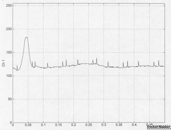
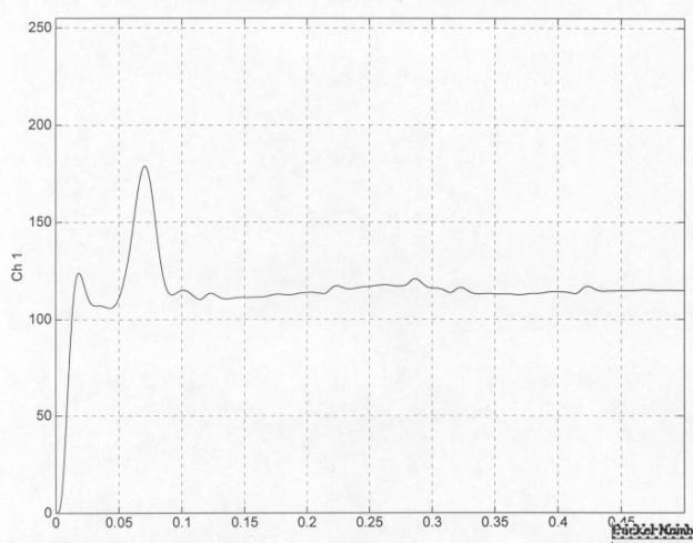
they are admitted into the hospital. In figure 6, we can see a premature
ventricular contraction (PVC) captured from a patient with the VitalCam. After running for several minutes, a patient
with a history of PVC experienced a premature ventricular contraction, which is
seen in the abnormal P wave, upward deflection, pointed with the arrow in
figure 6. Before running, this
patient’s ECG was taken as seen in figure 7 exhibiting typical upward
deflection reflecting the P wave resulting from the alternate contractions of
the atria. More visible in figure 6 are the Q, R, S, and T waves that result
from the actions of the ventricle. With
the VitalCam and a wireless network, hospitals can make telemetry information
available to physicians and nurses constantly attached to patients. The
VitalCam is also capable of performing an EMG as seen in figure 8 below. The
blocky appearance of the EMG is a consequence of how the 8 bit Analog to
Digital converter produces samples from the analog signal. Made of off-the-shelf components, the
VitalCam is inexpensive. At home,
patients can take their own ECG or EMG as seen in figures 6, 7, and 8. (See
Appendix for additional screenshots of captured data through BioSignals) Thus, it lends itself
The
VitalCam has many medical applications.
Due to its small size, patients in hospitals will have greater
flexibility to move around the hospital while still being monitored by medical
staff. In particular, patients with
cardiovascular episodes who come through the emergency room currently are often
attached to one telemetry system in the emergency room and different one once
they are admitted into the hospital. In figure 6, we can see a premature
ventricular contraction (PVC) captured from a patient with the VitalCam. After running for several minutes, a patient
with a history of PVC experienced a premature ventricular contraction, which is
seen in the abnormal P wave, upward deflection, pointed with the arrow in
figure 6. Before running, this
patient’s ECG was taken as seen in figure 7 exhibiting typical upward
deflection reflecting the P wave resulting from the alternate contractions of
the atria. More visible in figure 6 are the Q, R, S, and T waves that result
from the actions of the ventricle. With
the VitalCam and a wireless network, hospitals can make telemetry information
available to physicians and nurses constantly attached to patients. The
VitalCam is also capable of performing an EMG as seen in figure 8 below. The
blocky appearance of the EMG is a consequence of how the 8 bit Analog to
Digital converter produces samples from the analog signal. Made of off-the-shelf components, the
VitalCam is inexpensive. At home,
patients can take their own ECG or EMG as seen in figures 6, 7, and 8. (See
Appendix for additional screenshots of captured data through BioSignals) Thus, it lends itself  to
applications where patients can take the VitalCam home and have it transmit
data over the Internet to physicians.
to
applications where patients can take the VitalCam home and have it transmit
data over the Internet to physicians.
 During
the development of the VitalCam, many changes had to be made to its original
design. Initially, the VitalCam was
designed to use the TCP/IP Internet transmission protocol by having the Atmel
processor send data through Seiko’s I-chip.
The I-chip would handle the details of Internet protocol. After extensive work with the I-chip, it was
determined that with the I-chip, the maximum bandwidth that the VitalCam could
achieve was 4 kHz or 4,000 bytes/sec.
By switching to the UDP protocol, the bandwidth doubled at the cost of
reliability. This compromise was made
for the prototype. In future versions of the VitalCam, a TCP/IP stack would be
written for the Atmel so that the processor can manually handle all Internet
communication as it does presently with UDP.
During
the development of the VitalCam, many changes had to be made to its original
design. Initially, the VitalCam was
designed to use the TCP/IP Internet transmission protocol by having the Atmel
processor send data through Seiko’s I-chip.
The I-chip would handle the details of Internet protocol. After extensive work with the I-chip, it was
determined that with the I-chip, the maximum bandwidth that the VitalCam could
achieve was 4 kHz or 4,000 bytes/sec.
By switching to the UDP protocol, the bandwidth doubled at the cost of
reliability. This compromise was made
for the prototype. In future versions of the VitalCam, a TCP/IP stack would be
written for the Atmel so that the processor can manually handle all Internet
communication as it does presently with UDP.
With its vast applications, the VitalCam is an affordable and unique solution for providing telemetry information. The use of wireless Ethernet and Internet along with its higher sampling rate makes an attractive solution for the previously described applications.
Glossary
802.11b – Wireless Ethernet standard employed by Cisco Aironet 340 series card.
A/D – Analog to Digital Converter; converts an analog signal into binary format.
ARP – Address Resolution Protocol
ARP request – Method to find a network device exists on the network. An Address Resolution
Protocol request is typically issued before data is transmitted to a destination computer.
Atmel – Company producing the ATMEGA 103/L processor employed in device
BioSignals – Software application that reads data from either VitalCam or BioRadio and display
waveforms and performs signal analysis for researcher.
Buffer – Memory used to store data temporarily.
Checksum – A computed value based on the contents of the UDP packet that is used to detect the
corruption of data
DOS – Disk Operating System
EEG – Electroencephalogram
ECG – Electrocardiogram (EKG)
EKG – Electrocardiogram (ECG)
EMG – Electromyogram
I-chip – Internet chip made by Seiko that can handle the TCP/IP and UDP Internet protocols,
relieving the Atmel processor the work of network handshaking.
IP – Internet Protocol
IP header – Internet Protocol code that appears on a TCP/IP or UDP packet
kHz – 103 samples/sec
Local Wireless Network – Wireless 802.llb network that is linked via Wireless Ethernet cards
MBps – Megabits per second, 106 bits/sec
MAC address – The hardware address for a network device connected to a shared network.
(Media Access Control)
Matlab – Mathematics application, which BioSignals requires to run.
PCMCIA – Personal Computer Memory Card International Association
PVC – Premature Ventricular Contraction
P Wave – First upward deflection observed in an EKG that refers to the alternate contraction of
the atria.
Q, R, S, and T Wave – Deflections that result from the action of the ventricles seen in an EKG.
Radiosonde – A device that measures meteorological data.
TCP – Transmission Control Protocol
TCP/IP – Transmission Control Protocol/Internet Protocol
Transducer – A portion of a telemetry device that obtains
readings.
Transmission Module – A portion of a telemetry device that transmits data.
UDP – User Datagram protocol
VitalCam – Wireless medical telemetry device created in this research project to take readings
from a patient and transmit it over the Internet to a researcher at computer.
Wireless Ethernet – Ethernet
cards that employ the 802.llb standard.
Appendix
Note that a compact disk containing the files for BioSignals and the applications mentioned in the thesis has been attached to this thesis.
Screenshots of
BioSignals
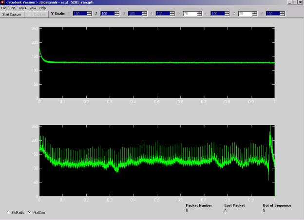
In the following screenshots, the relevant data is shown in the bottom window is of active channel, which was attached to a subject. The first window displays data from the other channel that does not have leads attached to it.

The above screenshots shows the result of BioSignals opening a saved data file of a patient’s ECG while sitting.
The above screenshots shows the result of BioSignals opening a saved data file of a patient’s ECG after a brief run.
The following is an electroencephalogram of me sitting down captured via the BioSignals application.
The following is my electroencephalogram captured with BioSignals after applying a high pass 44 Hz filter.
Screenshot for VitalCam Simulator (UDPc.exe)

BioSignals Help Section
BioSignals Help
Version 2.0
Last Updated May 3, 2000
Introduction
Welcome to BioSignals
version 2.0. The following help menu is
intended for users who are
familiar with the operation
of the BioRadio. This application is
intended to run on Matlab version 5.3.
Your copy of Matlab must
have the data acquisition and signal processing toolboxes installed.
The following help Menu is
broken down in the following manner:
·
Main Screen
·
File Menu
·
Tool Menu
·
View Menu
·
Help Menu
·
Notes
·
New for version 2.0
·
Questions and Comments
Main Screen
After typing biosignal at
the Matlab prompt, you should see the following screen:
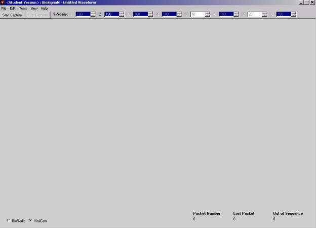
On the toolbar, there is a Start
Capture and Stop Capture button. If the
BioRadio is on and transmitting data, the start capture button will display in
the incoming data as waveforms, and it will store data for each channel into a
temporary file. If you wish to save
your data, go to the save command under the file menu. The stop capture button will enable you to
stop capturing data. After clicking the start capture button, you cannot modify
any of filters or signal processing elements or viewable channels that you
applied to the incoming
data. To the right of the stop capture
button are the Y-scale options for the channels that will be viewed when
capturing begins. The following diagram illustrates the Y-scale option bar.
![]()
If a channel is not
activated on the BioRadio or not viewable, the corresponding y-scale options
will be dimmed. To change the y-scale
for a particular channel, click the up and down arrows for each y-scale. Once
you have chosen the y-scale that you want, you must click onto the
number, ensuring that the number is in blue and has a light grey square
surrounding it as seen below for
channel 1:
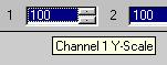
If you do not click on the
number after selecting it, the y-scale you chose will not be applied to that
channel. The y-scale value is the only
setting which can be modified during capture.
File Menu
Open
The following is the open
menu:

Select a previously saved
data file with .grh extension, and click open. BioSignals will graph each saved
channel on the main window.
Save
After clicking save from
the file menu, you will be prompted to type in a filename.

Type in a filename like
"Professor Land's Data" or "Professor Hoy's Data.grh" in
the file name text box. Click Save. The files will be saved as Professor Land's
Data.grh or Professor Hoy's Data.grh,
respectively.
Export to Audio File
After clicking export to
audio file from the file menu, you will be prompted to type in a filename.
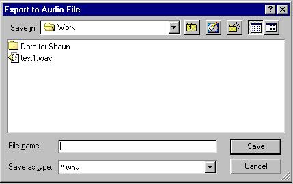
Type in a filename like
"Professor Land's Data" or "Professor Hoy's Data.wav" in
the file name text box. Click Save. For
each channel that data was being acquired from the BioRadio, BioSignals will
save a wav file with the above filename and a number appended to the end of the
filename. For instance, if channels 3 and 4 were acquired, BioSignals will save
Professor Land's Data3.wav and Professor Land's Data4.wav to the prescribed
file location.
Setup
After clicking the Setup,
the following menu appears:
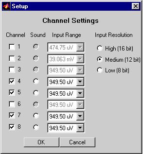
With the exception of the
sound option, all settings that you set here are physical settings that you
manually set the BioRadio with using the BioRadio Configuration WizardÓ. Before capturing data, you should activate
all channels that were set with Wizard and ensure that all the input
ranges and input resolutions are correct.
Select the channel you want to hear sound from. If you do not want to
hear sound, click the sound
radio button that is already selected.
You should notice that the sound radio button no longer has a dot in it,
indicating no sound will be played for that channel. Note, if none of the activated channels has sound button
activated, no sound will play. Click ok to save changes, or click cancel to
erase changes.
(Note only one channel
can have sound at a time.)
Print
In version 1.0 of
BioSignals, the print function is not yet implemented.
Exit
Press exit to quit
BioSignals application. If the x button
at the top right of the program is used to close the BioSignals, the
communications port will not be closed, and all files that are open will not be
closed properly. Please be sure to
press exit from the file menu to quit BioSignals.
Tools Menu
Timer
This function is to be
implemented in the next release of BioSignals.
Signal Processing
The following the menu that opens when you click the Signal Processing option
or
hit CTRL+S.
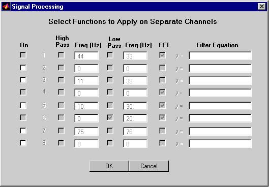
To enable Signal Processing
for a particular channel that is activated and is set to be viewable, click the
on checkbox for that channel. Once you
click the On box for a particular channel, in this case channel 2, the menu
will change to enable all the menu items corresponding to that channel as seen
below.
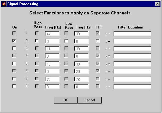
When you click High Pass or
Low Pass, the frequency box to the left of those respective
checkboxes will be
enabled. Enter in a cutoff frequency
(in Hertz) to the frequency box. In
this version of BioSignals, if you enter a character into the corresponding
freqency box, the ascii value for that
letter will be used for
either the High or Low Pass cut off frequency.
Click the FFT
checkbox to enable FFT to
be applied to the signal. Press OK to exit and save changes, or press
Cancel to exit and not save
changes. (Note: Filter Equation is not implemented
in version 1.0 or 1.1a
of BioSignals)
View Menu
Channels
Press Channels from the
View menu or press CTRL + N to bring up the following menu:
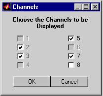
The channels that you will
be able to choose from to view while capturing data from the
BioRadio will be those that you activated using the BioRadio Configuration WizardÓ and
set in the previously described Setup menu. The channels that you select in this menu will be
viewed in the main window after pressing the start capture button in the toolbar of this program.
(Do not modify these settings while capturing is in progress!)
Help Menu
Contents
Press the Contents Menu
from the help to obtain this help screen.
You must have
wordpad installed in your windows
based machine to obtain this help screen.
Online Support
Press Online Support to
obtain web page help with the use of this program. To use
this feature you must have
a web browser installed on your system.
About BioSignals
This screen allows the user
to determine what version of BioSignals is being run.
Notes
If the BioRadio is not on
and connected to the machine running BioSignals, the BioSignals program
will not function
properly. This means do not press
Start Capture if the BioRadio is not on.
This version of BioSignals
has minimal error checking, so be sure to enter proper values
for high or low pass
filters. If you do a band pass filter (high and low pass filters are both
enabled), then the high pass cut off should be lower than the
low pass cut off.
Otherwise, BioSignals may
behave erratically.
Finally, please be sure to
shut down BioSignals by going to clicking CTRL+Q or by clicking
exit from the File
Menu. If you click x at the top right
of the screen, the communication ports
on your computer will not
be closed properly.
New for version 1.1a
Two features are new for
version for 1.1a, print and copy commands.
The print command is
located in the file menu.
The print command will print any graphs displayed in the BioSignals
main window. The copy command is located in the new edit
menu as seen below:
 .
.
Press Ctrl + C as a
shortcut to copy all the graphs which is exportable to any standard windows
application.
New for version 2.0
Support for VitalCam has
been included. Timer Menu has been
eliminated from the tools menu. In addition the Signal Processing menu no
longer has an equation input field for each channel. When configured for the VitalCam, BioSignals will transmit a
packet to the VitalCam reconfiguring it.
Questions and
Comments
Send Email to
Shaun Chandran or Benjamin Greenblatt
shaun@chandran.cc or
bmg4@cornell.edu
Ó BioSignals by
Shaun Chandran and Benjamin Greenblatt.
References
Gardner, Elizabeth. “New Device Gives Mobility to Monitoring Equipment.” Modern
Healthcare 10 June 1991, Lexis-Nexis. Online. Lexis-Nexis. 5 February 2001.
Stringer M.D., Roger. Personal interview. 6 February 2001.
“Telemetry.” Encyclopaedia Britannica (5 February 2001): n. pag. Online. Internet. 5
February 2001.