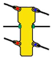
 Top View |
 |
BUG
The Hexapod Walker
by Nidhi Kalra
May 2001
II. Design
My primary goal in designing Bug is that it should be useful in two ways: easily replicable and easily extensible. First, I wanted to stay away from expensive parts, fancy software, specific tools, or obscure circuit components which would slow development and cause much frustration all around. A simple design leads to the second goal: extensibility. I don't want to have to design and build a new bug every time I'd like to add a cool feature. These guidelines hold true for all parts of Bug: the body, software, and circuitry.
A. Mechanical Design
By definition, a hexapod walker has six legs. While it would have been nice to have six servos, in order to minimize cost, I paired up the legs and used only 3 servos.
|
Top View |
|
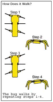
How does it walk?
This diagram is ripped off the Lynxmotion catalog, but my bug works the
same way, except that mine starts with step 2 and then continues the pattern.
1. (Step 2) It tilts itself so that one pair of side legs are off the ground and the other pair is on the ground. It does this by using the center servo to pull one center leg under and push the other one out. So, for example, if the center right leg is pulled down, the right pair will be off the ground and the left pair will be on the ground.
2. (Step 3) Then, the legs that are on the ground push backwards, moving the bug forward, while the pair in the air move forward to prepare for the next step. Continuing the example, the left pair push backwards and propel the bug forward while the right pair move into position.
3. (Step 4) The center servo tilts the bug the other way which results in the opposite effect of Step 2. In this case, the right pair would be on the ground and the left legs not.
4. (Step 1) And, finally, the pair on the ground again pushes back and moves the bug forward. So, the right legs push back and propel the bug, while the left legs prepare for step 3.
Repeating this sequence makes it walk.
 |
How does it turn? Consider the walking sequence (steps 1-4 above) a standard cycle. The bug turns by changing the phase of one of pair of legs by a half a cycle. I've shown this in the diagram at left quite literally (I swapped the right sides of Steps 1 and 3). Consider a lead side the side that pushes the bug forward and moves "normally." While the lead side moves normally (say from step 2 to 3), the other side moves abnormally by being out of phase half a cycle (from step 1 to 2). If the left side is the lead side, the bug turns right. If the right side is the lead side, the bug turns left. This is actually not a very hard thing to figure out, even though its not a very obvious algorithm. It just happens to require a working bug to truly visualize this working at all. |
Besides walking, the bug also knows when its run into something. A small switch with to antennae triggers whenever it runs into anything and sends a signal to the chip. The only "concern" here is that the bug runs into the obstacle at an angle that presses down the switch.
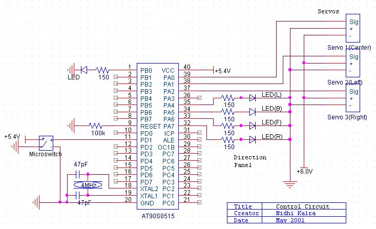
B. Electrical Design
There are two main electrical components to Bug: driving the servos and the chip circuit itself.
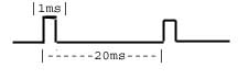 |
The servos are very simple: they are driven by pulses. The time between pulses is a standard 20 ms. A 1ms pulse results in a 0 degrees position, 2 ms results in 180 degrees, and 1.5ms in 90 degrees. I have the center servo moving 180 degrees to push and pull the center legs, and the side servos moving 90 degrees to get the maximum reach on the legs while staying the physical confines of the bug..
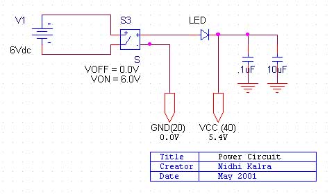
The electrical design is also fairly simple and consists of three major components. First, there is the power circuit, which provides the chip with 5.4V and the servos with 6 V. A servo pack/4 AA batteries work just fine for this since an LED will knock off .6V, and 5.4V is good enough for the chip. What's interesting is that although the servos are running on 6 volts, the signal they receive is only 5V. As it turns out, they still run just fine.
The second portion consists of the control circuit for the bug. I control the servos with three separate headers consisting of power, ground, and signal; this is pretty straightforward. Then there is the panel of LED's which is also really simple: LED's + resistor and you're set. There's the LED on PB0 which is a test LED for whatever you need. This comes highly recommended because its the easiest way of knowing if something is working (i.e., interrupts, functions, *the chip itself*). The microswitch I wired directly to PD2, the pin for external interrupts. And that's the situation with the control circuit.
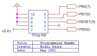
Finally, the programming header is a must if time is at all important to you. There is a schematic of this in the STK200 documentation, but these aren't the same. I was using that as a guide except, being a CS major, didn't know what was up with the diodes. So I left them off and it works. Other people have tried the STK 200 schematic for the programming header as well, and it doesn't work for them either. Mine does. No, really.
C. Software Design
Once the bug was built and the circuit was finished, I could actually make this thing walk with a good control program. I went through several different stages before I found a method of control that I liked. The first job was simple: control a servo. The best way to do this, I found, is to use two timer interrupts, one every 20ms and the other every .5ms. The position is a result of the length of the pulse, which is controlled by some variable x, 1<= x <=4. The first interrupt started the cycle by outputting a high signal as shown in the diagram above. Once the pulse starts, the second interrupt counts x down by 1 every .5 ms, thus regulating the pulse length. So, lets say we want it at 180 degrees which corresponds to a 2ms pulse; that is, 4 x .5ms interrupts. So, the first interrupt starts the pulse, the second counts down to 0 and sets the pin low when it reaches zero, and the cycle continues. Each servo has its own variable x, and the right pattern of delays and x values will make the bug move.
With this down, the next question is, how do you make a sequence of these steps? My first idea was to use an array of values that consist of (servo, position) pairs. This worked for walking forward very well. The program looped through the array, setting servo values and delaying when necessary. This works fine for a static movement, which was my first goal. However, I found this too specific for my goal of dynamically changing direction. I couldn't have four arrays of variable length and try to swap the contents of them. So, instead I used a function approach: there is a function for each direction and it has about ten instructions each that have the servo settings for each direction. The only thing the main program does is check which function to call and how long to let it loop (i.e., how many steps to turn or walk). This worked really well for the object avoidance. The external interrupt created by the microswitch alerts the bug that its run into something, at which point it sets a variable that lets the main program know to switch directions.
Once this was working, I thought it would be nice to have it do something intelligent. I've programmed the bug to know when it is in a corner and then to get out of it. If it runs into something it first tries going left. If it runs into something there it tries the right side. If it runs into something there, too, it decides its at a dead end and backs up and leaves the way it came. If, while its going through this sequence, it manages to go 24 paces in any single direction, it decides its not in a corner anymore and restarts the sequence. So, its a smart bug. Hopefully it will now figure out when its in a corner before it runs into the walls.
That's the gist of how I did it. The appendix make the specifics pretty clear; everything is commented either on this page or in there. For a mechanical how-to, check the pictures. When I perfect my bug mechanically, I'll put up step by step directions on how to make your own.