You will build a system that will vary the speed of a race car based on its location on the track using hall-effect sensors and display the lapcount and running time of the car on an LCD display.
Procedure:
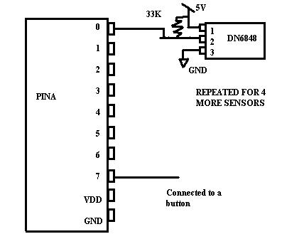
The DN6848 is a Hall Effect sensor that is sensitive to a directional magnetic field. It only detects a strong magnetic field and outputs a logical value making it ideal for this lab. Since it can only detect a strong field, we don't have to worry about a car on the neighboring track that could trigger the sensor and the logical output makes the sensor compatible with the Mega32. For this lab, you will be given 4 sensors which you will be allowed to place anywhere underneath the track. It is suggested that one sensor be placed near the "Start/Stop" line on the track since you will need to stop the car at that line after 5 laps. You will be given a fifth sensor which will be placed at a designated spot on the track that is within a track length of the finish line. This sensor must be used to turn off the timer. Your car must stop between this sensor and the finish line such that it will shut off the timer, but not cross the finish line. This means the car must be within 5-10 cm of the finish line. Note that the sensor will produce a logical "0" when it detects a magnetic field and a logical "1" otherwise. Also note that you will need to place the sensor up against the metal underneath the track since it will detect the magnetic field directly from the magnets with in the car and not from the magnetic field produced by the motor. These sensors are directional so make sure to place the sensor facing the correct direction. Here is a basic code and schematic that will allow you to experiment with the sensors and see how they work.
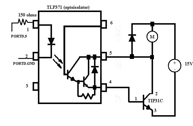
The actual control of the race car will be done through PWM (pulse width modulation) and opto-isolation. An example code of PWM is listed here which will operate the race car at one speed as soon as the chip is turned on and everything is hooked correctly. Note that the actual output from the PWM (PORTD.5) is a weak signal will not be able to drive a race car alone. The race car set needs 15V to operate. One of the tracks will be set to 15V and the other track will be be controlled by the output from the PWM. The circuit shown here will take the output from the PWM and use it to control the gate of a TIP31C (NPN bipolar transistor) which when turned on will pull the other track down towards ground. The control of the gate is done through opto-isolation using the TLP371 so that we have two separate circuits in this design (as explained in lecture). This will control the average current running through the motor. The faster the PWM, the more the higher the average current in the motor and vice versa. This is good because DC motors operate on the principle of induced magnetic field. The amount of current within the motor induces a magnetic field which the strength of controls how fast the motor turns.
Finally to add the finishing touches to the lab, you will implement a lapcounter and a timer using techniques developed in previous labs. The timer should be the only part of the code that uses interrupts to function.
Your race car should be able to beat the staff car which doesn't use sensors and operates at a constant high speed.
Assignment
Write a program and construct a circuit which will
You will demo all the features above to your TA.
Your written lab report should include: