Hardware Design
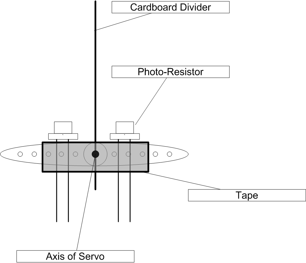
The hardware design for the light tracker is fairly simple. Below is a top-down
view of the arm and the light sensors attached to the axis of the servo motor.
Light Sensor Details

Figure 1: Top-down view of the light tracker assembly.
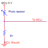
The light sensors used in this tracker were photo-resistors, which are simply devices that change resistance depending on the intensity of light incident on them. Photo-resistors have a very high resistance in complete darkness and low resistance under bright light. Photo-resistors are very simple to use because one can just use a voltage divider circuit to calculate its resistance to determine the intensity of light it sees.
The leads from the photo resistor was connected to the voltage divider circuit shown in Figure 1 using banana clips with one of the leads going to Vcc and the other to the node just above the 10K resistor. The entire assembly was held together with tape and wire wrapped around the oval shaped arm attached to the servo motor. The piece of cardboard that separates the two photo resistors is approximately two centimeters wide and 4 centimeters long. The cardboard was designed to cast a shadow on one of the photo sensors so that the only way that both photo-resistors have the same resistance is when the piece of cardboard points in the direction of the light source, thus eliminating the shadow.

Figure 2: Photo-resistor circuit
The MCU will measure the voltage dropped across the 10 k ohm resistor, which will vary from approximately zero volts, when the photo-resistor is in complete darkness, to close to five volts, when the photo-resistor is exposed to very bright light. The 10K resistor was chosen because the minimum resistance of the photo resistor was measured to be around .3 k ohms under bright light and the maximum resistance in complete darkness was greater than 100K. Thus I needed a resistor that was sufficiently greater than .3K ohms and sufficiently less than 100K ohms or else the range of voltages at the MCU input pin would be limited. For example, if I chose to use a .3K ohm resistor, under bright light the maximum voltage at the MCU would only be 2.5 volts. Likewise, if I used a 100 K ohm resistor, the minimum voltage at the MCU would be 2.5 volts. Therefore I chose a 10k, which is ~10 times greater than the minimum resistance of the photo-resistor and ~10 times less than the maximum resistance of the photo-resistor. This choice allowed a voltage swing of between 4.85 volts in the light to less than .45 volts in the dark. Since I used a 5 V power rail, I connected the AREF jumper on the STK 500 and configured the ADC use the external AREF (5V) as the voltage reference.
Servo Motor Details.
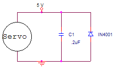
The servo motor used in this tracker has three colored leads, one for Vcc(Red), one for ground(Brown/Black), and one for control (Orange). Below is the circuit for the Vcc and the ground connections for the servo. Since the servo used in this tracker is a standard RC servo, it is controlled by a variable duty 5 V pulse with a period of approximately 20ms. The range of the servo is 180 degrees with a .5 ms pulse representing 0 degrees and a 2.5 ms pulse representing 180 degrees. The servo used in this lab had a fairly high torque and could drag the wires connected to the light sensors without any difficulty.

Figure 3: Protection circuit for the power rails
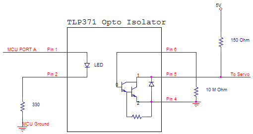
Like any motor, the servo has a large inductive spike whenever it turns on or off, so the capacitor and inductor are there to prevent any corruption of the power rail due to these spikes. Note that the servo’s 5V and ground rail are from a separate power supply and not connected to the MCU’s 5V and ground lines. To protect the MCU’s PWM output line from the noisy motor, I built the following protection circuit based around a TLP371 opto-isolator.

Figure 4: Protection circuit for the servo control line.
The PWM signal from the MCU goes into Pin 1 of the TLP371 and the output to the servo control line is connected to Pin 5. The 10 M ohm resistor placed between pins 4 and 6 was to reduce the turn off time of the opto-isolator to around 80 μs from around 90 μs without the resistor; unfortunately this resistor increases the turn on time by about 2 μs.