High Level Design
Rationale
The idea of a light tracker came from Professor Land as an idea for a possible
ECE 476 motor control lab. The ECE 476 course already had a temperature
controller lab that involved basic motor control, but the controller in that lab
simply turned a DC fan on and off in response to tine input from a temperature
sensor. The proposed light tracker lab would require more precise control over
the motor and the input from the sensors would be used to directly calculate the
motor’s degree of response. The photo-resistors that were used in the light
tracker were chosen because they were simple to use and could be used with a
simple voltage divider circuit and the ADC’s on the Mega32. Also, the servo
motor was chosen because of its generic nature and because it could be
controlled through the microcontroller’s PWM.
Background Math
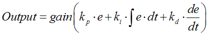
The PID algorithm is based on the following equation:
The term ‘e’ is a function represents the error in the
system, or in context of the light tracker problem, the difference between the
outputs of the light sensors. The output is a weighted sum of the error, the
integral of the derivative function, and the derivative of the error multiplied
by a ‘gain’ value. The output is a signal sent into the system that ideally
should minimize the error as time progresses. Thus the output is used to
correct the position of the servo to ideally obtain a zero error. The three
terms in the above equation are known as the Proportional, Integral, and
Derivative terms respectively. Using just the proportional term to drive the
output tends to make the system overshoot as its trying to minimize the error.
In terms of the light tracker, it will make the servo oscillate back and forth
as it tries to find a position that will make the inputs to both of the photo
sensors equal. Adding the derivative term will make the system settle faster
since its value depends on the slope of the error. Thus if the error is either
increasing or decreasing rapidly, the derivative term will be a large component
of the output to drive the system in the direction of zero error. Thus the
derivative term will make the system more stable by applying larger correction
if there is a rapid change in the error. The purpose of the integral term is to
reduce the sum of squared errors in the system. If the error becomes small and
constant, the proportional term and derivative term will also be small; however,
the integral term is essentially a running average, so it eventually accumulates
all of the small errors and apply the appropriate correction to the output. As
a result, the integral term will increase the settling time as it slowly moves
the system toward zero error. Intuitively, the proportional and derivative term
will make the light tracker quickly move toward the light source, and the
integral term will handle the small corrections so that the light tracker will
point exactly at the point where the light sensors report that same output.
Lastly, the ‘gain’ value is the overall gain of the PID control, technically, it
can be combined with the
![]() and
and
![]() term weights.
Initially set all of the weights to a low value and increment them until the
desired operation is reached. If the tracker is constantly overshooting,
turn down the 'gain' term and raise the
term weights.
Initially set all of the weights to a low value and increment them until the
desired operation is reached. If the tracker is constantly overshooting,
turn down the 'gain' term and raise the
![]() term.
term.
Logical Structure
The control program for the light tracker polled the Port A input pins for the light sensor output and controlled the servo motor with a PWM output from Port D. The program is divided into four principle components: the kernel, the sensor handler, the servo controller, and the button handler. These components are detailed below
Since the light tracker does not broadcast anything and is not intended as a commercial product, it does not meet with or comply to any IEEE, ISO, ANSI, DIN, or any other standard.
Existing Patents
There are multiple existing patents that are relevant to the servo based light tracker. US patent number 6,947,073 defines an apparatus and a method for tracking moving targets. This patent is quite general and could be extended to a light tracker that follows a moving light, much like the tracker described in this document. US patent number 6,926,673 discusses a method to track the position of an ultrasonic beam. Although this patent does not mention any kind of moving apparatus, it does track energy, in this case sound, emitted by an object much like a light tracker.