You will build a servo based light tracker which will turn to and follow the brightest light source that it "sees" using a PID algorithm to ensure fast and smooth operation of the servo. The PID control should allow the light tracker to quickly turn to a bright light source without any overshooting or oscillations.
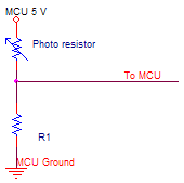
The light sensors used in this lab are photo-resistors in can-type packages. Photo-resistors change their resistance depending on the amount of incident light with typical values being ~.3K ohms under bright light to ~100 K ohms in darkness. You will need to construct a voltage divider circuit and use the ADC to read the voltage to determine the light intensity seen by the photo-resistor. An example circuit is shown below, you need to choose a value for R1 that will give you a wide range of voltages at the MCU input pin. You should use the 5V external AREF for the ADC conversions.

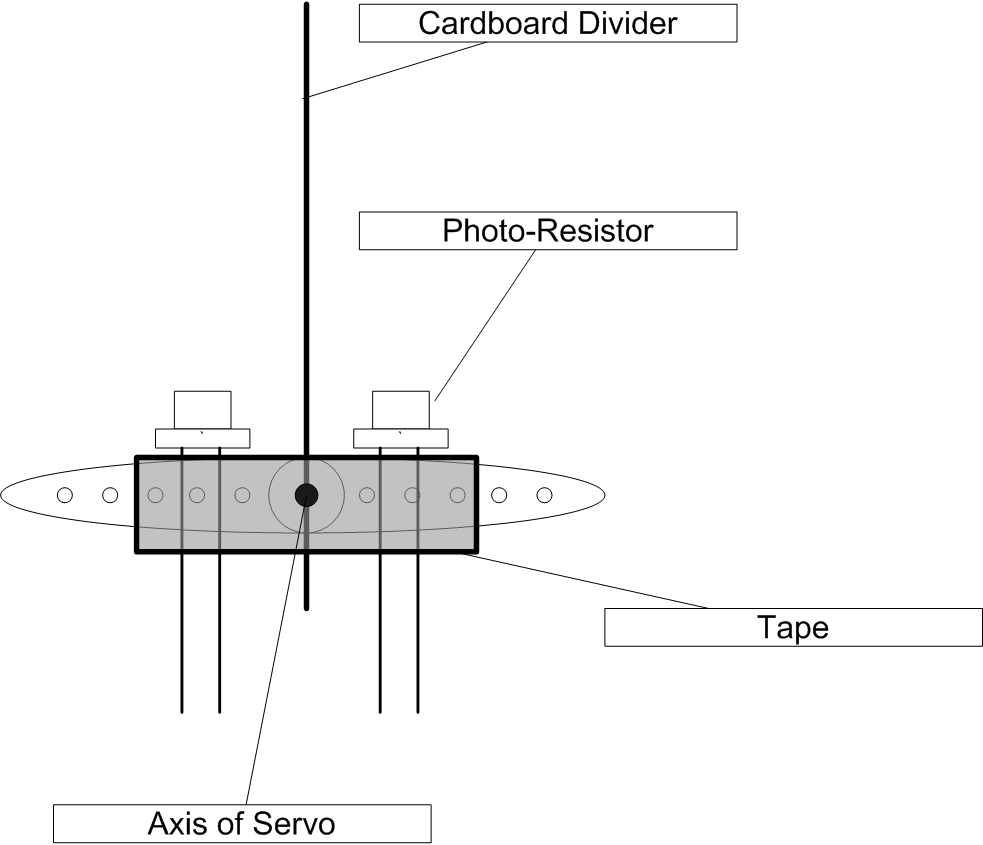
The photo-resistors should be mounted on top of the servo along with a suitable divider between the two light sensors according to the diagram shown below. The leads of the photo-resistors should be connected to the above voltage divider circuit using banana clips or other suitable means.

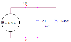
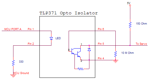
Additionally, you will need to control the servo using a PWM output from the MCU. The servo motor expects a 5V pulse ever 20ms with a pulse width of between .5 and 2.5 ms. The width of the pulse determines the servo's angular position with .5 ms representing 0 degrees adn 2.5 ms representing 180 degrees. Servo motors create inductive spikes when they are turned on or off, so a protection circuit for the MCU control line and the power rail is necessary. The first circuit shown below will reduce the inductive spikes on the power rail and make sure that the signals coming from the second opto-isolator circuit are clean. The pinouts of the TLP371 are shown in the circuit diagram. Note that the servo must be connected to a separate VCC and GROUND from the MCU.


PID Control

The term ‘e’ is a function represents the error in the
system, or in context of the light tracker problem, the difference between the
outputs of the light sensors. The output is a weighted sum of the error, the
integral of the derivative function, and the derivative of the error multiplied
by a ‘gain’ value. The output is a signal sent into the system that ideally
should minimize the error as time progresses. Thus the output is used to
correct the position of the servo to ideally obtain a zero error. The three
terms in the above equation are known as the Proportional, Integral, and
Derivative terms respectively. Using just the proportional term to drive the
output tends to make the system overshoot as its trying to minimize the error.
In terms of the light tracker, it will make the servo oscillate back and forth
as it tries to find a position that will make the inputs to both of the photo
sensors equal. Adding the derivative term will make the system settle faster
since its value depends on the slope of the error. Thus if the error is either
increasing or decreasing rapidly, the derivative term will be a large component
of the output to drive the system in the direction of zero error. Thus the
derivative term will make the system more stable by applying larger correction
if there is a rapid change in the error. The purpose of the integral term is to
reduce the sum of squared errors in the system. If the error becomes small and
constant, the proportional term and derivative term will also be small; however,
the integral term is essentially a running average, so it eventually accumulates
all of the small errors and apply the appropriate correction to the output. As
a result, the integral term will increase the settling time as it slowly moves
the system toward zero error. Intuitively, the proportional and derivative term
will make the light tracker quickly move toward the light source, and the
integral term will handle the small corrections so that the light tracker will
point exactly at the point where the light sensors report that same output.
Lastly, the ‘gain’ value is the overall gain of the PID control, technically, it
can be combined with the
![]() and
and
![]() term weights.
Initially set all of the weights to a low value and increment them until the
desired operation is reached. If the tracker is constantly overshooting,
turn down the 'gain' term and raise the
term weights.
Initially set all of the weights to a low value and increment them until the
desired operation is reached. If the tracker is constantly overshooting,
turn down the 'gain' term and raise the
![]() term.
term.
Assignment
Write a program and construct a circuit which will
You will demo all the features above to your TA.
Your written lab report should include: