WIRELESS TRANSMIT AND RECEIVE
txrx.c
Introduction
txrx.c is the wireless transmit and receive driver designed for the Atmel MEGA32 for use with the Radiotronix RCT-433-AS transmitter and the Radiotronix RCR-433-RP receiver. The microcontroller interfaces to the transmitter and the receiver through the serial TX/RX pins. This driver is designed to abstract away the mechanism by with a packet is transmitted by allowing the user to transmit at packet granularity without having to account for the physical layer.
Concept/Theory
OSI Model
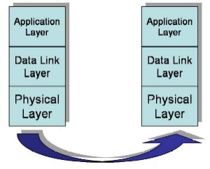
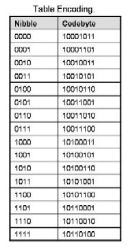
The lowest layer is the physical layer which is composed of the transmitter and receiver operating at 433MHz using On-Off keying. A transmit 1 is achieved by a signal, and a transmit 0 is no signal. (Note that because of this, the data sent must be DC balanced). The next level is the Data Link layer, which is responsible for encoding and decoding the data. As an encoding scheme, a byte is split into two nibbles. The encode method encodes each nibble separately into DC-balance bytes. There are 70 DC balanced bytes, and of those the ones that start with a 10 were selected. Of these, 10101010 is reserved for synch. This leaves 19 byes that can be used to map the Binary-4 space. The three that were removed had the most number of ones and zeros together (which would upset the DC balancing). The below table presents the character set used. Above the data-link layer is the application layer which is responsible, here, for the direct interpretation of packets.
Intended Hardware
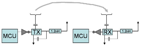
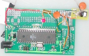
The intended hardware for this driver is the Radiotronix RCT-433-AS transmitter and the Radiotronix RCR-433-RP receiver chips interfaced to the MCU through Port D.0 and D.1, the USART TX and RX ports. The intended circuit diagrams on the connections of these chips are provided in the diagram below. Additionally, the picture shows an example of a transmitter circuit.
Packet Encodings/Variable Length
The encoding and decoding both occur through a table look up because an exhausting search for a pattern revealed nothing. Note that there is a built in 1-bit error detection code by virtue of the DC balancing. That is, that the hamming distance between pair wise bytes is a minimum of 2. (since for any 1 that becomes a 0, another 0 must become a 1). In addition to the encodings in the table above, there are two more dedicated characters, the packet start character and the packet end character. The start character is 202 and the end character is 212.
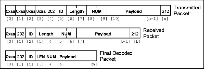
The packets can be of variable length. In the finally transmitted packet, the first four bytes are the synch character 0xaa. Next is the start character, followed by the transmitter ID. Next, two bytes provide for an 8-bit length, and 2 more bytes follow for the 8-bit packet number. Finally, the payload and the packet end character follow. The RXC ISR receives the packet without the first three synch characters. The finally decoded packet removes the DC balancing and recovers the original data, as demonstrated in the below diagram.
Usage Model
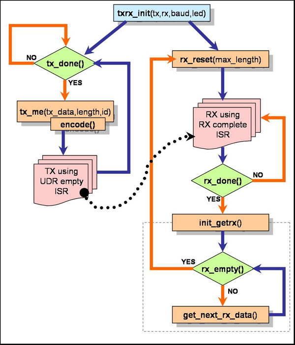
Consider the below diagram which depicts the usability of the driver functions. Notice the two flows, the transmit and receive sides. In general, it is recommended that only one side be used at a time. The provided init function can be called again and again to change the settings if it becomes necessary to oscillate between using one side or the other. The reason is to avoid cross interference when operating both wireless devices.
The gray box in the above diagram represents the iterator on the receive side used to iterate through the received bytes vector. The function specifications below will clarify how the usage model above works.
Function Specifications
General Functions
void txrx_init(int tx, int rx, int baud_num, char led)
This function sets the UCSRB and UBRRL register appropriatly. tx and rx should be either 0 and 1, depending on whether the functionality is desired. baud_num is the value that would be assigned to UBRRL. If led is 1, then the default LED on the protoboard is used to indicated activity.
char decodeOne(char msbyte)
This function returns the decoded character of the input.
char decode(char msbyte, char lsbyte)
This function returns the decoded character formed from the two input bytes.
Receive Side Functions
interrupt [14] void RX_complete(void)
This is the RXC interrupt service routine. It takes the received byte and places it in a receive buffer, allowing the next byte to be received. The ISR check for the packet start character and does not store the synchronization bytes. It also checks for the length bytes and looks for a packet upto the appropriate length.
void rx_reset(char max_rx)
This function is used to reset the receiver to allow it to receive the next byte. This function must be called inorder to receive the next transmission after one has been received. The max_rx input tells the receiver what is the maximum length of packet to expect. The bui;t-in max is 32bytes, this merely provides a failsafe incase one is desired.
char rxdone(void)
This function, when called, return 1 or 0 depending on whether the current packet has been fully received.
void init_getrx(void)
This function initiates the iterator that will return the bytes received.
char get_next_rx_data(void)
This function returns the next byte of the received packet.
char rx_empty(void)
This function returns whether the iterator has reached the end of the packet or not.
Transmit Side Functions
interrupt [15] void udr_empty(void)
This is the UDRE interrupt service routine. When the current byte has been transmitted, and the UDR becomes empty, the ISR takes the next byte off of the transmit buffer and places it in the UDR for transmission. If all bytes have been transmitted, then the ISR zeros the tx_ing flag.
void encode(void)
This function encodes the given data vector into a zero-balanced packet for transmission.
void tx_me(char tx_data[], int length, int id)
This function accepts the given data, the length, and the transmit id and sets up the transmission. If a transmission is in progress, the function ignores the inputs.
char txdone(void)
This function returns whether the previous transmission is completed or not. This must be called before the next transmission is setup.
Usage Examples
How to set-up a transmission
In order to setup a transmission, one must first call the txrx_init function as follows: txrx_init(1, 0, 249, 0) This sets the UCSRB to transmit, the UDRIE to 1, UBRRL to 249 and makes it so that the LED will not be used. After this, one must use the follwing function
tx_me(tx_data[],length, id) which will setup the necessary variables and call the encode()function to setup the packet. The next packet cannot be sent until the txdone() function returns a one.
How to set-up a reception
In order to setup a reception, one must first call the txrx_init function as follows: txrx_init(0, 1, 249, 0) This sets the UCSRB to receive, the RXCIE to 1, UBRRL to 249 (should be the same as the transmitter) and makes it so that the LED will not be used. Note that the rx_reset method need not be called here since it is a subset of the init method. However, it must be called again after the first packet is received. Once the rxdone method reveals that the packet reception is complete, the iterator must be initiated to extract the packet byte-by-byte. The get_next_rx_data function is called until the packet buffer is empty. Again, before being able to receive the next packet, the rx_reset function must be called.
How to set-up a packet loss free network with transceivers
With two nodes that have tranceivers, one can set up a system of packet-loss free transmission. When one node transmits a packet, it can require a confirmation from the receive side that the packet has been received. If no confirmation arrives with a constan period of time, the packet is re-transmitted. This process is repeated until the transmitting node receives confirmation that the packet has been successfully received. With this scheme, one must worry about the No Progress situation. If no confirmation is received after a few iterations, then perhaps the transmitting node and signal a loss of communication with the receiving node. The functions provided in the driver can be used to set this up, but remember to not have both transmit and receive active at the same time.
How to set-up a possible medium access contention (MAC) layer
With multiple nodes that have tranceivers, one can set up a system with MAC layer, where each node who wants to transmit turns the receiver on first to check whether there is an active transmission. If not, then the node can begin transmitting. If there is an active transmission, the node must wait until the transmitting node is done before transmitting.
The Code
The driver is txrx.c.