
Introduction
Bruce Land developed CodeVision 1.24.6 Debugger for Atmel Mega32 microcontrollers, a debugger which allows a user to link with a target program on a MCU, determine the program's state, and make changes. The program includes commands to read/write I/O registers, data registers, memory, and to determine the locations of the Codevision data stack and hardware stack. This program required using a communication program, such as HyperTerminal, to connect to the MCU and manually enter the commands. A simplified interface was desired so that the program could be more easily used by the ECE 476 Microcontrollers course. This program is an attempt to provide such an interface. Additional features, such as reading compiler generated .map file and printing, were added to the program to make it easier for the user to make sense out of the state of the target program.
Requirements
Create a UI to connect with and make available all functionality available in
CodeVision 1.24.6 Debugger for Atmel Mega32 microcontrollers. The
debugger will still be run on the MCU.
Software Design
1) Information To Display
Data Registers - Value, Variable, Byte Location, Full Value of Variable, Type
I/O Registers - Value, Variable
MCU Info - Value of MCU Status Register, Location of Top of Data Stack,
Location of Top of Hardware Stack
Memory - Value, Variable, Byte Location, Full Value of Variable
where:
Value - Retrieved from MCU
Variable - Name of variable corresponding to the data location in the loaded map file (see below)
Byte Location - Location of the byte in the variable in the loaded map file. A variable that is only
one byte long will have a byte location of 1.
Full Value of Variable - If part of a variable, this is the entire value for the variable.
This combines all the values for the different bytes of the variable. A single byte variable will have the
same data for value and full value of variable.
Type - Type of data register (Global, Local, or State Info) as listed in datasheet.
2) Programming Language
Visual Basic .Net was selected as the programming language for this project. This
program will hopefully be used by future ECE 476 classes, which may require maintenance
or changes to the source code. Bruce Land is the instructor for the course and will
lead any of the efforts to make changes to this program. He indicated that Visual
Basic would more easily allow him to maintain the software. I have past experience
in Visual Basic, so I was not against using the language. The advantages of Visual
Basic are that it is a fairly easy language to learn and use to create a User Interface.
3) UI Design
The UI is a balance between displaying as much MCU data as possible while keeping the program
easy to use. The list view on the left-hand side of the screen enables the user to quickly
view different data storage types in the list view on the right-hand side. Scrollbars on the side
prevent having to display all the information on the screen at once. The buttons on the left provide
easy access to the functions relating to the MCU. The menu bar at top includes functions which
do not require communication with the MCU.
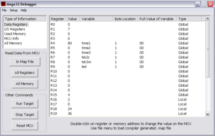
Program Screen Shot
4) Communicating With MCU
Visual Basic enables access to unmanaged functions that are stored in external files.
I declared reference to the communications procedures included in Kernel32.dll. These
functions enabled the program to set the serial connection properties, and read/write
to the port. The problem with these functions is that reading from a port required
knowing how many bytes would be sent. The functions are blocking and will wait until
enough bytes are received. Data received from the MCU is variable in size and that
size can not always be predicted. I had to enable timeouts to prevent needing to know
how many bytes will be received. Each stream of data received will read the bytes off the
port until it times out while waiting for the next byte. I adjusted the settings to reduce
the time out as much as possible while preventing slight delays in transmission times
from being interpreted as time outs. The status of the MCU (debug mode, running mode, or
power off) can change without any notification to the program. For that reason, the connection
is re-established each time the program communicates with the MCU.
After receiving the data from the MCU, I parse
out the data based on the expected data form of [i,r,or m] address value. The syntax for
sending and receiving data from the MCU was taken from Bruce Land's debugger documentation.
5) Reading MAP File
The CodeVisionAVR Compiler generates a .map file which indicates the locations of
all variables used by the target program. This locations are needed to debug the
target program. In the program I created, the user has the ability to load a map
file. Loading a map file allows the program to display the variable names for the
data registers and memory. It is slow to display and read the data values for memory,
so loading a map files enables the user to only read/display the memory locations
used by the map file.
The FileStream and StreamReader classes were used to read the contents of the map file. StreamReader allows the map file to be read a line at the time. The program assumes that the map file is structured as shown below. First the program reads until a line is found that begins with "variable". Next the program reads an arbitrary number of spaces. Then the address is either registers seperated by commas or a single base memory location. The program reads an arbitrary number of spaces again and then reads the size of the variable. The program is not guaranteed to do anything unless the map file is correctly structured.
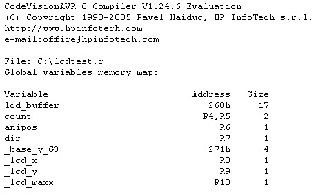
Example .MAP File
6) Printing
I thought it would be a nice feature to be able to print out the information retrieved
from the MCU. Visual Basic does not have any include any helper libraries to simplify
pritning. Each printed page has to be manually created and then sent to the printer.
The Visual Basic printing event triggers printing and the property HasMorePages
manually indicates when there are more pages to print. The first printed page is
the data registers. Data registers did not take up the entire page so I also included
the MCU state information. The next page is the I/O registers. I/O registers are
only one byte long so some of the columns of the other data types did not need to
be included, allowing two columns of I/O registers (all 64 I/O registers) to be
printed on the page. All other pages contain the memory information. To save trees,
only the memory locations used by variables in the map file are printed.
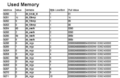
Sample From Print Out
7) Config File
I wanted the program to be distributed by a single file, the program's binary. However,
I wanted changes to the communications port number and I/O register to be saved.
When any configuration changes are made, I save them back to a config file. If the
config file does not exist when the program is run, a new config file is automatically
generated with the default I/O register names and comm one as the communication
port. The config file is an XML file so that the data can be stored in a readable
manner and standard classes can be used to the read the file.
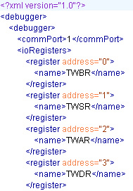
Sample from config file
Results
1) Speed
The program takes approximately 42 seconds to read all values from memory and 3
seconds to read all values from the registers. A feature was added to only
read values from memory locations used in the map file to prevent having to read
all of memory. Based on only the speed of the communications port, the program
could take only 25 seconds (2048x30x8/19200). The reason this speed was not
achieved is discussed above. A status bar is displayed on the screen when
reading from memory to indicate the overall progress of the read.
2) Resources
The program is not CPU intensive as there are only short bursts of CPU usage.
The program uses about 14MB of memory at startup and after use can reach usages
of about 24MB. Resource usage is not great enough to cause computer performance
issues. Threads are used to read from the MCU to allow the program to be minimized
while the data is being retrieved.
3) Accuracy
This program has been tested using the example target programs available on the
Cornell University ECE 476 website. For all programs, this debugger program produces
the same output as the debugger created by Bruce Land. Since I did not fully test Bruce
Land's program, I can only state that this program produces the same output but
will make no claim on the accuracy of both programs.
4) Safety
No damage to any microcontrollers has been experienced while testing the program.
I have also not experienced any problems switching from debug mode back to running
the target program. However, I do not guarantee that there will never be any damage
to the microcontroller while using this program.
5) Usability
Use of the program by students in next semester's ECE 476 course will determine if
the goal to provide an easy to user interface was accomplished.
Conclusions
The program performs all the required functionality and should be easy enough for
future generations of students to use. Testing took up the majority of time during
development of the program. Other than getting used to Visual Basic, there were no
major difficulties in development.
All the source code was written by myself and time was taken to document the code
and make it easy to read. This should enable easier maintenace of the program.
Source Code/Binary
Most current version is available for download at: https://gforge.cis.cornell.edu/projects/mega32debug/. This document, the user manual, and the source code in PDF form is also available on the site.