An IR Muscle Contraction Sensor
Raghav Subramaniam
Cornell University
Objective
This semester, I built an IR muscle contraction sensor (IR sensor). It applies IR light and measures the reflectance of the light from the user’s bicep in order to show the onsets and force of the user’s bicep contractions. The goals of the project were to create a cheap, less-invasive alternative to the traditional EMG electrodes; to compare the IR sensor to its EMG counterpart (EMG sensor); and to develop an understanding for the physiology of muscle contractions.
Biological Background
With my sensor, I focused on isometric contractions, contractions in which the length of the muscle does not change when force is being applied. For example, clenching a fist causes an isometric bicep contraction. It is made of three parts: a quick initial lengthening of the bicep, a period of constant muscle force and length, and then a slow release of the muscle. During the initial lengthening of the muscle, the actin and myosin fibers in the muscle stretch out. This reduces the reflectance of IR light from the muscle. During the release of the muscle, blood flows relatively slowly back into the muscle, giving a higher reflectance of IR light from the muscle, due to the blood flow.
Design and Methodology
I built both an IR sensor and an EMG sensor, and I compared the output of the IR sensor to the output of the EMG sensor. My goal was similarity between the outputs: this means the IR sensor is a viable alternative to the EMG sensor.
The IR sensor has two parts: the sensor itself, which is strapped to the bicep, and the signal processing circuitry. The sensor was built to reduce motion artifacts, a major source of noise in the IR output signal. The sensor is made of an IR LED and an IR phototransistor soldered to a small piece of breadboard, then outfitted with foam and a velcro strap to provide a tight fit with the forearm. I had to ensure that both the LED and the phototransistor must “face” the bicep muscle, and that all light transmitted from the LED must bounce off the bicep before being sensed by the phototransistor. The foam enforced this. The signal processing circuitry is simple, consisting of a bandpass filter with gain. The RC time constants were chosen such that the signal from the initial lengthening of the muscle dies out before the signal from the blood flow back into the muscle starts, and such that motion artifacts and external optical noise were minimized. Variable gain was used because the strength of the IR sensor’s signal changed with different placements on the bicep.
The EMG sensor is more complex. It uses two electrodes attached with adhesive to the forearm to pick up electrical potential generated by the muscle contractions. The difference between the potentials measured by each electrode are used to generate the output signal. These two inputs are fed to a differential amplifier and the resulting signal is bandpass filtered, to reduce noise from electromagnetic interference. The part of the EMG signal processing circuit attached to the user (i.e. the differential amplifier) must be electrically decoupled from the part of the circuit attached to the DC power source. To do this, I used four AA batteries and an optocoupler.
To test both sensors, I used a variety of muscle contraction patterns. Specifically, I used a series of equally-spaced short contractions of equal strength, a series of equally-spaced short contractions of increasing strength, and a long, held contraction.
Following are circuit schematics and output waveforms.
Circuit Schematics
fig. 1
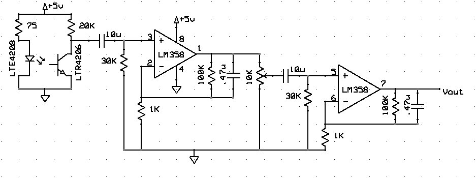
This is the entire circuit for the IR sensor. It includes the sensor itself and a bandpass filter with adjustable gain.
fig. 2
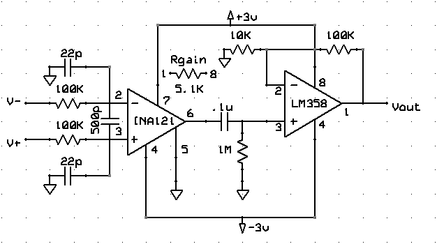
This is the first stage of the EMG sensor’s signal processing circuitry. It is a differential amplifier. It amplifies the difference between the two EMG electrodes’ signals, and then bandpass filters the result. Power for this stage of the circuit comes from four AA batteries.
fig. 3
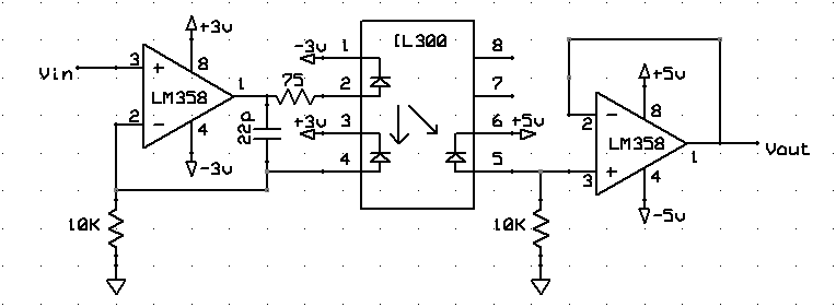
This is the second stage of the EMG sensor’s signal processing circuitry. It electrically decouples the circuitry connected to the user from the circuitry connected to a DC power source, mainly as a safety consideration. The left side of this stage (before the optocoupler itself) is powered by four AA batteries, and the right side (after the optocoupler) is powered by a 5V DC source.
Results
fig. 4
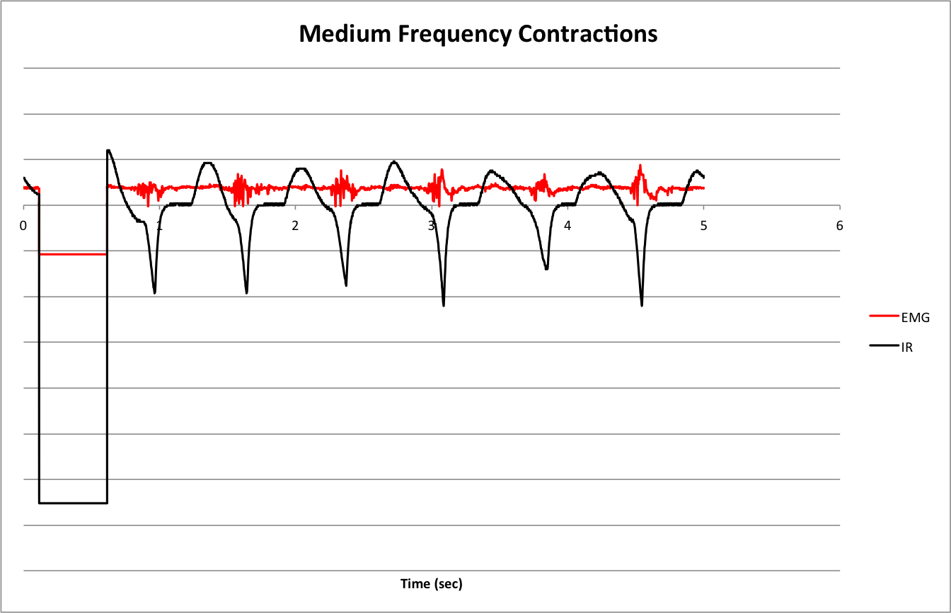
To get this waveform, I contracted my bicep in evenly-spaced pulses of equal force. The sharp downward spikes in the IR waveform correspond to the onsets of the isometric bicep contractions. This spike has the same width as the pulse in the EMG waveform. There is a consistent correlation between the IR spikes and the EMG pulses. However, the IR sensor exhibits a slight delay compared to the EMG sensor, and this is reflected in the waveforms.
fig. 5
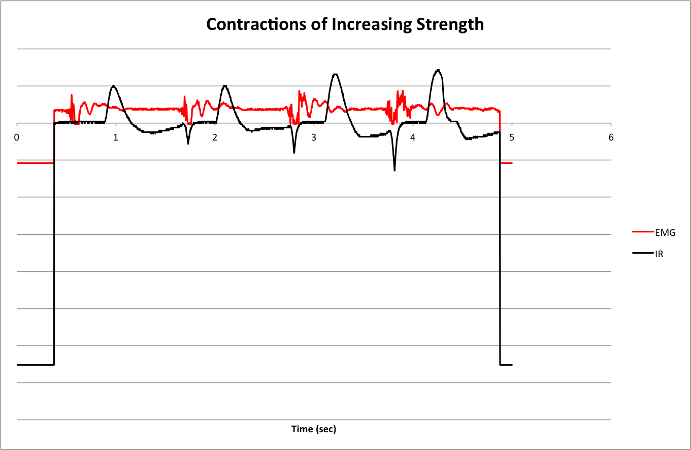
To get this waveform, I contracted my bicep in evenly-spaced pulses of increasing force. The IR waveform shows a direct proportionality between the height of the IR spikes and the force of the muscle contraction. The correspondence is more difficult to see in the EMG waveform.
fig. 6
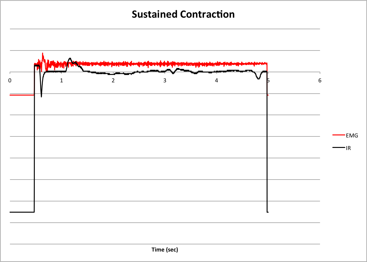
To get this waveform, I contracted my bicep once and held the contraction. The IR waveform shows one of the flaws of the IR sensor, motion artifacts. These are the bumps at about 1 second, 3.5 seconds, and 4.75 seconds. Motion artifacts are much more evident on longer muscle contractions.
Next Steps
In its current iteration, the IR sensor works well for determining the onsets of fast muscle contractions. It is not as good for held contractions or for accurately determining the force of contractions. There are several steps I can take to improve the sensor.
Miniaturization of the sensor would improve the project in several ways. First of all, a smaller sensor would be able to be fitted tighter to the user’s body, reducing motion artifacts and giving a cleaner output signal. It would allow for the measurement of the contractions of smaller muscles, such as the muscles in the anterior forearm that control fine finger movements or the ocular muscles that control blinking. These muscles are capable of contractions of higher frequencies than the bicep is, so miniaturization would allow me to examine the limits of the speed of my sensor.
Finally, I’d like to be able to remotely sense muscle contractions. By measuring the absorption of the IR light instead of the reflectance, I can ignore factors such as imperfections in the skin and the presence of hair. So, a sensor consisting of an IR laser and a bank of IR phototransistors may be able to remotely sense contractions.
Conclusion
This IR muscle contraction sensor succeeds in measuring the onsets of muscle contractions, and, to some extent, the force of these contractions. Its output more or less matches that of the more traditional EMG for short, isometric contractions, and the sensor is less invasive and less susceptible to electromagnetic radiation. However, motion artifacts remain an issue. With further improvement, IR muscle sensing can be a viable alternative to EMG muscle sensing.
References
Chianura, Alessio, and Mario Giardini. “An electrooptical muscle contraction sensor.” Med Biol Eng Comput. 48. (2010): 731–734. Web. 16 May. 2013. http://link.springer.com/content/pdf/10.1007%2Fs11517-010-0626-x.pdf.
Land, Bruce. “ECE 5030.” Cornell University School of Electrical and Computer Engineering. 07 May 2013. Web. 16 May 2013. http://people.ece.cornell.edu/land/courses/ece5030/.