Introduction
Four years of repeated drought has devastated California’s agriculture, industry, and life style. With no end in sight to the current drought, Governor Jerry Brown issued an executive order for a mandatory 25% reduction by all urban water users. Interestingly, this order only applies to urban life even though agriculture accounts for roughly three quarters of Californians’ water usage. Urban water users need a device that can help them reduce water usage in a smart and user friendly way.
In the Internet of Things age, connecting web data to our daily lives is the name of the game. By utilizing web data, we can make smarter systems, especially when it comes to water conservation. My independent research project was to answer Governor Brown’s call for water conservation in urban life. Using IoT concepts, the Smart Sprinkler addresses the problems of the current archaic irrigation systems present in most residential areas.
A typical irrigation system waters a residence’s landscape at the same time each day. On too many occasions I have seen sprinklers going off while it is raining. This huge waste of urban water can be totally avoided with a simple device. The Smart Sprinkler solves this issue by analyzing both internet weather data and soil moisture each day. Based on the soil moisture and weather forecast, the Smart Sprinkler will only turn on the irrigation system when the soil is dry and there is no rain in the weather forecast. This device can help residents meet Governor Brown’s mandatory water reduction and only requires an internet connection.
High Level Design
Rationale
The goal for this project was to give residents a cheap and simple way to monitor and reduce the water used for irrigation. Without having to actively think about conserving water, users can rely on the Smart Sprinkler to do their share of water conservation. The Smart Sprinkler uses only a few parts and small program to accomplish its water savings goal.
Logical Structure
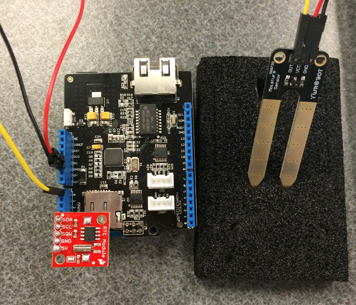
The Smart Sprinkler is split up into a few major hardware systems. The computing system behind the device is the Arduino Uno R3, which uses the ATMega328 microcontroller as its processor. On top of the Arduino, an Ethernet shield from SeeedStudio was used to download weather data from the web. A two-pronged moisture sensor relayed soil moisture data to the Arduino for processing. In addition, a DS1307 real time clock module acted as the device’s internal clock and calendar. On a higher level, the device interacts with the user’s computer through the Arduino’s UART interface.
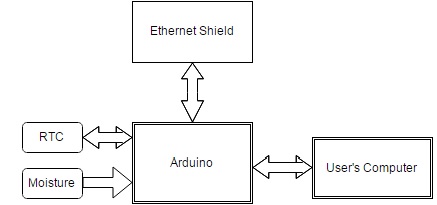
System Block Diagram
On a software level, the Arduino sketch is organized into a state machine. Each state is required to perform different functions and execute different methods throughout the program. The program states are as follows: Menu state, check time state, measure moisture state, and download weather data state.

Program State Diagram
Hardware and Program Design
Hardware Design
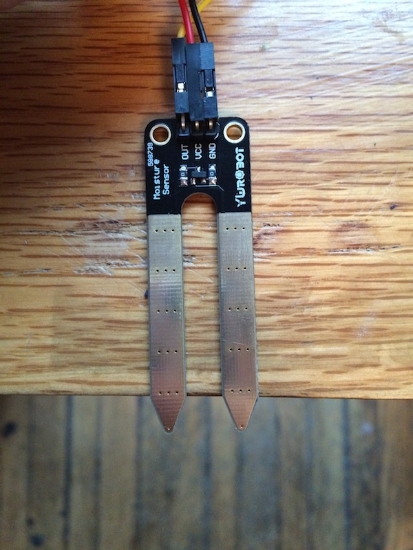
Moisture Sensor
Soil moisture can be measured very simply with just two electrodes. These two electrodes are placed in the soil and a voltage is applied across. The output value is sent to the Arduino’s analog to digital converter (ADC) and analyzed by the program. In air, the moisture sensor will output 0 because there is no current flowing between the electrodes. In water, the moisture sensor will output its highest value because there is the highest current possible between the two electrodes. Using these two boundary conditions, values for dry, moist, and wet soil were implemented into the program. These values helped the device decide when it is appropriate to activate the irrigation system. As shown below, the moisture sensor output is wired to Arduino’s analog input 0, Arduino 5V, and Arduino GND.
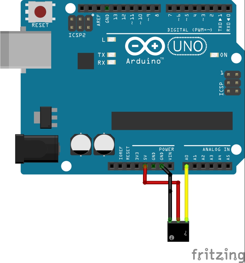
Moisture Sensor Wiring Diagram
Real Time Clock Module
The DS1307 real time clock (RTC) module keeps track of the current year, month, day as well as the current time. The device used a SparkFun breakout of the RTC. To access the RTC module, I2C protocol is used by the Arduino to query and set the current date and time. The wiring diagram below shows how this module is connected to the Arduino. I2C clock pin (SCL) is wired to analog input 5, I2C data pin (SDA) is wired to analog pin 4, and power and ground are connected to the Arduino’s 5V and GND pins.
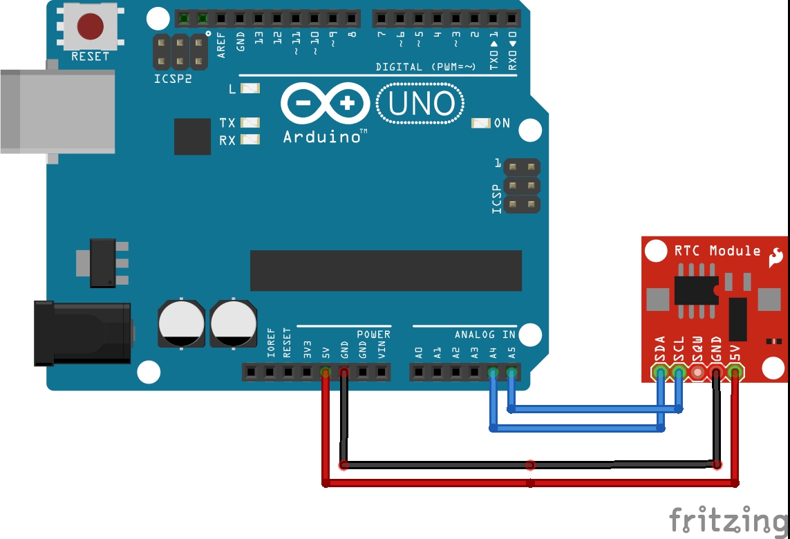
Real Time Clock Module Wiring Diagram
Ethernet Shield
The SeeedStudio Ethernet Shield V2 includes all the necessary hardware components to host a web server and query a web client for data. The shield also contains a micro SD card socket that can be used for data logging purposes. Five pins are used by the Ethernet shield to communicate with the Arduino. Pin D4 is used to select and deselect the SD card, D10 is used to select the Ethernet chip, D11 is the SPI MOSI pin, D12 is the SPI MISO pin, and D13 is the SPI SCK pin. Both the Ethernet chip and SD card communicate with the Arduino via SPI bus; therefore, pins D10 and D4 are chip select pins and cannot be used as general I/O.
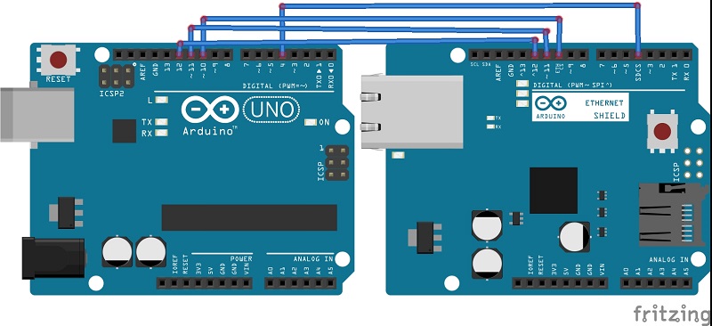
Ethernet Shield Wiring Diagram
Program Design
Menu State
In the menu state, the user is prompted with device parameters. This state is reachable only on device reset or by pressing the “menu” pushbutton. In the menu, the user is prompted, through UART interface, to enter important device parameters. First, the user needs to enter the current date and time. This information is then transferred to the real time clock (RTC) module through I2C, which now starts keeping track of the current date and time. After the RTC receives the current time, the user enters the time he wants the device to check soil moisture, download weather data, and turn on irrigation. Next, the user enters his location, which is imperative for the device’s operation. This location will be used when querying the internet for local weather data. After inputting all necessary information, the program enters the check time state.
Check Time State
The program spends most of its time in the check time state. In this state, the program continually queries the RTC, using the RTC and Wire Arduino libraries, for the current time. When this current time equals the user-inputted check time, the program advances to the next state to check the soil moisture level.
Measure Moisture State
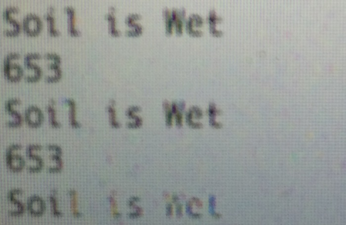
The majority of the program’s computation happens once the current time reaches the check time. In the check moisture state, the program uses the analog to digital converter on the Arduino to read a voltage value from the moisture sensor. The returned value is then determined to be dry soil, moist soil, or wet soil.
Download Weather Data State
Simply measuring the soil’s moisture level can provide some water savings by only irrigating when the soil is dry; however, the idea of this project is to make a smarter irrigation system. In this state, the day’s weather forecast is downloaded and then analyzed by the program to avoid irrigating the landscape when rain is forecasted.
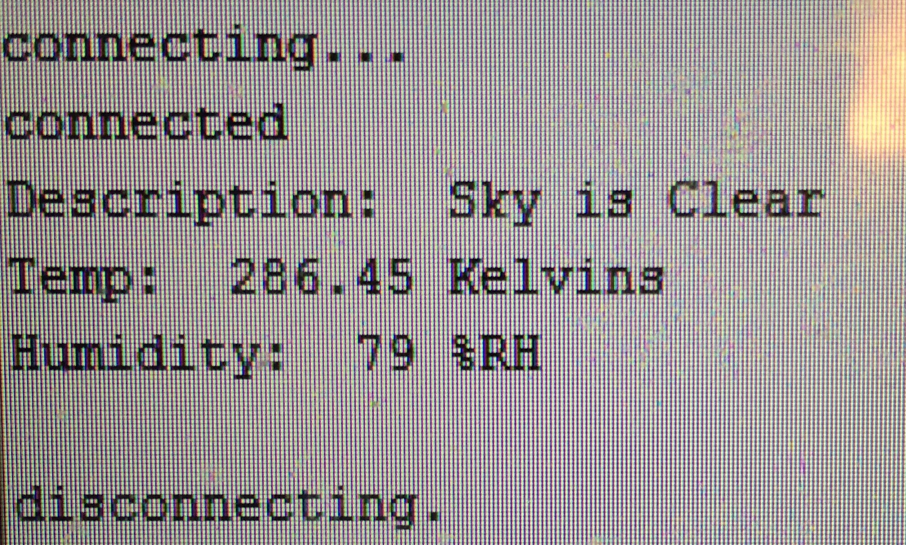
When the program enters this state, it takes the user-inputted location string as an argument for the connectToServer method. This method connects to the Open Weather Map API server at api.openweathermap.org using a GET request. In this GET request, the location string is added to the request’s URL. This URL is then sent to the Ethernet chip using the EthernetV2 Arduino library. If the connection is successful, the program searches downloaded data for rain in the forecast. The Open Weather Map API uses status codes to denote the forecast type. For any rain in the forecast, the API returns a status code in the 500 range. If the rain status code is found, the program alerts the user through the UART interface and turns on a red LED, which denotes an “irrigation off” signal. This signal can be used, depending on the user’s specific system, to disable an irrigation system or to drive a solenoid to manually turn off the system.
Once the irrigation decision has been made, the program returns to the check time state and waits until the check time has been reached for the next day. For special circumstances, a pushbutton is also implemented where a user can override the program and manually turn on irrigation.
Results and Testing
Overall, the device worked exactly as intended. The device could successfully be programmed by a user, continually query for the inputted check time, measure moisture and download weather data at that time, and make an irrigation decision based on those values. Throughout the development of the device, each subsystem was tested separately to ensure correct functionality. A simple ADC program tested the functionality of the moisture sensor and was used to calibrate the various moisture levels. For the Ethernet shield, an example program from SeeedStudio was used and then altered for my device’s specific needs. The RTC was tested using sample code in the module’s library.
Calibrating the Moisture Sensor in Air
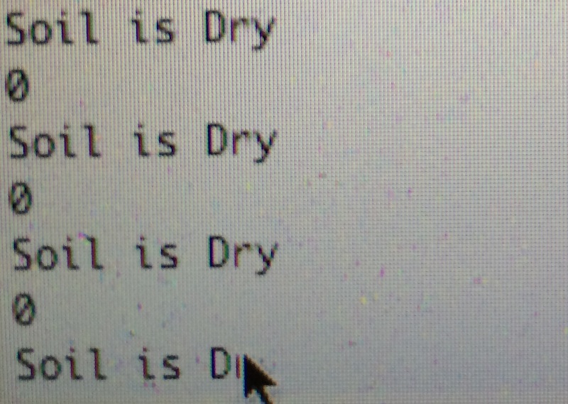
Moisture Sensor Air Calibration Values
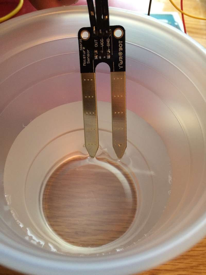
Calibrating the Moisture Sensor in Water
Moisture Sensor Water Calibration Values
Ethernet Shield Weather Data Test
Once each subsystem was thoroughly tested, systems were sequentially added to the main program. First, I made sure the Ethernet shield could correctly download weather data and printed that data to the UART interface. For initial testing, a location variable was hardcoded into the GET request’s URL. When the Ethernet shield was functioning, I wrote the code to parse the data and set an irrigate boolean variable. Next, the moisture sensor was implemented and tested along with the Ethernet shield to ensure correct functionality with the two systems working together. The last two systems implemented were the RTC module and user menu. These two systems were simple to add to the main program because they only required adding two new states. For the menu state, I simply had to remove the hardcoded values from the program and take the user inputted values for location, current date and time, and check time and add them to the program.
Conclusion and Future Versions
Overall, the Smart Sprinkler can help reduce residential water usage in a simple and cheap manner. According to epa.gov, the average American household uses 106 gallons of water per day for outdoor uses. Every day that it rains, this amount of water can be conserved for other uses. Unfortunately, an estimated 50% of outdoor water usage is wasted from inefficient water methods. Coupling the Smart Sprinkler with a more advanced drip irrigation system can curb water waste even further.
My device helped me learn about IoT systems and their uses in our daily lives. Throughout the design process, I continually thought of new improvements for my device that can make it even more applicable to current life. In the future, I have a couple new design ideas that will make my device much more user friendly and effective device.
First, I want to remove the Ethernet shield and add a WiFi chip to make the system wireless. These chips are very cheap and already have Arduino libraries available. The ESP8266 WiFi SDK is only $5 dollars in hardware and a great choice for use in IoT projects. Additionally, I want to make use of a smartphone interface for the device. Having the device connected to a user’s computer to make changes or check the system status is not as convenient as a phone app would be. My final, and possibly most important, future design choice is to make use of ATmega low power modes. My current program continually spins in the check time state with all processor systems on, which is a large waste of power. In the future, I am going to implement an RTC module, such as the DS1337, that has programmable alarms. These alarms can be used to wake up an ATmega processor that is in a low power mode. This way, only the RTC is consuming power all day, and the processor can sleep when it is not being used.