Phong Shading and Gouraud Shading
MEng. project '96By Xichun Jennifer Guo
Advisor: Professor Bruce Land
Table of Contents
Introduction
In this project I implemented Phong Shading and Gouraud Shading on Phong Reflection Model.
The "standard" reflection model in computer graphics that compromises between acceptable results and processing cost is the Phong model. The Phong model describes the interaction of light with a surface, in terms of the properties of the surface and the nature of the incident light. The reflection model is the basic factor in the look of a three dimensional shaded object. It enables a two dimensional screen projection of an object to look real. The Phong model reflected light in terms of a diffuse and specular component together with an ambient term. The intensity of a point on a surface is taken to be the linear combination of these three components.
A. Diffuse Reflection
Most objects we see around us do not emit light of their own. Rather they absorb daylight, or light emitted from an artificial source, and reflect part of it. The reflection is due to molecular interaction between the incident light and the surface material. A surface reflects coloured light when illuminated by white light and the coloured reflected light is due to diffuse reflection. A surface that is a perfect diffuser scatters light equally in all directions. This means that the amount of reflected light seen by the viewer does not depend on the viewer's position. The intensity of diffused light is given by Lambert's Law:
Id = IiKdcosA (1.1)
Ii is the intensity of the light source. A is the angle between the surface normal and a line from the surface point to the light source. The angle varies between 0 and 90 degrees. Kd is a constant between 0 and 1, which is an approximation to the diffuse reflectivity which depends on the nature of the material and the wavelenght of the incident light. Equation 1.1 can be written as the dot product of two unit vector:
Id = IiKd(L.N) (1.2)
where N is the surface normal and L is the direction of vector from the light source to the point on the surface. If there is more than one light source then:  (1.3)
(1.3)
B. Ambient Light
Ambient light is the result of multiple reflections from walls and objects, and is incident on a surface from all directions. It is modelled as a constant term for a particular object using a constant ambient reflection coeffient:
I = IaKa (1.4)
Where Ia is the intensity of the ambient light and Ka is the ambient reflection coefficient. Ambient light originates from the interaction of diffuse reflection from all the surfaces in the scene.
C. Specular Reflection
Most surfaces in real life are not perfectly diffusers of the light and usually have some degree of glossiness. Light reflected from a glossy surfac
e tends to leave the surface along vector R , where R is such that incident angle is equal to reflection angle. The degree of specular reflection seen by the viewer depends on the viewing direction. For a perfect glossy surface, all
the light is reflected along the mirror direction. The area over which specular reflection is seen is commonly referred to as a highlight and this is an important aspect of Phong Shading: the color of the specularly reflected light is different from that of the diffuse reflected light. In simple models of specular reflection the specular component is assumed to be the color of the light source. The linear combination of the above three components: diffuse, ambient and specular is as follows:

That is :
 (1.5)
(1.5)
Where B is the angle between the viewing vector V and the reflection vector R . Ks is the specular reflection coefficient, usually taken to be a material-dependent constant. For a perfect reflector n is infinite. A very glossy surface produces a small highlight area and n is large.
D. Geometric Consideration
The expense of Equation 1.5 can be considerably reduced by making some geometric assumptions and approximations. If the light source and viewpoint are considered to be at infinity then L and V are constant over the domain of the scene. The vector R is expensive to calculate, it is better to use H. The specular term then becomes a function of N.H rather than R.V. H is the unit normal to a hypothetical surface that is oriented in a direction halfway between the light direction vector L and the viewing vector V:
H = (L + V) /2 (1.6)
The equation 1.5 becomes:
 (1.7)
(1.7)
In this project, I would like to make the light postion changable and show the effect of shading for the different light position, so this assumption has not been used.
Implementation
Click here to get the source code.
I apply the above Phong reflection model to a dodecahedron model to show the advantage and disadvantage of Phong Shading and Gouraud Shading.
A. Gouraud Shading :
 (2.1)
(2.1)
In Gouraud Shading, the intensity at each vertex of the polygon is first calculated by applying equation 1.7. The normal N used in this equation is the vertex normal which is calculated as the average of the normals of the polygons that share the vertex. This is an important feature of the Gouraud Shading and the vertex normal is an approximation to the true normal of the surface at that point. The intensities at the edge of each scan line are calculated from the vertex intensities and the intensities along a scan line from these. The interpolation equations are as follows:


 (2.2)
(2.2)
For computational efficiency these equations are often implemented as incremental calculations. The intensity of one pixel can be calculated from the previous pixel according to the increment of intensity:

 (2.3)
(2.3)
The inplementation of the Gouraud Shading is as follows:
   deltaI = (i2 - i1) / (x2 - x1);

   for (xx = x1; xx < x2; xx++)

    	    {	int offset = row * CScene.screenW + xx;

    	    	if (z < CScene.zBuf[offset])

    	    	{   CScene.zBuf[offset] = z;

    	    	    CScene.frameBuf[offset] = i1;

    	    	}

    	    	z += deltaZ;	i1 += deltaI;

    	    }
Where CScene.ZBuf is the data structure to store the depth of the pixel for hidden-surface removal (I will discuss this later). And CScene.frameBuf is the buffer to store the pixle value. The above code is the implementation for one active scan line. In Gouraud Shading anomalies can appear in animated sequences because the intensity interpolation is carried out in screen coordinates from vertex normals calculated in world coordinate. No highlight is smaller than a polygon.
B. Phong Shading:
 (2.4)
(2.4)
Phong Shading overcomes some of the disadvantages of Gouraud Shading and specular reflection can be successfully incorporated in the scheme. The first stage in the process is the same as for the Gouraud Shading - for any polygon we evaluate the vertex normals. For each scan line in the polygon we evaluate by linear intrepolation the normal vectors at the end of each line. These two vectors Na and Nb are then used to interpolate Ns. we thus derive a normal vector for each point or pixel on the polygon that is an approximation to the real normal on the curved surface approximated by the polygon. Ns , the interpolated normal vector, is then used in the intensity calculation. The vector interpolation tends to restore the curvature of the original surface that has been approximated by a polygon mesh. We have :


 (2.5)
(2.5)
These are vector equations that would each be implemented as a set of three equations, one for each of the components of the vectors in world space. This makes the Phong Shading interpolation phase three times as expensive as Gouraud Shading. In addition there is an application of the Phong model intensity equation at every pixel. The incremental computation is also used for the intensity interpolation:


 (2.6)
(2.6)
The implementation of Phong Shading is as follows:
    for (xx = x1; xx < x2; xx++)

    	    {	int offset = row * CScene.screenW + xx;

    	    	if (z < CScene.zBuf[offset])

    	    	{   CScene.zBuf[offset] = z;

		    pt = face.findPtInWC(u,v);

		    float Ival = face.ptIntensity;

		    CScene.frameBuf[offset] = Ival;< BR>
    	    	}

		u += deltaU;

    	    	z += deltaZ;

		p1.add(deltaPt);

    	    	n1.add(deltaN);

             } M
So in Phong Shading the attribute interpolated are the vertex normals, rather than vertex intensities. Interpolation of normal allows highlights smaller than a polygon.
C. Hidden-Surface Removal
Both in the implementation of Phong Shading and Gouraud Shading, the Z-buffer algorithm is used for hidden-sufrace removal. We can imagine a three dimensional screen space, where the (x,y) values are pixel coordinate and the z value is the interpolated viewing space depth. For each pixel(x,y), search through the associateed z values of each interior polygon points to find that point with the minimum z value. This search is conveniently implementd by using Z-buffer that holds for a current (x,y) the smallest z value so far encountered. During the processing of a polygon, we either write the intensity of a point into the frame buffer or not, depending on if the depth z of the current point is less than the depth so far encountered as recorded in the Z-buffer. The Z-buffer algorithm is as follows:
  while (face != null)

    {

        Construct edgelist for the current polygon, for each eage calculate
        the value of x, z and I for each scan line.

	for y := Ymin to Ymax do

	    for X := Xmin to Xmax do

		if z < CScene.zbuf[offset]

		{

			CScene.zbuf[offset] = z;

			CScene.frameBuf[offset] = Ival;

                }
             }}

	face = face.next;

    }
So in principle, for each polygon, we compute: (1): the (x,y) value of the interior pixels. (2) the z depth for each (x,y) and (3) the intensity I for each point. The main advantage of the Z-buffer algorithm is its simplicity of implementation. Its main disadvantage is the amount of memory required for the Z-buffer.
During the implementation of Z-buffer hidden surface removal in Phong Shading and Gouraud Shading, the rasterizing of polygon is to be implemented to fill the polygons with the pixel value. For each polygon, while we are concerning with shading, that is to find the pixel coordinates of interior points and assigning to these a value calculated using the above two shading techniques, an edgelist is used for each polygon. This is done by using an array of linked list, with an element for each scan line. Each edge of the polygon is rasterized in turn, and the x coordinate of each pixel thus generated is inserted into the linked list corresponding to the value of y. Each of the linked lists is then sorted in order of increasing x. Filling in of a polygon is thus achieved by, for each scan line, taking successive pairs of x values and filling in between them:
public class CEdgeTableEntry // edge table for polyFill.The above is the structure for one edge of a polygon. The next pointer points to the next edge. All the necessary information of a edge for shading is kept in this class. Another class public class CActiveEdgeTable is used to keep the current scan line while during the process of filling the polygon. A quick sort algorithm is used for the sorting of the filling segments according to the x coordinate.
{ public:
short upperY; // y-coord of the upper endpt of the edge
float x; // current x-coord
float invSlope; // inverse of slope of the edge
float depth; // depth of point at (x,y) (in WC)
float deltaD; // depth increment along the edge
float intensity; // intensity at (x,y)
float deltaI; // intensity increment along the edge
vector normal; // normal at point (x,y) ( = at (Ux,Uy) in NDC)
vector deltaN; // normal increment
CEdgeTableEntry next;
}
D. Camera
 (2.7)
(2.7)
To project a three dimensional model onto a two dimensional viewing space to implement Phong Shading and Gouraud Shading, a camera is to be defined:
public class CCamera

{   float	COP;	// center of perjection (eye position)

		// It is on -VPN dir in view coord w/ a distance behind VRP

    int	screenW, screenH;

    float	FOV;		// field of view. Like that in zoom lens


    CPoint3D	VRP;		// view reference point = origin of VC

    CVector	VPN;		// view plane normal. also an axis in VC

    CVector	VPU, VPV;	// u- & v- axies in VC

    CVector	VUP;		// the Up dir in VC. Not required perp. to VPN

    CPoint3D	eyeInWC;	// used for back face removal & shading

    CMatrix3D	Mw_v;		// mapping from WC to VC

    CMatrix3D	Mv_w;		// mapping from VC to WC. Used to calculate

				// eyeInWC and dir from eye to pt in WC

}
As shown in Figure 2.7, the center of projection is at (0,0,6) and the view plane is centered at (0,0,1) in this project.
VRP: Set the view reference point to [x,y,z] in world coordinates. Here is the view plane origin. The default value in this project is [0,0,1].
COP: Set the center of perspective projection to be a distance behind the VRP in viewing coordinates. The default COP value in this project is 5. So the center of projection is (0,0,6).
VPN: Set the view plane normal to vector [dx,dy,dz] in world coordinates. The default value is [0,0,-1].
VUP: Set the view up direction to [dx,dy,dz] in world coordinates. The default value is [0,1,0].
So VPN, VUP form the three dimension left-handed coordinate system to build the view space.
E. Light and Model
The class defined for the light is as follows:
class CLight
{   int 	maxLightNo, lightNo;

    CPtLight[]	ptLight;

    float 	Ia;			// ambient light intensity;
    boolean	lightOnMode;


    public CLight()

    public void updateLight(float x, float y, float z, float Ip, float Ia)

    public void setIa(float Ia)

    public void addLight(double x, double y, double z, double Ip)

}
class CPtLight

{   CPoint3D	at;	// in WC

    float	Ip;	// intensity

}
The default light position is (0,0,20). Through these methords, the light intensity and light position can be updated.
 (2.8)
(2.8)
A dodecahedron model (Figure 2.8) is used for Phong Shading and Gouraud Shading. The model is centered at the origin and scaled to fit inside a unit sphere. Dodecahedron is modeled as a collection of vertices, connected by a set of edges to build the faces of the dodecahedron. The model can be rotated along X, Y and Z axis from the original model centered at (0,0,0) by the angle defined by the user. The light position and the light intensity Ia and Ip can be adjusted to show the effect of light on Shading. And the coefficient Ka, Ks and Kd can be modified to simulate different material and scene for Shading.
Results
Click here to run the Shading program.
The following is the demo to show the comparision of Phong Shading and Gouraud Shading with Ka = 0.2, Ks = 0.5 and Kd = 0.5.
Demo A to E is the Phong Shading and Gouraud Shading for n = 1, 10, 25,100 and 800. We can see in Phong Shading, with the decrement of the glossiness of the surface, the highlight become bigger. The light position is in (0,0,2).
A. The following is the Phong Shading and Gouraud Shading for light position (0,0,2) and n = 800:

B. The following is the Phong Shading and Gouraud Shading for light position (0,0,2) and n = 100:
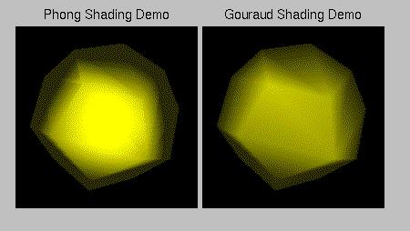
C. The following is the Phong Shading and Gouraud Shading for light position (0,0,2) and n = 25:
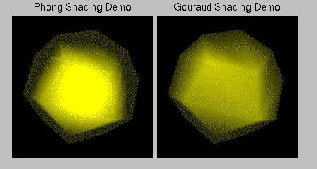
D. The following is the Phong Shading and Gouraud Shading for light position (0,0,2) and n = 10:
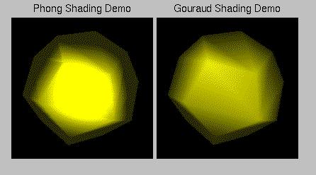
E. The following is the Phong Shading and Gouraud Shading for light position (0,0,2) and n = 1:

F. The following is the Phong Shading and Gouraud Shading for light position (2,2,2) and n = 100:

G. The following is Phong Shading and Gouraud Shading for light positon (20,0,20) and n = 100:
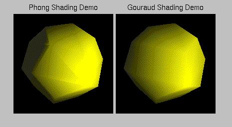
H. The following is Phong Shading and Gouraud Shading for light positon (2,0,2) and n = 100:
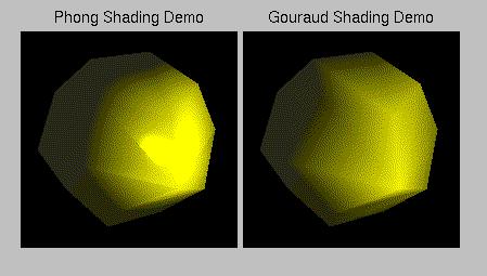
Note that as n increases the highlight on the Phong Shading becomes smaller, but the Gouraud Shading does not because the highlight is smaller than the polygon.
Conclusion
Gouraud Shading is effective for shading surfaces which reflect light diffusely. Specular reflections can be modelled using Gouraud Shading, but the shape of the specluar highlight produced is dependent on the relative positions of the underlying polygons. The advantage of Gouraud shading is that it is computationally the less expensive of the two model, only requring the evaluation of the intensity equation at the polygon vertices, and then bilinear interpolation of these values for each pixels.
Phong Shading produces highlights which are much less dependent on the underlying polygons. However, more calculation are required, involving the interpolation of the surface normal and the evaluation of the intensity function for each pixel.
Acknowledgements
I would like to express my sincere appreciation to Professor Bruce Land for providing the expert guides that is necessary to complete this work. Deep thanks to my friend Jing Li for his informative advice and friendly help. Special thanks to my sponsor who financially supported me to make this study at Cornell University possible. And thanks to my parents and all my friends.
References
[1] Francis S.Hill, Jr. "Computer Graphics" Macmillan Publishing Company, 1990.[2] Alan Watt, "3D Computer Graphics" Addison-Wesley Publishing Company, 1993.
[3] Gouraud shading
[4] Lighting and Shading
[5] Phong Shading
[6] Effects of Phong Shading
[7] The representation of Molecular Models: Rendering Techniques