A Simple CAD program
CS490 Spring 1998
by Hubert Siu
Introduction:
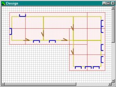
3D graphics has gained a lot of importance in the past few years, especially in design, modelling, and gaming. The purpose of this project is to make use of OpenGL libraries and MFC (Microsoft Foundation Class) libraries to create a 3D graphics application--a simple CAD program. This application allows a user to design a house in a 2D space, while able to view the 3D model on another window at the same time.Process:
1. Background:
Before starting on the project, I went through a few tutorials on MFC and OpenGL. A good tutorial for starting with MFC is the Scribble tutorial that comes with Visual C++. This tutorial helped me to understand how to build an application with all the basic requirements: load and save files, controlling the mouse, select from menu and toolbar, create dialog boxes, draw within a window, and more. OpenGL tutorials could be found online, and I went through the tutorials that can be found at DevCentral. These tutorials and sample programs gave me a good idea on a lot of essential part of the project: setting up the device context for OpenGL graphics, drawing 3D objects with lighting effects, setting up camera view on the 3D model, etc. Some other techniques, like texture mapping and optimizing the code for rendering speed, could be found in some reference book.2. The Interface:
After deciding to use a link list as the data structure for storing information, I started to modify the skeleton code generated by MFC AppWizard.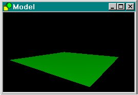 The
first task I planned to achieve was to edit the code so that I can only
have a single document open at a time while have 2 different views, with
one for designing and one for displaying the 3D model. I used the
project manager to generate a multiple document interface (MDI), but diable
the property of opening more than one file; instead, 2 views were created
when a file is opened or created instead of 1. The next thing I had
to do was to set up the drawable area (which is the base for the design)
with the grid lines in the design view and prepare the rendering context
for displaying the 3D object in the model view. Mouse control was
added afterwards so users can rotate the base in the model view. At this
point, the camera in the model view is fixed at the origin with the up
vector = (0, 1, 0), with viewing angle = 30 degrees. Basic menu items
are inserted, but they do not provide any function at this point.
The
first task I planned to achieve was to edit the code so that I can only
have a single document open at a time while have 2 different views, with
one for designing and one for displaying the 3D model. I used the
project manager to generate a multiple document interface (MDI), but diable
the property of opening more than one file; instead, 2 views were created
when a file is opened or created instead of 1. The next thing I had
to do was to set up the drawable area (which is the base for the design)
with the grid lines in the design view and prepare the rendering context
for displaying the 3D object in the model view. Mouse control was
added afterwards so users can rotate the base in the model view. At this
point, the camera in the model view is fixed at the origin with the up
vector = (0, 1, 0), with viewing angle = 30 degrees. Basic menu items
are inserted, but they do not provide any function at this point.
3. Room
The next step was to enable users to draw their own design. The first element that was implemented was the room.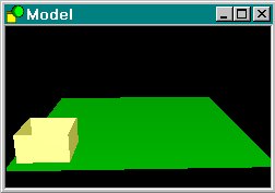 The
room is derived from a base class called CElement, which is derived from
CObject (defined by Microsoft). The purpose of using CObject as the
base class was because its member function Serialize reads and saves the
document data upon slight modification. A draw member function is
added to CElement for drawing the object in the design view, and the coordinates
are stored in a new element in a pointer array. The device context
object (CDC) provides member functions for drawing, such as LineTo and
Rectangle, and these functions were used to draw objects on the design
view. Different kinds of pen can be chosen to color the object.
While dragging, the pen style was set to PS_DOT and was changed to PS_SOLID
when an element is created so that dotted lines and solid lines can be
drawn depending on the condition. Once the design frame was capable
of drawing rooms, I started to work on the model view. The coordinates
for each rooms are stored under an array inside the document, and the model
view loads the values once the user has defined a new room. 8 polygons
are used for each room. Light position was adjust to make shade obviously
in all orientation. Restrictions are applied so that a room cannot
overlap another room. The height of the room is also fixed.
The
room is derived from a base class called CElement, which is derived from
CObject (defined by Microsoft). The purpose of using CObject as the
base class was because its member function Serialize reads and saves the
document data upon slight modification. A draw member function is
added to CElement for drawing the object in the design view, and the coordinates
are stored in a new element in a pointer array. The device context
object (CDC) provides member functions for drawing, such as LineTo and
Rectangle, and these functions were used to draw objects on the design
view. Different kinds of pen can be chosen to color the object.
While dragging, the pen style was set to PS_DOT and was changed to PS_SOLID
when an element is created so that dotted lines and solid lines can be
drawn depending on the condition. Once the design frame was capable
of drawing rooms, I started to work on the model view. The coordinates
for each rooms are stored under an array inside the document, and the model
view loads the values once the user has defined a new room. 8 polygons
are used for each room. Light position was adjust to make shade obviously
in all orientation. Restrictions are applied so that a room cannot
overlap another room. The height of the room is also fixed.
4. Door
Door and window are the next two elements that were added. Their sizes are fixed, because for rendering same objects in OpenGL, display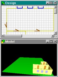 lists can be used to improve performance. Both door and window elements
also have CElement as their base class. 2 polygons are used for each
element. The window and door drawing functions for the design view
were added, as well as their own Serialize and draw member function.
The pointer array that stores the room element is also used to store new
door and window elements. When creating a door or a window, a small
box with dotted line is created when the left mouse buttons is down.
A door or window will not be created if that box does not intersect any
of the room element in the link list, nor it will be created if the element
intersects with a door/window element in the list. If the element
selected is successfully created in the design view, it should also appear
in the model view instantly.
lists can be used to improve performance. Both door and window elements
also have CElement as their base class. 2 polygons are used for each
element. The window and door drawing functions for the design view
were added, as well as their own Serialize and draw member function.
The pointer array that stores the room element is also used to store new
door and window elements. When creating a door or a window, a small
box with dotted line is created when the left mouse buttons is down.
A door or window will not be created if that box does not intersect any
of the room element in the link list, nor it will be created if the element
intersects with a door/window element in the list. If the element
selected is successfully created in the design view, it should also appear
in the model view instantly.
5. Transparent
Before addding the roof component, a transparent function for the 3D model was added. This was done by changing the alpha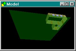 component
to a value smaller than 1 and enabling blending. The color of a pixel
is the combination of source color based on the alpha value and the destination
color based on the value of (1 - alpha value). Transparency will
not show up until the program enables the blending function. The
screen shot on the right was taken when the camera was located on the bottom
of the model, below the base. A button on the tool bar allows the
user to toggle between on and off for transparency. The speed will
be decreased when transparency is on, since more calculation has to be
performed. Note that there is a big difference in performance between
turning off the blending function and setting the alpha value of 1.
component
to a value smaller than 1 and enabling blending. The color of a pixel
is the combination of source color based on the alpha value and the destination
color based on the value of (1 - alpha value). Transparency will
not show up until the program enables the blending function. The
screen shot on the right was taken when the camera was located on the bottom
of the model, below the base. A button on the tool bar allows the
user to toggle between on and off for transparency. The speed will
be decreased when transparency is on, since more calculation has to be
performed. Note that there is a big difference in performance between
turning off the blending function and setting the alpha value of 1.
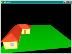
6. Roof
The next element that was added to the program was the roof. Before a roof element was inserted, the program would go through the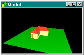 link list and make sure that a room was located right underneath the current
location of the roof. If the program found a room under its current
location, a dialog would pop up and asked the user to pick one of the 12
types of roof. When creating the roofs in the model view, the normal
for the top of the roof are all different, therefore each normal has to
be calculated. This was done by finding the diagonal of the roof,
and used this value to normalize the 2 components (x or z, and y) in the
normal vector so that it will always have a magnitude of 1 (see below).
This would provide correct lighting and shading for the roofs.
link list and make sure that a room was located right underneath the current
location of the roof. If the program found a room under its current
location, a dialog would pop up and asked the user to pick one of the 12
types of roof. When creating the roofs in the model view, the normal
for the top of the roof are all different, therefore each normal has to
be calculated. This was done by finding the diagonal of the roof,
and used this value to normalize the 2 components (x or z, and y) in the
normal vector so that it will always have a magnitude of 1 (see below).
This would provide correct lighting and shading for the roofs.
normalizex = sqrt(height*height + (0.5*abs(right-left))*(0.5*abs(right-left)) );
glNormal3d(0.0 , height/normalizex, -0.5*abs(right-left) / normalizex);
7. Delete
At this point, only the last element inserted into the design could be deleted. A delete function was implemented so that whenever the user selects an element with the cursor, the element can be deleted. All elements can be deleted by selecting them and hit the delete button except for the room, which the user has to make sure that there are no other elements, such as doors, windows, or roofs, associated to it. A search on the link list will be performed to ensure that the room is not connected to any of these components.8. Viewing Mode
Another model viewing mode was added after the implementation of delete, and that is virtual walk-through. The camera can now be moved around
in 3D space, with the up-vector always pointing up. When the walk-through
mode is enabled, user can move forward, backward, turn right, left, up
and down. The restriction is that the user can only move towards
the direction that he/she is looking at. At this point, there is
no restriction on where the camera could be. It can therefore travel
through walls and windows, and clipping might occur. Also, the current
viewing angle is set to 30, so a slight fisheye effect exists.
around
in 3D space, with the up-vector always pointing up. When the walk-through
mode is enabled, user can move forward, backward, turn right, left, up
and down. The restriction is that the user can only move towards
the direction that he/she is looking at. At this point, there is
no restriction on where the camera could be. It can therefore travel
through walls and windows, and clipping might occur. Also, the current
viewing angle is set to 30, so a slight fisheye effect exists.
9. Optimization
After I was done with the walk-through mode, I started optimizing the code. A lot of floating point calculations were reduced after optimization, and I used the command glHint to optimized the speed of rendering. The difference was quite obvious, especially when the window size is large.10. Help files
Help files were the last part that I worked on. I experienced problem compiling the help file initially because the help compiler is 16-bit and it has problem reading the afxcore.rtf file. This problem can be fixed by obtaining a 32 bit compiler or converting the rtf file into 16-bit format. These programs are available online and could be found on www.shareware.com.Result:
1. Instructions
The program has been tested and all functions seem to work properly. Here are some basic instructions for designing a model:-
To select an existing element on the design view, click on the
 button on the toolbar. Click on any element within the design view
with the left mouse button.
button on the toolbar. Click on any element within the design view
with the left mouse button. -
To create a room, click on the
 button on the toolbar. With the left mouse button down, drag on the
grid and release the button when the desired size is achieved.
button on the toolbar. With the left mouse button down, drag on the
grid and release the button when the desired size is achieved. -
To create a door, click on the
 button on the toolbar. A dotted box would appear when left mouse
button is held down. Drag the box to a place where it intersects
with one side of a room; then release the mouse button.
button on the toolbar. A dotted box would appear when left mouse
button is held down. Drag the box to a place where it intersects
with one side of a room; then release the mouse button. -
To create a window, click on the
 button on the toolbar. Follow the same steps as in creating a door.
 -
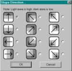
To create a roof, click on the
 button on the toolbar. Follow the same instructions as in creating
a room, except that the final rectangle must intersect with a room.
A slope dialog would pop up. Select 1 of the 12 different slope directions:
Selection from the first column gives you roofs of type I; selection from
the second column gives you roofs of type II; and selection from the third
column gives you type III roofs.
button on the toolbar. Follow the same instructions as in creating
a room, except that the final rectangle must intersect with a room.
A slope dialog would pop up. Select 1 of the 12 different slope directions:
Selection from the first column gives you roofs of type I; selection from
the second column gives you roofs of type II; and selection from the third
column gives you type III roofs. -
To enable transparency, click on the
 button on the toolbar.
 -
To change to normal mode in the model view, click on the
 button on the toolbar.
 -
To change to walk-through mode in the model view, click on the
 button on the toolbar.
 - To rotate the model in normal mode, hold down the left mouse button and move around.
- To move around the model in the walk-through mode, use 5 for forward, 0 for backward, 4 for left, 6 for right, 8 for up and 2 for down.
 |
 |
 |
 |
Slope Dialog |
Type I, For side |
Type II, For corner |
Type III, For corner |
2. Performance
Testing were done on a Dell 300MHz Pentium II with 8Mb video RAM. With a mid-size model, rotation on the model was very smooth with the viewing area approximately equal to 576 x 432. The frame rate decreased to approximately 4-5 frames/second when the transparency was turned on. With the viewing area approximately equal to 288 x 216, turning on the transparency decreased the frame rate by a little, but it was still above 10 frames/sec. With the whole base filled up with rooms, the frame rate decreased to approximately 7-8 frames/second, with the size of the viewing area equal to 576 x 432. When transparency was on, the frame rate drops to 1frame/second with the same viewing size.3. Bugs and Problems
The program didn't turn out to have a lot of big problems, though minor problems exist. One problem with the design view was that when the user needs to draw a room that has a larger size than the viewable area, the screen will not scroll down automatically.Another problem with the design view was that random dots appear on the screen once in a while during dragging operations. This rarely happens, but it is a little annoying to users. I was examining my code and tried to find out what I did wrong, but I did not find any major problem with my code. I then tried to drag rectangles on the desktop and in other windows, and I noticed that the same problem occurs. My conclusion for this problem was that this might be a bug in windows.
The main problem for the model view is clipping when
the user is in the walk-through mode. Some algorithms could be applied
to eliminate this problem, but I haven't come up with a good solution at
this point.
Texture mapping was originally added to the program.
Users were allowed to define a wallpaper for the rooms. The fucntion
was taken off after transparent function was added due to the effect on
rendering speed. When both texture mapping and transparency was on,
the rendering speed was extremely slow. Since this is a design program,
the ability to see all the rooms seems to have a higher priority then the
ability of making nice looking rooms, therefore texture mapping option
was taken off.