Physiological Stimulus Isolator
Introduction
The goal of this project was to build a small, cheap, light-weight
stimulus-isolator unit (SIU) for student use in electrophysiology labs.
Specifically:
- Isolation should be good (resistance>1Gohm, capacitance<20pf).
- Voltage range at the output should be 0-100 volts, supplying about one
watt of power (10 mA at 100 volts).
- The SIU should not use batteries. Power must be supplied across the
galvanic isolation.
- The SIU should be cheap, less than $100 to build, perferably less
than $50.
- Analog control of the output voltage is very desirable, but
pulse-output only would be acceptable.
The hardest
goal to meet was not having batteries on the isolated output side. We tried
photovoltaic optoisolators, but they could not supply enough power for the
cells we were interested in stimulating. However, the photovoltaic isolators
would work great for driving microelectrodes. More to follow on that topic
at a later time.
We decided to try DC-to-DC converters
which were fast, had low coupling capacitance, and produced over 30 volts at
the output, isolated from a 6 volt supply. They are meant to be used to
provide power to small circuits, but the isolation seemed good enough to
use for an SIU.
The Circuit
The SIU is built around the
Burr-Brown
DCP010515D DC-to-DC converter purchased from
Digikey.
To get 100 volts we used three of them. If you only need 30 volts, use
just one.
The devices are rated to run at
5 volts input, but we ran them at 6 volts to produce more output voltage.
Stepping through the Circuit:
- The transistor at the input (along with the two diodes) limits,
amplifies, and inverts the input pulse. The output of the transistor is
a logic-level pulse suitable for driving the CMOS quad transmission gate.
- The CMOS transmission gate acts to ground the "synch in" pins of all three
DC-to-DC converters. Grounding the synch pins turns them off. A high voltage
at the input results in a low voltage at the output of the transistor, which
turns off the transmission gate and turns on the converters. It is imperative
that the wire from the transmission gate to the converters be as short as
possible and minimize capacitance to ground. To much ground capacitance on
this pin will slow down the internal oscillator and noise and poor response
on the output. The output is thus on or off depending on a pulse at the input.
Output amplitude is controlled by the potentiometer. Be sure to ground all
inputs to the 4066 which are not used. CMOS gates tend to draw lots of current
if their inputs are left unconnected.
- The three converters are connected in series to produce 90-100 volts.
Note: The series output will hurt if you short
your hand across it. Use caution with all high voltage sources.
The 1 nF capacitors should be connected close to each converter. The
converters are noisy if the capacitors are too far away. the 5 nF capacitor
and 10 kohm potentiometer form a low-pass filter to absorb some of the
400 kHz noise produced by the converters.
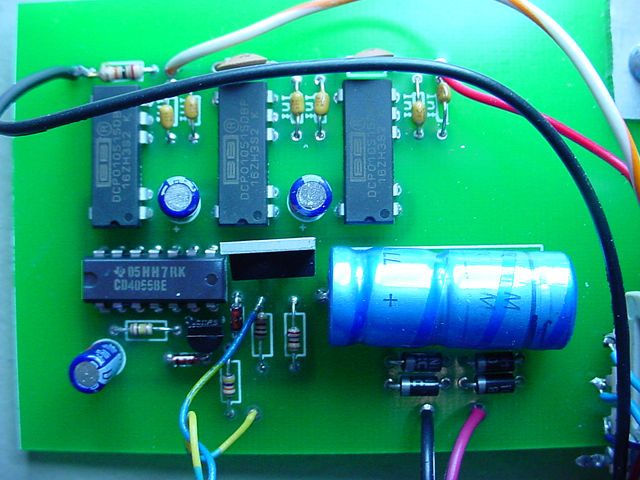
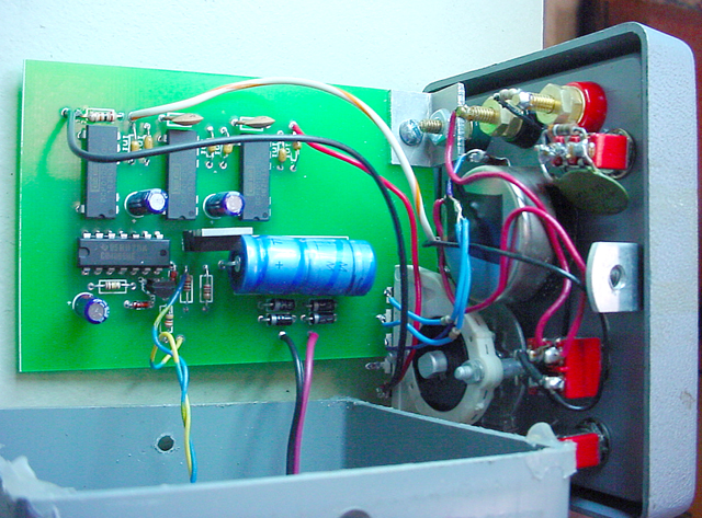
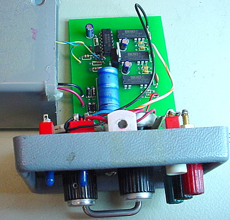
Physical layout of the circuit
The circuit was placed in a plastic box to reduce capcitative coupling to
ground. The transistor and 4066 should be placed away from the outputs of the
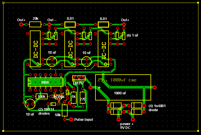
converters for the same reason. A printed circuit board was produced to ease
constuction and cut down on stray capacitance. The expressPCB.com design
file requires free, downloadable software
to view, order, or modify. The board layout is shown below. Out+
and Out- go to the two ends of the output level potentiometer shown
in the schematic.
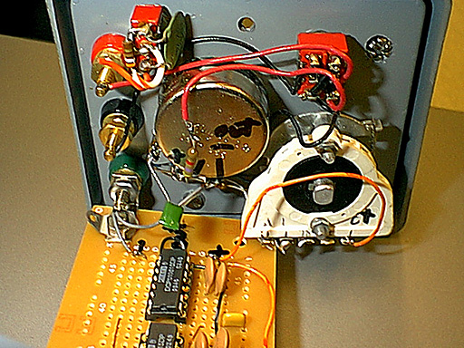
The circuit was built into a discarded WPI stimulus isolator chassis. all front
panel controls were from the original WPI design.
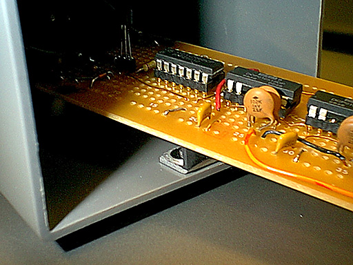
More photos
The first three pictures are the original, hand wired model.

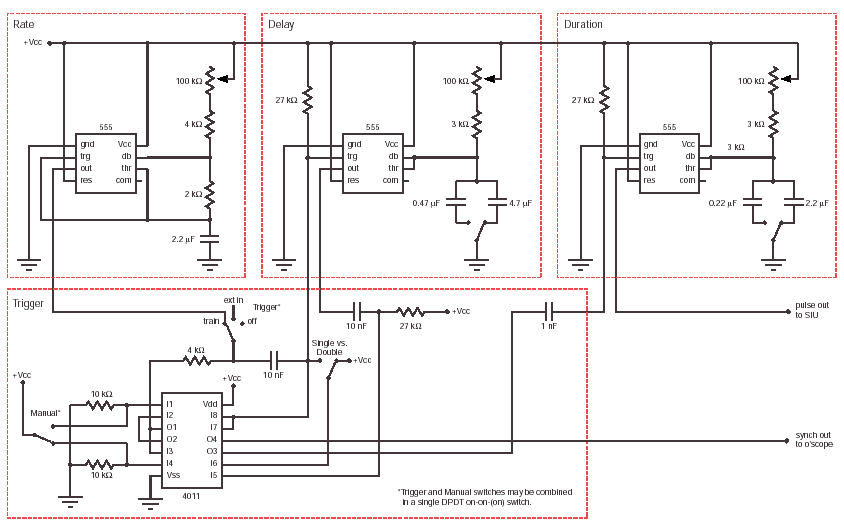
Analog stimulator
A circuit was designed to control the isolator. The circuit is very similar
in overall function to the classic Grass stimulator. It produces one or two
pulses with controllable frequency, pulse spacing/pulse delay, and pulse duration.
It can be manually or remotely triggered. It produces a trigger output. A schematic
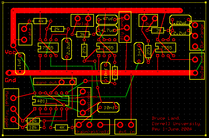
and circuit board are shown. The board was designed with expresspcb
software and can be viewed, modified and ordered using the free software. Note
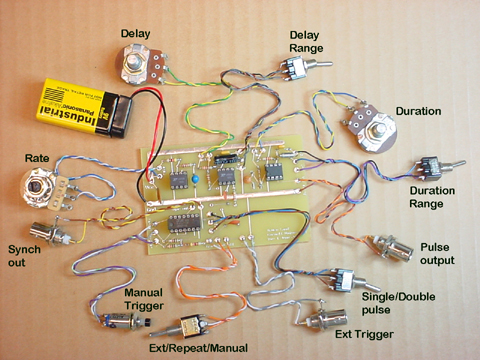
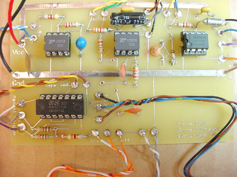
that the controls must be attached to the board as shown in the photographs
below.